
Related Manuals for SKF DU1-GKS EEX


Summary of Contents for SKF DU1-GKS EEX
- Page 1 Operating Instructions Pressure-controlled change-over device following ATEX directive 2014/34/EU DU1-GKS EEX 951-181-015-EN Version 03 2020/11/16...
-
Page 2: Eu Declaration Of Conformity Following Atex Directive 2014/34/Eu
EU Declaration of conformity following ATEX directive 2014/34/EU, annex X The manufacturer, SKF Lubrication Systems Germany GmbH, Walldorf Facilities, Heinrich-Hertz-Str. 2-8, DE - 69190 Walldorf hereby declares under sole re- sponsibility that the electrical equipment Designation: Pressure-controlled change-over device Types:... -
Page 3: Legal Notice
SKF Lubrication Systems Germany GmbH In order to provide a maximum of safety and The manufacturer shall not be held respon- e-mail: Lubrication-germany@skf.com economic viability, SKF carries out detailed sible for damages caused by: skf.com/lubrication ○ non appropriate use training courses. It is recommended that the training courses are attended. -
Page 4: Table Of Contents
Table of contents Table of contents EU Declaration of conformity following ATEX directive 2014/34/EU ..2 Legal notice ....................3 Explanation of symbols, signs and abbreviations ........6 1.21 Explosion protection marking ..............16 Safety instructions .................8 1.22 Residual risks ..................17 General safety instructions ..............8 1.23 Residual risks ATEX ................18 General behaviour when handling the product ........ - Page 5 Table of contents Installation .................. 29 Maintenance ................38 General information ................29 Troubleshooting ................39 Place of installation ................29 Minimum assembly dimensions ............30 Repairs ..................40 6.3.1 Installation bores ..................31 12.1 Specialist for maintenance and repairs in potentially Lubrication line connection ..............32 explosive atmospheres .................40 Adjusting the change-over pressure ..........33 6.5.1...
-
Page 6: Explanation Of Symbols, Signs And Abbreviations
Explanation of symbols, signs and abbreviations Explanation of symbols, signs and abbreviations The following abbreviations may be used within these instructions. Symbols within safety notes mark the kind and source of the hazard. General warning Dangerous electrical voltage Risk of falling Hot surfaces Unintentional intake Crushing hazard... - Page 7 Explanation of symbols, signs and abbreviations Abbreviations and conversion factors regarding °C degrees Celsius °F degrees Fahrenheit approx. approximately Kelvin Ounce i.e. that is Newton fl. oz. fluid ounce etc. et cetera hour inch poss. possibly second pounds per square inch if appl.
-
Page 8: Safety Instructions
1. Safety instructions 1. Safety instructions 1.2 General behaviour when handling the 1.1 General safety instructions ○ Safety-related protective and emergency product ○ The owner must ensure that safety infor- devices must not be removed, modified ○ The product may be used only in aware- or affected otherwise in their function mation has been read by any persons en- ness of the potential dangers, in proper... -
Page 9: Intended Use
1. Safety instructions 1.3 Intended use ○ in areas with aggressive or corrosive ma- ○ in explosive dust atmospheres, the mini- Changing over of the main lines within a terials (e.g. high ozone pollution). These centralized lubrication system following mum ignition and glow temperature of may affect seals and painting. -
Page 10: Modifications Of The Product
1. Safety instructions 1.6 Modifications of the product 1.8 Inspections prior to delivery Where appropriate: Unauthorized conversions or modifica- The following inspections were carried out ○ Project planning documents tions may result in unforeseeable impacts prior to delivery: ○ Safety and functional tests on safety. -
Page 11: Notes Related To The Type Identification Plate
Pressure Equipment Directive 2014/68/EU P. No. ________________________________ following Article 1 (2) (f). S. No. ________________________________ Year of construction ____________________________ SKF Lubrication Systems Germany GmbH Model: xxx -xxx-xxx-xxx-xxx P. No.: xxxxxxxxxxxxxxxx S. No.: xxxxxxxxxxxxxxxx -xx °C ≤... -
Page 12: Persons Authorized To Operate The Pump
1. Safety instructions 1.12 Persons authorized to operate the 1.13 Briefing of external technicians pump Prior to commencing the activities, external technicians must be informed by the opera- 1.12.1 Operator 1.12.4 Specialist for maintenance and tor of the company safety provisions, the repairs in potentially explosive A person who is qualified by training, know- applicable accident prevention regulations... -
Page 13: Transport, Installation, Maintenance, Malfunctions, Repair, Shutdown, Disposal
1. Safety instructions ○ Ensure proper connection of the protec- ○ Assemble the product only outside of the 1.15 Transport, installation, maintenance, operating range of moving parts, at an tive conductor. malfunctions, repair, shutdown, disposal adequate distance from sources of heat ○... -
Page 14: Cleaning
1. Safety instructions ○ No parts of the centralized lubrication 1.16 Initial commissioning, daily start-up 1.17 Cleaning system may be subjected to torsion, ○ Risk of fire and explosion when using Ensure that: shear, or bending. ○ All safety devices are completely available inflammable cleaning agents Only use ○... -
Page 15: Special Safety Instructions Regarding Explosion Protection
1. Safety instructions 1.18 Special safety instructions regarding explosion protection ○ The ignition temperature of the ambient ○ Repairs or modifications to machines ○ Always behave so that explosion hazards which are protected against explosions explosive gas and vapour atmospheres are avoided. -
Page 16: Expiry Of The Atex Approval
○ Unauthorized modifications signal leads to a new hazard potential according to directive 1999/92/EC ○ Use of non-original SKF spare parts (e.g. through heat-up of bearing points (ATEX 137). on the machine in the area of ignition ○... -
Page 17: Residual Risks
1. Safety instructions 1.22 Residual risks Residual risk Possible in life cycle Prevention/ remedy Personal injury/ material damage due to Keep unauthorized persons away. No people may remain under suspended A B C G H K falling of raised parts loads. -
Page 18: Residual Risks Atex
1. Safety instructions 1.23 Residual risks ATEX Residual risk Possible in life cycle Prevention/ remedy Usage in a potentially explosive atmos- Check the equipotential bonding with regard to electrical continuity before the phere without testing the equipoten- initial start-up, after each repair and additionally at regular intervals to be deter- tial bonding with regard to electrical mined by the operator. - Page 19 1. Safety instructions Residual risk Possible in life cycle Prevention/ remedy Generation of electrostatic charges and sparks Secure parts against falling. Where appropriate, cover parts in order to C D E F G through dropping parts. avoid the formation of sparks. Bringing catalytic, unstable or pyrophoric sub- Ensure that none of these substances gets into the potentially explosive C D E F G...
-
Page 20: Lubricants
2.3 Material compatibility 2.2 Selection of lubricants Lubricants are used specifically for certain SKF considers lubricants to be an element Lubricants must generally be compatible application purposes. In order to fulfil their of system design. A suitable lubricant is se- with the following materials: ○... -
Page 21: Ageing Of Lubricants
(e.g. "bleeding"). on the packaging have to be Please contact SKF. if you have further observed. questions regarding lubricants. You may request an overview of the lubri- cants tested by SKF. -
Page 22: Overview, Functional Description
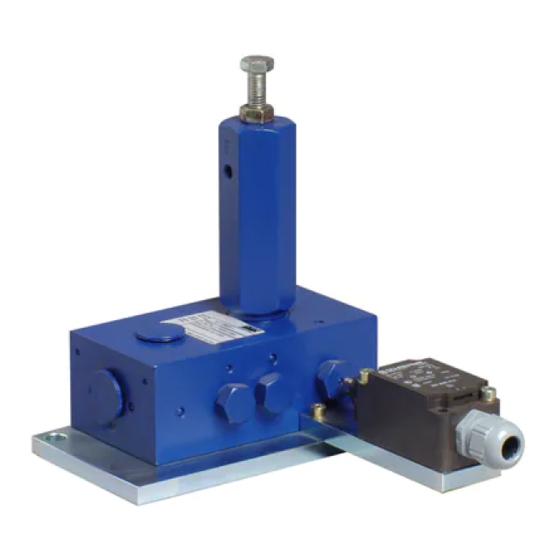
3. Overview, functional description 3. Overview, functional description Overview Fig. 1 Functional principle: From its functioning principle, the pressure- controlled change-over device DU1 EEX corre- sponds to a pressure-controlled 4/2-way valve, i.e. all piston movements in the change-over device DU1 EEX are effected exclusively by dif- ferent pressure conditions on the pistons. - Page 23 4. Technical data Overview Fig. 2 2 Set the change-over pressure The change-over pressure can be increased or reduced by unscrewing the counternut (2.1) and turning the adjusting screw (2.2). The spring housing accommodates a vent bore (3) for pressure compensation. 4 Position switch Depending on its mounting position to the change-over device, the position switch (4) is...
- Page 24 4. Technical data Overview Fig. 3 5 Base plate The base plate (5) accommodates all parts of the change-over device. The change-over device is connected to the equipotential bond- ing of the superior machine via the base plate. To do so a large-area metallic contact of the base plate and the superior machine must be ensured.
-
Page 25: Technical Data
4. Technical data 4. Technical data 4.1 Technical data of the DU1 EEX Explosion protection marking II2G Ex h IIC T6 Gb II 2D Ex h IIIC T80°C Db Equipotential bonding The equipotential bonding is carried out by a large-area metallic contact via the base plate Ambient temperature range min. -
Page 26: Position Switch
4. Technical data 4.2 Position switch Part number 2360-00000260 Identifier 8074/ 2 II 2G Ex de IIC T6/T5 Gb Type-examination certificate BVS 05 ATEX E 007 Explosion protection marking II 2D Ex tb IIC T80 °C..T95 °C Db Service life switching cycles Electrical data Mechanical data... -
Page 27: Tightening Torques
4. Technical data 4.3 Tightening torques The stated tightening torques must be adhered to. DU1 EEX with base/ superior machine 30 Nm ± 0,1 Nm Position switch to bracket of DU1 EEX 1.2 Nm ± 0,1 Nm Lid screws to position switch 0.7 Nm max. -
Page 28: Delivery, Returns, And Storage
(ageing). 5.2 Returns Clean all parts and pack them properly (i.e. SKF products are subject to the following following the regulations of the recipient storage conditions: country) before returning them. ○ the admissible storage temperature... -
Page 29: Installation
6. Installation 6. Installation 6.2 Place of installation 6.1 General information ○ Observe prescriptions in the Technical Protect the product against humidity, dust Only qualified technical personnel may data (chapter 4) regarding the installation and vibrations and install it in an easily ac- install the products described in these position. -
Page 30: Minimum Assembly Dimensions
6. Installation 6.3 Minimum assembly dimensions Minimum assembly dimensions DU1 EEX Fig. 4 Ensure sufficient space for maintenance or repair work or for assembly of further components of the centralized lubrication system by leaving a free space of at least 100 mm into each direction in addition to the stated dimensions. -
Page 31: Installation Bores
6. Installation 6.3.1 Installation bores Installation bores Fig. 5 NOTICE Damaging of the product Fastening may not be done on two parts moving against one another (machine bed and machine assembly). The product is fastened on the 2 mounting bores (6). Drill the mounting bores on non load-bearing parts only. -
Page 32: Lubrication Line Connection
6. Installation 6.4 Lubrication line connection ○ The lubricant flow should not be impeded Observe the following installation instruc- CAUTION by the installation of sharp elbows, angle tions for safe and smooth operation. ○ Use clean components and primed lubri- valves, gaskets protruding to the inside, Risk of falling or cross-section changes (big to small). -
Page 33: Adjusting The Change-Over Pressure
6. Installation Adjusting the change-over pressure Fig. 6 6.5 Adjusting the change-over pressure 6.5.2 Reduce the change-over pressure 6.5.1 Increase the change-over pressure The change-over pressure must always exceed the The change-over pres- required actuation pressure sure must not exceed the of the dual-line metering max. -
Page 34: Electrical Connection Of The Position Switch
6. Installation 6.6 Electrical connection of the position Electrical connection of the position switch Fig. 7 switch The electrical connection of the position switch (3) follows the connection diagram in chapter Technical data of the position switch. WARNING Risk of explosion When carrying out electrical instal- lation works on explosion-protect- ed machines, observe the legal and... -
Page 35: Initial Start-Up
7. Initial start-up 7. Initial start-up In order to warrant safety and function, a person assigned by the operator must carry out the following inspections. Remedy detected de- fects before the initial start-up. Deficiencies may be remedied by an authorized and qualified specialist only. Checklist - Inspections prior to the initial start-up 7.1 Inspections prior to initial start-up Electrics... -
Page 36: Operation
8. Operation 8. Operation SKF products operate automatically to the greatest possible extent. Basically, activities during standard opera- tion are limited to the control for damages and the outside cleaning of the product in case of contamination. 8.1 Activating the DU1 EEX The DU1 EEX is activated by: ○... -
Page 37: Cleaning
To do so, contact the Thoroughly remove residues • Mark and secure wet areas. SKF Customer Service. of cleaning agents from the • Keep unauthorized persons away. product and rinse off with clear water. -
Page 38: Maintenance
10. Maintenance Maintenance Regular and appropriate maintenance is WARNING a prerequisite to detect and clear faults in time. As it is not possible for us to exactly Risk of explosion define the operating conditions, we cannot When carrying out installation or indicate any definite deadlines. -
Page 39: Troubleshooting
11. Troubleshooting Troubleshooting In case of any malfunction, first of all, check whether the pump achieves the full pressure. 11.1 Fault table of the DU1 EEX Fault Possible cause Remedy Change-over device does not change Worn change-over piston over, Notice: Lubricant is supplied to the Replace change-over device no pressurization of the system pump via the return line connection... -
Page 40: Repairs
12. Repairs Repairs 12.1 Specialist for maintenance and The work described should WARNING repairs in potentially explosive possibly be done at room tem- atmospheres Risk of injury perature in a workshop. At low Before carrying out any repair temperatures the work may be A person who is qualified by training, know- work, take at least the following subject to restrictions. -
Page 41: Shutdown And Disposal
13. Shutdown and disposal Shutdown and disposal 13.1 Temporary shutdown 13.3 Disposal Temporarily shut the system down by: Countries within the European Union ○ Switching off the superior machine Disposal should be avoided or minimized ○ Disconnecting the product from the Dispose of or recycle electrical wherever possible. -
Page 42: Spare Parts
14. Spare parts Spare parts The spare parts assemblies may be used exclusively for replacement of identical defective parts. Modifications with spare parts on existing products are not allowed. Fig. 8 14.1 Position switch Designation Qty. Part number Position switch 2360-00000260 951-181-015 - 42 -... -
Page 43: Declaration Of Conformity Of The Position Switch
Annex Declaration of conformity of the position switch 951-181-015 - 43 - Version 03... - Page 44 SKF Lubrication Systems Germany GmbH Walldorf Facilities Heinrich-Hertz-Str. 2-8 DE - 69190 Walldorf Phone +49 (0) 6227 33-0 Fax: +49 (0) 6227 33-259 e-mail: Lubrication-germany@skf.com www.skf.com/lubrication 951-181-015-EN Version 03 2020/11/16...
Need help?
Do you have a question about the DU1-GKS EEX and is the answer not in the manual?
Questions and answers