Table of Contents
Advertisement
Quick Links
SKF Multilog On-Line
System IMx-M
User Manual Part No. 32179800-EN
Revision O
Protection FW 364
IMx-M Manager 2.1.22
WARNING! Read this manual before using this product. Failure to follow the
instructions and safety precautions in this manual can result in serious injury, damage
to the product, or incorrect readings. Keep this manual in a safe location for future
reference.
Copyright 2016 by SKF Group
All rights reserved.
SKF Condition Monitoring Center – Luleå
Aurorum 30, 977 75 Luleå, Sweden
Telephone: +46 (0) 31 337 10 00, Fax: +46 (0) 920 134 40
User manual
Advertisement
Table of Contents

Related Manuals for SKF IMx-M


Summary of Contents for SKF IMx-M
- Page 1 Keep this manual in a safe location for future reference. Copyright 2016 by SKF Group All rights reserved. SKF Condition Monitoring Center – Luleå...
- Page 2 SKF reserves the right to alter any part of this publication without prior notice.
-
Page 3: Table Of Contents
Table of Contents Introduction Important Messages ..........1-1 System Overview ............1-5 IMx-M General Overview .......... 1-6 Protection Safety Considerations ..........2-1 Accuracy ............... 2-2 Measurement Types ..........2-3 Alarms ................ 2-20 Relays ................. 2-25 Protection Part Operation ........2-32 IMx-M Manager ............ - Page 4 Digital Measurement - CM ........7-5 Signal Processing - CM ..........7-5 Interface - CM ............. 7-5 Miscellaneous.............. 7-5 Quality Control ............7-6 Drawings and Connections ........7-7 Electrical Waste Glossary Limited Warranty Index TOC - 2 SKF Multilog On-Line System IMx-M User Manual...
-
Page 5: Introduction
Important messages, instructions and information in this manual must be followed carefully. Otherwise, harm might occur to equipment and/or personnel. IMx-M shall be used for speed alarming only. It shall not be used to protect/trip machine on overspeed. IMx-M does not fulfill the requirements related to overspeed protection. - Page 6 Be sure to read "Signal Grounding" and "Signal Isolation" chapters thoroughly and understand them. • SKF USB isolator cables must always be used when connecting to IMx-M USB ports. • Equipment connected to buffered outputs must be isolated from the protective earth.
- Page 7 Caution to a possible hazard due to mains power double pole/neutral fusing. An IMx-M rack must be situated in a cabinet with a metal bottom or plastic bottom with flammability classification of at least V-1. The cabinet must fulfill at least IP 20.
- Page 8 DIP switch settings must be handled with a special care to prevent any damage to the IMx-M rack: • Do NOT change DIP switch settings while the IMx-M rack is powered-up, as this may cause damage and void warranty. •...
-
Page 9: System Overview
Introduction System Overview System Overview The SKF Multilog On-line System IMx-M is the latest addition to the current generation of powerful, cost effective solutions suitable for a variety of machinery monitoring applications. Together with SKF @ptitude Monitoring Suite software, the SKF Multilog IMx-M can provide a complete system for initiation of machinery shutdown, early fault detection and diagnosis. -
Page 10: Imx-M General Overview
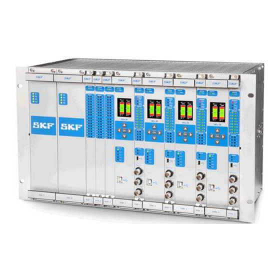
Figure 1 - 2. A Fully Equipped IMx-M Rack. The above figure shows an example of a fully equipped IMx-M rack with (from left to right) two redundant power supply units, three relay modules and four pairs of a condition monitoring module and a protection module. -
Page 11: Protection
• The rack is offering remote reset of latching alert/danger conditions. • All channels are fully computed in parallel, both condition monitoring and machine protection. SKF Multilog On-Line System IMx-M 1 - 7 User Manual... - Page 12 IMx-M memory. • The configuration is retained in the event of power losses, so that the IMx-M can start automatically when power returns. SKF Multilog On-Line System IMx-M...
- Page 13 IMx-M General Overview IMx-M Mean Time to Failure (MTTF) IMx-M MTTF was calculated to 20,8 years, where the protection module has 25,2 years, the relay module has 139,6 years and the backplane has 772,3 years. The calculation was done under the environmental conditions 40 °C / 104 °F and for the following configuration of the IMx-M machinery protection system: •...
-
Page 15: Safety Considerations
Hot-swap of any module in the Protection functionality of Rack is not active because the rack (all slots) shall be rack in disarm mode during a properly performed hot-swap procedure. SKF Multilog On-Line System IMx-M 2 - 1 User Manual... -
Page 16: Accuracy
The following diagram shows an example of same or different readings for PRM and CMM depending on the input signal frequency in conjunction with filters. Figure 2 - 1. Comparison of PRM and CMM Readings. SKF Multilog On-Line System IMx-M 2 - 2 User Manual... -
Page 17: Measurement Types
• Position • Radial Shaft Vibration • Temperature Combined Measurements • Absolute Shaft Vibration • Complementary Differential Expansion • Piston Rod Drop XY • Temperature Difference Digital Channels • Speed SKF Multilog On-Line System IMx-M 2 - 3 User Manual... - Page 18 Measuring the Vibration of the Machine. • Displacement of the shaft relative to the machine itself (um #2), which can be determined by means of a proximity probe, secured firmly to the machine casing. SKF Multilog On-Line System IMx-M 2 - 4 User Manual...
- Page 19 Determining the Absolute Shaft Vibration. Casing Vibration Casing vibration is used for measuring vibration on machines such as gears, pumps, fans, and motors equipped with rolling element bearings (API670 definition). SKF Multilog On-Line System IMx-M 2 - 5 User Manual...
- Page 20 Sensor S1 is selected as the master sensor. It is the output of this sensor which will determine when measuring of the displacement will switch from Sensor S1 to Sensor S2. SKF Multilog On-Line System IMx-M 2 - 6 User Manual...
- Page 21 The Gap alarming can be used in conjunction with Radial shaft vibration or Eccentricity as a means of protecting the shaft from touching the proximity probe by setting an alarm if the shaft gets outside the configured alarm levels. SKF Multilog On-Line System IMx-M 2 - 7 User Manual...
- Page 22 It is possible to configure a measurement in such a way that the utilized input voltage range is so small that the measurement will suffer loss of resolution. SKF Multilog On-Line System IMx-M 2 - 8 User Manual...
- Page 23 Important - Standard 0-10 V or 4-20 mA process control signaling does not mean that IMx-M can read any possible DC voltage or current in this range. If other voltage ranges or current ranges are utilized there may be loss of accuracy and resolution.
- Page 24 They specify the part of the revolution at which the measurement will be based. Start and stop angles close to the end of the revolution should be avoided. See "Measurement Angle" and "Measurement Angles and Non Constant Speed" in Triggered Mode. SKF Multilog On-Line System IMx-M 2 - 10 User Manual...
- Page 25 The alarm setting must be configured for each digital input in use, including the inputs connected to buffered outputs. See Alarm Levels for Speed Type in Digital Channels in IMx-M Manager. SKF Multilog On-Line System IMx-M 2 - 11...
- Page 26 There is always a minimum of 1 sample in a measurement. Figure 2 - 9. Visualization of Start and Stop Angles. Red shading indicates unsafe angles close to trigger point. (360°). SKF Multilog On-Line System IMx-M 2 - 12 User Manual...
- Page 27 The reference point (0°) is the point where the speed sensor will deliver a falling edge to the digital input. SKF Multilog On-Line System IMx-M 2 - 13 User Manual...
- Page 28 If the associated digital channel is NOT configured for the Speed measurement The measurement is the average of the samples collected during a fixed time (0.8 seconds). At the completion of one measurement the next one will immediately be initiated. SKF Multilog On-Line System IMx-M 2 - 14 User Manual...
- Page 29 Trigger System and Measuring Angles In order for the measurement system to operate correctly, in both Average mode and Triggered mode, it is required that the digital channel is configured for measuring speed. SKF Multilog On-Line System IMx-M 2 - 15 User Manual...
- Page 30 When there is a need for triggering several Piston rod drop measurements, distributed over several analog channel pairs, from one single phase reference transducer / tacho sensor the following approach shall be deployed. SKF Multilog On-Line System IMx-M 2 - 16 User Manual...
- Page 31 The digital channel buffered outputs (Buf SKF Multilog On-Line System IMx-M 2 - 17 User Manual...
- Page 32 However, it is also used as an input parameter for piston rod drop measurements and the edge of the input pulse is used as trigger. SKF Multilog On-Line System IMx-M 2 - 18 User Manual...
- Page 33 Temperature is measured with RTD (PT100) sensors. The measurement range is −20 − to +150 °C ( 4 to +302 °F) Temperature difference measures the temperature difference between two Temperature measurement type channels. SKF Multilog On-Line System IMx-M 2 - 19 User Manual...
-
Page 34: Alarms
Protection Alarms Alarms The IMx-M Protection Module supports a number of different types of alarms • Alert: A configured parameter value at which an Alert alarm is activated in order to warn of a condition that requires corrective action. •... - Page 35 PRM: The alarm status information update process 1. Measurement performed 2. Measurement value evaluated against configured alarm levels and hysteresis 3. Alarm status information updated and made available 4. LED indicators in front panel updated SKF Multilog On-Line System IMx-M 2 - 21 User Manual...
- Page 36 The hysteresis value is used to determine an adjusted value at which to leave the alert/danger state. The hysteresis value would normally be large enough to encompass the anticipated fluctuations/noise. SKF Multilog On-Line System IMx-M 2 - 22 User Manual...
- Page 37 (alarm level adjusted with configured hysteresis) before the alarm condition is canceled. Alert/Danger "OFF" trigger will be delayed by this Leave Time. SKF Multilog On-Line System IMx-M 2 - 23 User Manual...
- Page 38 When a channel or a slot is armed, the information of the first out indication is – valid if only one channel is in danger at the time of arming. SKF Multilog On-Line System IMx-M 2 - 24 User Manual...
-
Page 39: Relays
Relays Each IMx-M rack can be fitted with a maximum of three relay modules. Each relay module contains 32 separate relays, consisting of 28 single pole, double throw (SPDT) and four double pole, double throw (DPDT) relays. This means that each IMx-M rack can have up to a maximum of 96 relays available for configuration and use. - Page 40 Relay Module (RLM) within LED Indicators. • For the physical layout of relay connectors, refer to Relay Module (RLM) Connections. The following table shows the different relay types and their behaviors. SKF Multilog On-Line System IMx-M 2 - 26 User Manual...
- Page 41 Triggered Triggered Triggered Not triggered Previous status Not triggered Analog Ch Danger Not triggered Triggered Not triggered Previous status Analog Ch Danger or Ch Not triggered Not OK* Triggered Triggered SKF Multilog On-Line System IMx-M 2 - 27 User Manual...
- Page 42 When configuring a redundant relay setup, select relays of different processors. For example, use relay 1 and relay 5 to ensure that one circuit fault does not effect both relays. See the table below for details of relay assignments. SKF Multilog On-Line System IMx-M 2 - 28 User Manual...
- Page 43 Important - It is important to configure relays correctly to ensure that one circuit fault effects no more than two channels. Each relay module is consisted of eight individual processors, and each processor controls four relays. SKF Multilog On-Line System IMx-M 2 - 29 User Manual...
- Page 44 Status Not triggered Disarm Triggered Not triggered Triggered Not triggered Circuit Fault Triggered Not triggered - = Not applicable ** Refer to the table Behavior of Relay at Channel Startup SKF Multilog On-Line System IMx-M 2 - 30 User Manual...
- Page 45 Not triggered due to Triggered Triggered Relay module relay module removal relay module removal hot swap (slot disarm assumed) *During reset or power down, all relays will be in non-energized state. SKF Multilog On-Line System IMx-M 2 - 31 User Manual...
-
Page 46: Protection Part Operation
1. Configure hardware DIP switch settings Connect cables (sensors, relay outputs, circuit fault relay, disarm, 4- 20 mA, RS485, Ethernet, etc.). Verify sensors and connections. 2. Create system configuration in IMx-M Manager • System power on 1. Disarm system 2. Connect power 3. - Page 47 You might see entries in the Event log of danger/alert reported on measurements with cable faults. This is logged only for internal event tracing purposes. SKF Multilog On-Line System IMx-M 2 - 33 User Manual...
- Page 48 PSU 2 voltage failure: 0x0200 User configuration dependent. Check IMx-M configuration settings. Check that PSU 2 is firmly positioned. CF_CALIB2 Calibration table error: 0x0400 Check that modules are firmly positioned. SKF Multilog On-Line System IMx-M 2 - 34 User Manual...
- Page 49 Normal. No errors. (0x0000) (No bit set) CF_CONFIG User configuration dependent. 0x0001 Check IMx-M configuration settings. Check the PRM position. CF_RS485INT Internal RS485 communication error - check that modules 0x0002 are firmly positioned. Master and slave may have different firmware versions in use - check the current firmware version in use (intd0) on both master and slave.
- Page 50 Bit representation of 0x036A is equal to 0x0002 CF_RS485INT + 0x0008 CF_SELFTEST + 0x0020 CF_AD + 0x0040 CF_CH_A + 0x0100 CF_STARTUP 0x0200 CF_CH_A_CFLATCH Refer to Bit Representation of Combined Conditions for combined conditions. SKF Multilog On-Line System IMx-M 2 - 36 User Manual...
- Page 51 - Bit representation can be a combination of more than one condition. Example: Bit representation of 0x0003 is equal to 0x0001 CF_WARNING_TEMP_ALERT + 0x0002 CF_WARNING_TEMP_DANGER Refer to Bit Representation of Combined Conditions. ** See Event Log chapter SKF Multilog On-Line System IMx-M 2 - 37 User Manual...
- Page 52 Check IMx-M configuration settings. Check PSU 2 is firmly positioned CF_5V1 Internal 5 V error: 0x0080 Contact SKF support CF_5V2 Internal 5 V error: 0x0100 Contact SKF support Internal temperature high/alert. CF_TEMP 0x0200 SKF Multilog On-Line System IMx-M 2 - 38 User Manual...
- Page 53 See "Protection Configuration Update" chapter. CF_SELFTEST Check for self test errors during startup. 0x0008 CF_DOWNLOAD Download ongoing. 0x0010 CF_RELBUS_S1 PRM 1, relay bus error: 0x0020 Check configuration. Check PRM 1 is firmly positioned. SKF Multilog On-Line System IMx-M 2 - 39 User Manual...
- Page 54 - Bit representation can be a combination of more than one condition. Example: Bit representation of 0x016A is equal to 0x0002 CF_RS485INT + 0x0008 CF_SELFTEST + 0x0020 CF_RELBUS_S1 + 0x0040 CF_RELBUS_S2 + 0x0100 CF_RELBUS_S4 Refer to Bit Representation of Combined Conditions. SKF Multilog On-Line System IMx-M 2 - 40 User Manual...
- Page 55 0x8000, 0x2000, 0x1000 0x0080, 0x0020, 0x0010 0xB000 0x00B0 0x8000, 0x4000 0x0080, 0x0040 0xC000 0x00C0 0x8000, 0x4000, 0x1000 0x0080, 0x0040, 0x0010 0xD000 0x00D0 0x8000, 0x4000, 0x2000 0x0080, 0x0040, 0x0020 0xE000 0x00E0 SKF Multilog On-Line System IMx-M 2 - 41 User Manual...
- Page 56 0x0008, 0x0004 0x0C00 0x000C 0x0800, 0x0400, 0x0100 0x0008, 0x0004, 0x0001 0x0D00 0x000D 0x0800, 0x0400, 0x0200 0x0008, 0x0004, 0x0002 0x0E00 0x000E 0x0800, 0x0400, 0x0200, 0x0100 0x0008, 0x0004, 0x0002, 0x0001 0x0F00 0x000F SKF Multilog On-Line System IMx-M 2 - 42 User Manual...
- Page 57 Buffered output 3, Digital • Channel Values – Analog channel 1-16 and Combined measurement 1-8 – Analog channel 1-16 bias (same as Gap) – Digital channel 1-8 – Digital channel peak 1-8 SKF Multilog On-Line System IMx-M 2 - 43 User Manual...
- Page 58 2. Confirm the selection with OK. Bar Graph Display The IMx-M can show two bar graphs with values from analog channel 1 to 16 or combined measurements 1 to 8. The channel alarm levels are displayed in the background: green for normal, yellow for alert and red for danger.
- Page 59 1. Select a buffered output number (1 to 3) with up and down arrows. Figure 2 - 23. To Select a Buff Out. 2. Confirm the selection with OK. 3. Select a channel with up and down arrows. SKF Multilog On-Line System IMx-M 2 - 45 User Manual...
- Page 60 Digital Ch Peak: Displays engineering unit of all digital channels peak 1 to 8. 1. Select values to be shown with up and down arrows. Figure 2 - 25. Channel Values Menu. SKF Multilog On-Line System IMx-M 2 - 46 User Manual...
- Page 61 Trip Multiply Slot • Trip Multiply Channel • Maintenance 1. Option: Enter the 4-digit PIN code by using up, down, left and right arrows. Confirm the PIN code with OK. SKF Multilog On-Line System IMx-M 2 - 47 User Manual...
- Page 62 1. Use up and down arrows to mark a channel type; Analog or Digital. 2. Select channel type with OK. 3. Use up and down arrows to select a channel number. SKF Multilog On-Line System IMx-M 2 - 48 User Manual...
- Page 63 1. Confirm the enable or disable trip multiply for the slot with OK. Slot trip multiply will activate/deactivate/override channel trip multiply status. Trip multiply status will be stored in the backplane and will be restored after power cycle or hot-swap. SKF Multilog On-Line System IMx-M 2 - 49 User Manual...
- Page 64 1. In order to set the slot in the maintenance mode, the slot has to be in disarm mode. If not, go back to Channel Action menu and select Arm/Disarm Slot and disarm the slot. SKF Multilog On-Line System IMx-M 2 - 50 User Manual...
- Page 65 3. Wait until the Ethernet connection status LED "Con" is OFF (located on CMM). 4. The slot is now ready for IMx-M Manager Maintenance View connection. 5. To exit the maintenance mode, leave the maintenance menu first, then IMx-M Manager Maintenance View has to be closed. Within 2 minutes the slot will return to the normal mode and the local display will stop flashing.
- Page 66 Via the local display selection keypad which is located on each condition monitoring module, as shown in Condition Monitoring Module (CMM). For detailed information refer to Local Display and Local Display Selection Keypad chapter SKF Multilog On-Line System IMx-M 2 - 52 User Manual...
- Page 67 Important - Disarm must not be released until the rack/protection module and the associated relay module are running with a proper firmware. Be sure to read "Protection Firmware Update" chapter thoroughly and understand it. SKF Multilog On-Line System IMx-M 2 - 53 User Manual...
- Page 68 IMx-M Manager or via @ptitude Observer with Ethernet connection. Configuration file is a .bin file generated by the IMx-M Manager application tool. In order to download a configuration file to a protection module refer to Send PRM Configuration option in PRM Serial Interface within IMx-M Manager chapter.
-
Page 69: Imx-M Manager
For the physical installation, each protection module must be paired with a condition monitoring module to form a CMM + PRM pair. In the IMx-M Manager a slot consists of the configurations for the CMM + PRM pair. From the IMx-M Manager's configuration point of view, configuring a “slot” means configuring the CMM network settings, a PRM and an associated RLM. - Page 70 Protection IMx-M Manager Figure 2 - 34. IMx-M Manager Configuration Overview. For a fully equipped IMx-M rack, the configuration file of each slot contains the following: • Slot 1: the configurations of CMM 1, PRM 1 and RLM 1 •...
- Page 71 Protection IMx-M Manager This means that for an IMx-M rack with all four slots populated, shall need to have nine files created (one master project file, four network configuration files and four slot configuration files) with eight of those files being downloaded to the rack.
- Page 72 Project Creation and Configuration Flow The following flow charts illustrate the steps needed to create a properly working project (plant). Project Creation and Configuration Flow: Launch IMx-M Manager application tool Create new project Build a hierarchy configuration for the project Open existing project...
- Page 73 Project Administration Password must be a string of characters that is minimum 6 characters long (ASCII). It will be required to save any changes to the existing project. SKF Multilog On-Line System IMx-M 2 - 59 User Manual...
- Page 74 (*.mhf). Once the master project file has opened, the IMx-M Manager will launch into its main view and validate any slot configuration files (.bin) that are present in the project (see below).
- Page 75 Navigating IMx-M Manager Main Menu "File" Menu Selection New Project Use this menu option to create a new IMx-M Manager project. If an existing project is already open, a message will be prompted to close the open project before continuing.
- Page 76 Observer database connection allows to connect or disconnect to the Observer database. Note that in order to be able to use this function, IMx-M Manager must have a project opened. Every time a new project is open, the Observer database connection will be set to Off.
- Page 77 Save function. • IMx-M Manager can get the Observer database file to save it in the local file system. It then can be used for analysis and/or distribution. The location of the saved file is listed in the IMx-M Manager System Log.
- Page 78 A Validation Failure with (Severe) Error. • Error (Non-Severe Error): Validation error exists but the configuration can be saved. However, this configuration file cannot be downloaded to a protection module. SKF Multilog On-Line System IMx-M 2 - 64 User Manual...
- Page 79 Validate in "File" Menu Selection chapter. If the project contains severe configuration errors, then the save process will be aborted, and the following message will be displayed. SKF Multilog On-Line System IMx-M 2 - 65 User Manual...
- Page 80 The saved configuration file (.bin) will be stored in the same directory as the hierarchy project file (.mhf). The default location and filename are 'C:\Users\[user name]\AppData\Roaming\SKF\IMx-M Manager x.y\[project name + device number of the slot].bin'. The location and filename are listed in System log window as shown below.
- Page 81 IMx-M rack slot wise. Serial (USB) interface on protection module (PRM serial interface) is used to transfer the slot configuration and relay configuration to the IMx-M rack slot wise. • Refer to How to Select COM Port to find out which COM port number to use or to change COM port number.
- Page 82 Protection Module Serial (USB) Interface chapter. • Use a SKF USB isolator cable. Connect the USB cable to a free USB port of the PC. Connect the other end of the USB cable to either the condition monitoring module's USB port or the protection module's USB port.
- Page 83 Double click on USB Serial Port, then select Port Settings option. Figure 2 - 51. Example of Windows COM Port Settings. • Select Advanced... and change the COM Port Number. SKF Multilog On-Line System IMx-M 2 - 69 User Manual...
- Page 84 • Remove Data deletes all the measurement data and event log that the IMx-M Manager has collected and stored in the memory. As a general rule, always run this command after an installation to make sure that incorrect/invalid data are removed.
- Page 85 Network configuration (*.imx) file. Once selected, the process of updating the file to the CMM will start automatically, with a status of the update being displayed on the IMx-M Manager. Important –Once the network configuration update has completed, the CMM will be automatically restarted.
- Page 86 USB is connected and creates a .bin file. • Send PRM Config to device sends a configuration file from IMx-M Manager to the protection module to which USB is connected. Important - Do not rearm the slot while the configuration file is still downloading.
- Page 87 Lock Display Window is a toggle button which locks/unlocks the contents on the output display window. This can be useful if a user wants to copy and paste information from the output window. SKF Multilog On-Line System IMx-M 2 - 73 User Manual...
- Page 88 • Advanced debug mode shall not be used. This is only for a critical fault recovery situation where SKF Condition Monitoring Center must be contacted first. Validating and Saving Protection Configurations Validating and Saving are done on the Project level which include configurations of all the installed slots.
- Page 89 Either method will instruct the slot to query all channels and relay configurations for circuit faults. If everything is OK, then all returned result values will be zero. Figure 2 - 56. Checking for Circuit Faults by cf Command. SKF Multilog On-Line System IMx-M 2 - 75 User Manual...
- Page 90 Getting Protection Configuration from Protection Module In order to get the protection configuration that is in use by the protection module and update the IMx-M Manager with it, do the following: • Establish a Connection between Host PC and protection module.
- Page 91 • Perform Save. Export to Excel File The IMx-M Manager allows configurations to be exported as a Microsoft Excel Workbook from plant, area, rack and slot nodes. These workbook configurations can used as reference. One of advantages of this feature is that it allows these levels of the configuration to be exported in a readable format for reference and use by external bodies.
- Page 92 1. Maintenance View is available on slot nodes. Right click on a slot and select Maintenance View. 2. In order to enable the IMx-M Manager Maintenance View to connect to the PRM the following conditions must be met: Maintenance mode must be activated on the PRM in the rack.
- Page 93 By entering the maintenance mode, IMx-M will stop communicating to any @Observer Monitor process that is running. 3. In the Maintenance View, IMx-M connection address may be changed, if needed. The default connection address is the CMM network setting when Setting Slot Properties.
- Page 94 Figure 2 - 60. Maintenance View - Slot Status. • Manager File CRC is the IMx-M Manager configuration file CRC of the slot that Maintenance View was selected from the hierarchy view. The CRC is assigned when the configuration file is saved.
- Page 95 Combined Meas option displays all combined measurement channels status. Figure 2 - 62. Maintenance View - Combined Measurement Channel Status. The following fields are updated. • Value is the value in E.U. • Channel Status SKF Multilog On-Line System IMx-M 2 - 81 User Manual...
- Page 96 Digital option displays all digital channels status. Figure 2 - 63. Maintenance View - Digital Channel Status. The following fields are updated. • Speed Value • Peak Speed • Channel Status SKF Multilog On-Line System IMx-M 2 - 82 User Manual...
- Page 97 Maintenance View - Relay Status. It is recommended to arm the slot in order to get the real data via Utilities option. The following fields are updated. • Triggered • Circuit Fault SKF Multilog On-Line System IMx-M 2 - 83 User Manual...
- Page 98 The aim of Acceptance Test is to produce a report which shows that all channels and relays were checked for correct values and functionality. Figure 2 - 66. Maintenance View - Acceptance Test. SKF Multilog On-Line System IMx-M 2 - 84 User Manual...
- Page 99 Maintenance View - Acceptance Test for Analog Channels. In this example, (11/14) means that 11 analog channels out of 14 configured channels were checked and Acceptance Test results were set. SKF Multilog On-Line System IMx-M 2 - 85 User Manual...
- Page 100 Protection IMx-M Manager Figure 2 - 68. Maintenance View - Acceptance Test for Combined Measurements. Figure 2 - 69. Maintenance View - Acceptance Test for Digital Channels. SKF Multilog On-Line System IMx-M 2 - 86 User Manual...
- Page 101 Protection IMx-M Manager Figure 2 - 70. Maintenance View - Acceptance Test for Relays. SKF Multilog On-Line System IMx-M 2 - 87 User Manual...
-
Page 102: Protection Module Configuration With Imx-M Manager
Protection Module Configuration with IMx-M Manager Protection Module Configuration with IMx-M Manager Building a Configuration Hierarchy All IMx-M Manager projects are built as a hierarchy consisting of the following levels: Figure 2 - 71. Mx-M Manager Configuration Hierarchy Example. Adding a Plant Node This is the main project root node and shows the name “Plant”... - Page 103 Protection Protection Module Configuration with IMx-M Manager Figure 2 - 72. Editing the Plant Name. Adding an Area Node Each plant node can contain any number of area nodes, with each area acting as a container for the individual IMx-M racks.
- Page 104 Protection Module Configuration with IMx-M Manager Figure 2 - 73. Adding a New Rack to the Hierarchy. This dialog shows a representation of an empty IMx-M rack with two power supply units fitted and fault detections enabled. Rack Name The first task is to assign a name to this rack. Given that each rack is a physical item mounted in a geographical area, the name chosen should always be an easier reference for future use (E.g.
- Page 105 Protection Protection Module Configuration with IMx-M Manager In the figure shown below, slots ONE, TWO and THREE (Slot 1, Slot 2, Slot 3) have been added to the rack, however only relay module 1 has been added which is automatically associated with Slot 1.
- Page 106 Protection Protection Module Configuration with IMx-M Manager Figure 2 - 75. Launching the Slot Properties Dialog. Each IMx-M slot has two core property settings: • Assigning Protection Settings (PRM) where a device number (slot identity) and Modbus settings are set.
- Page 107 Administration password must be entered before this action can be executed. To recover the lost PIN code, use IMx-M Manager Password Recovery Tool which is found in the @ptitude Observer installation DVD. Configuration Version: This optional setting allows to keep track of configuration history by assigning a version number to the configuration.
- Page 108 Fixed IP Address. Hardware switches means that the network configuration is done by setting HEX rotary switch manually. The HEX rotary switch for IMx-M is located inside the rack, back of the right-most panel (looking at the rack from the front panel).
- Page 109 The HEX rotary switch has to be set manually. • The HEX rotary switch for IMx-M is located inside, back of the right-most panel (looking at the rack from the front panel). In order to access it , first turn off the power, then take the right-most panel out.
- Page 110 Obtain an IP address automatically (DHCP) allows the system to get the IP address. However, this option depends on the availability of a DHCP Server being available on the IMx-M network, and in many process locations this cannot be guaranteed. Figure 2 - 80.
- Page 111 Protection Protection Module Configuration with IMx-M Manager Use DNS supports domain name server implementation by allowing the server's primary name and the secondary name. The secondary name is optional. Figure 2 - 81. Using DNS with Hardware Switches to Assign the Slot IP Address.
- Page 112 The procedure of updating the Network configuration file is described in the CMM Serial Interface in "Serial Communication" Menu Selection. Configuring a Slot Each IMx-M slot has four setting groups that can be configured from within the hierarchy configuration; Analog Channels, Combined Measurements, Digital Channels and 4-20 mA Outputs.
- Page 113 Levels and Gap Alarm Levels (if applicable) as shown below. Figure 2 - 84. Example of IMx-M Manager Analog Multi Channel Configuration. Multiple channels are selected by holding the Ctrl button. The entered Set Value will be updated for all the selected channels.
- Page 114 Protection Protection Module Configuration with IMx-M Manager Initiating an Analog Channel The following table shows the physical metrics of analog channels. Table 2-18: Analog channel parameter combinations. Type Math Detection Channel Method 9 to 16 Temperature µm, 1 to 16...
- Page 115 Protection Protection Module Configuration with IMx-M Manager Figure 2 - 85. Initiating an Analog Channel. Type: Currently permitted analog channel types are the following. Temperature applies to channels 9 to 16 only. For detailed information refer to the measurement type Temperature.
- Page 116 Important - Standard 0-10 V or 4-20 mA process control signaling does not mean that IMx-M can read any possible DC voltage or current in this range. If other voltage ranges or current ranges are utilized there may be loss of accuracy and resolution.
- Page 117 Protection Protection Module Configuration with IMx-M Manager Configuring an Analog Channel Once the initial channel settings have been entered, and the OK button pressed, the main Analog Channel configuration dialog will be immediately launched. Figure 2 - 86. Analog Channel Configuration Dialog.
- Page 118 Protection Protection Module Configuration with IMx-M Manager Sensor The actual sensor configuration is based on the selected channel type. The following table lists settings available for each channel type. Table 2-19: Sensor configuration settings. Type Sensor Piston Sensor Latching Zero...
- Page 119 Protection Protection Module Configuration with IMx-M Manager Selecting Measured as Sensor Fail value: The presented value will never be outside the configured max/min scale. Example 1: Behavior of measurement value output when Sensor OK min and max are configured outside of Scale min and max.
- Page 120 Protection Protection Module Configuration with IMx-M Manager • Latching Sensor Fault: In the event of a sensor fault being detected, this option (when checked) will retain the fault condition until it is acknowledged by the operator. • This fault can be acknowledged by either: –...
- Page 121 Protection Protection Module Configuration with IMx-M Manager Acquisition Acquisition is to set the channel acquisition properties based on the actual sensor type. Table 2-22: Sensor type acquisition properties. Type Scale Min Scale Max Target Filter User Positive Selection Defined Direction Filter √...
- Page 122 Protection Protection Module Configuration with IMx-M Manager • Filter: Filter roll off factor is 24 dB/Octave (4 order) for both High Pass Filter and Low Pass Filter. The deviation in the pass band is within ±0,5 dB. Configuring a filter appropriately is very important: –...
- Page 123 Protection Protection Module Configuration with IMx-M Manager Table 2-23: Valid filter selections for different measurement types. Type Filter Temperature Radial shaft vibration 10−1 000 Hz, 5−1 000 Hz, 1−600 Hz, 4−4 000 Hz, 10−5 000 Hz 1 000−10 000 Hz...
- Page 124 Protection Protection Module Configuration with IMx-M Manager Alarm Levels Alarm levels are divided into Alert and Danger (See Alarms section). The actual available settings are dependent on the selected channel type. Table 2-24: Sensor type alarm levels. Type High Enter...
- Page 125 Protection Protection Module Configuration with IMx-M Manager Figure 2 - 87. Example of Alert Disabled but Danger Enabled. • Enter Time: represents the period for a channel to have exceeded an alarm level before an actual alarm condition is raised. Alert/Danger ON trigger will be delayed by this Enter Time.
- Page 126 Protection Protection Module Configuration with IMx-M Manager Gap Alarm Levels This additional alarm group is also divided into two distinct types; alert and danger. As these alarms relate specifically to the use of proximity probes, they can only be set when using Radial Shaft Vibration or Eccentricity channel types.
- Page 127 Protection Protection Module Configuration with IMx-M Manager Identification Figure 2 - 89. Combined Measurement Identification - List of Types. Type: Currently permitted combined measurement types are the following: Absolute Shaft Vibration can be applied to all combined measurements 1 through 8. For detailed information refer to the measurement type Absolute Shaft Vibration and the configuration example of a Absolute shaft vibration.
- Page 128 Protection Protection Module Configuration with IMx-M Manager Sensor The following sensor configuration applies to the Complementary Differential Expansion combined measurement type only. Figure 2 - 90. Combined Measurement Acquisition Setting. • Master Channel: The sensor connected to this master channel is the master probe and decides when to switch over to the other sensor depending on the crossover voltage.
- Page 129 Protection Protection Module Configuration with IMx-M Manager Acquisition Acquisition is to set the combined measurement acquisition properties based on the combined measurement type. Table 2-25: Sensor type acquisition properties. Type Detection Comb. calc Scale Min Scale Max √ √ √...
- Page 130 Protection Protection Module Configuration with IMx-M Manager The scale range from minimum to maximum has to include zero (0). For example, the range of 0 to 100 or -1 to 100 is acceptable but the range of 1 to 100 is not acceptable.
- Page 131 Protection Protection Module Configuration with IMx-M Manager Figure 2 - 91. Absolute Shaft Vibration Type Alarm Levels Setting. • Enter Time: represent the period for a channel to have exceeded an alarm level before an actual alarm condition is raised. Alert/Danger ON trigger will be delayed by this Enter Time.
- Page 132 Protection Protection Module Configuration with IMx-M Manager Table 2-27: Trip multiply activation logic for combined measurement. Trip multiply activation logic for Combined measurement Combined measurement (of Ch X Ch X Ch Y and Ch Y) Not activated Not activated Not activated...
- Page 133 Protection Protection Module Configuration with IMx-M Manager Configuring Digital Channels To configure a digital channel, from the configuration hierarchy, select Digital Channels and then either double-click on or select one from the displayed eight channels and press the Edit button (see figure below).
- Page 134 Protection Protection Module Configuration with IMx-M Manager current status is normal. It will also inactivate any latching relays and first out condition. • The configuration of latching sensor fault is set at each analog channel's sensor configuration interface. • Configuration of latching relay is set at the general settings for relays as described in Configuring a Relay Module chapter.
- Page 135 Protection Protection Module Configuration with IMx-M Manager General Settings for Speed Type The following additional General settings are for the Speed (or tachometer input) channel type. Figure 2 - 94. Entering Speed Properties. • Pulses per rev: Number of pulses per revolution used to compute the correct speed.
- Page 136 The following additional Alarm Levels settings are for the Speed (or tachometer input) channel type. Important - IMx-M shall be used for speed alarming only. It shall not be used to protect/trip machine on overspeed. IMx-M does not fulfill the requirements related to overspeed protection.
- Page 137 Configuring 4-20 mA Outputs 4-20 mA output is used as means of carrying analog signals from IMx-M protection to the distributed control system (DCS). Important –The use of 4-20 mA outputs should be limited to monitoring purposes only.
- Page 138 Protection Protection Module Configuration with IMx-M Manager Figure 2 - 97. Selecting a 4-20 mA Output type. Configuring a Relay Module The configuration of relays is described below. For information on relays see section Relays. To configure a specific relay module, from the configuration hierarchy, simply select a relay module to configure.
- Page 139 Protection Protection Module Configuration with IMx-M Manager Figure 2 - 99. Selecting a Relay Type. From this dialog, first select a relay type from the drop down list and then allow the dialog to refactor itself based on this selection.
- Page 140 Protection Protection Module Configuration with IMx-M Manager Available Relay Types “Relay Type” means the alarm state that represents a cause for a relay trigger condition. The available types are: Table 2-28: Relay Types. Relay Type Description When an analog channel is in ALERT, a candidate will be put forward to vote Analog Channel Alert on whether the relay should be triggered or not.
- Page 141 Protection Protection Module Configuration with IMx-M Manager General Settings for Relays For each selected relay type, the following configuration settings are available. Table 2-29: Relay type configuration settings. Leave Enter Relay Normally Delay Latching Delay PSU1 PSU2 Type Energized Setup...
- Page 142 Protection Protection Module Configuration with IMx-M Manager • When the relay is set for "Latching" and the relay is activated, it will stay in that state until it is reset. Resetting can be done via either: – The Digital Channel interface by selecting Latching alarms reset type –...
- Page 143 Protection Protection Module Configuration with IMx-M Manager Figure 2 - 101. Relay Triggering by Using Alarm Candidate “n out of n” Voting. Currently any individual relay can be triggered using either combinations of candidate alarms from the 16 analog channel outputs or combinations of candidate alarms from the eight digital channel outputs.
- Page 144 Protection Protection Module Configuration with IMx-M Manager Table 2-30: Channel setup options for relay. Ch Setup Description One out of One: The single channel selected must be in either alert or danger* before the relay 1oo1 will trigger. One out of Two: At least one out of two selected analog channels must be in either alert or danger* before the relay will trigger.
- Page 145 Protection Protection Module Configuration with IMx-M Manager Table 2-31: Relay voting 2 out of 2. Relay Voting “Two out of Two” Candidates Ch 1 Condition Ch 2 Condition Relay State Normal Normal Not Triggered Not OK Normal Not Triggered Normal...
- Page 146 Protection Protection Module Configuration with IMx-M Manager Relay Voting “Two out of Three” Candidates Ch 1 Condition Ch 2 Condition Ch 3 Condition Relay State Not OK Normal Alert or Danger Triggered Not OK Not OK Normal Triggered Not OK...
- Page 147 Protection Protection Module Configuration with IMx-M Manager Basic Analog and Digital Channel Setup Using the basic (n out of n) channel setup logic, to actually select which channels to use, simply select the Channel Setup Tab page then from the displayed list, select the target channel(s) from all available slot(s).
- Page 148 Although basic “n out of n” voting logic is a very powerful technique for configuring relay logic, there are circumstances where it is simply not versatile enough. For those situations, the IMx-M Manager allows for the flexible logic grouping of up to three separate conditions, simply by selecting the Advanced... Channel Setup option.
- Page 149 Protection Protection Module Configuration with IMx-M Manager Figure 2 - 104. Configuring an Advanced Channel Setup. However, when configuring Advanced Channel logic, remember that in many instances it may be possible (assuming the source channels are from the same slot) to greatly simplify expressions by the use of Boolean logic.
- Page 150 Protection Protection Module Configuration with IMx-M Manager Configuration Examples Absolute Shaft Vibration Configuring a Casing Vibration Channel Edit an analog channel setting by setting the Type to Casing vibration, the Math Method to Single integration, the Engineering Units (EU) to um, and the Detection type to Peak-to-Peak (PtP), P (true Peak) or RMS (true Root Mean Averaging).
- Page 151 Protection Protection Module Configuration with IMx-M Manager Figure 2 - 106. Entering the Sensor Parameters. Figure 2 - 107. Entering the Acquisition Parameters. SKF Multilog On-Line System IMx-M 2 - 137 User Manual...
- Page 152 Protection Protection Module Configuration with IMx-M Manager Figure 2 - 108. Setting the Alarm Levels. Configuring a Radial Shaft Vibration Channel Edit an analog channel by setting the Type to Radial shaft vibration, the Engineering Units (EU) to um, and the Detection type to Peak-to-Peak (PtP).
- Page 153 Protection Protection Module Configuration with IMx-M Manager Figure 2 - 110. Entering the Sensor Parameters. Figure 2 - 111. Entering the Acquisition Parameters. SKF Multilog On-Line System IMx-M 2 - 139 User Manual...
- Page 154 Protection Protection Module Configuration with IMx-M Manager Figure 2 - 112. Setting the Alarm Levels. For this example, once a radial shaft vibration channel has been configured, the combined measurement can either be configured by pressing the OK button and selecting the new measurement from the “Combined Measurements”...
- Page 155 Protection Protection Module Configuration with IMx-M Manager Configuring an ASV Combined Measurement Channel To complete the process of creating an absolute shaft vibration (ASV) measurement, configure a new combined measurement (for this example consisting of both channel 3 and channel 4).
- Page 156 Protection Protection Module Configuration with IMx-M Manager Figure 2 - 114. Setting the Acquisition Settings. Set the calculation type, Comb. calc, to CH3 + CH4. Whether the displacement should be added or subtracted is based upon the position of the machine sensors.
- Page 157 Protection Protection Module Configuration with IMx-M Manager Complementary Differential Expansion For detailed information on CDE measurement, see Complementary Differential Expansion chapter. Configuring a Master Channel First, we need to initiate a new master channel, which will detect the collar moving away from the sensor. For this example we will select analog channel 1, and choose the Type “Complementary Differential Expansion”.
- Page 158 Protection Protection Module Configuration with IMx-M Manager Figure 2 - 116. Assigning a Name to the Master Channel. Figure 2 - 117. Entering the Master Channel Sensor Values. SKF Multilog On-Line System IMx-M 2 - 144 User Manual...
- Page 159 Protection Protection Module Configuration with IMx-M Manager Once the basic sensor parameters have been entered, we then need to set the Target Position Direction to “Active / Normal (Away From Probe)”. See figure below: Figure 2 - 118. Entering the Master Channel Acquisition Values.
- Page 160 Protection Protection Module Configuration with IMx-M Manager Configuring a Dependent (Slave) Channel As with the master channel setup just covered, the slave channel must be assigned with the same Type and EU. Figure 2 - 119. Creating the Slave Channel (Channel 2).
- Page 161 Protection Protection Module Configuration with IMx-M Manager Figure 2 - 121. Entering the Slave Channel Sensor Values. Once the basic sensor parameters have been entered, we then need to set the Target Position Direction to “Inactive / Counter (Towards Probe)”. See figure...
- Page 162 Protection Protection Module Configuration with IMx-M Manager Figure 2 - 122. Entering the Slave Channel Acquisition Values. After the slave channel has been configured, the combined measurement can either be configured by pressing the OK button and selecting the new measurement from the “Combined Measurements”...
- Page 163 Protection Protection Module Configuration with IMx-M Manager Figure 2 - 123. Setting the Combined Measurement Type. The next step is to set the Master Channel on the "Sensor” tab page. For this example, we will be selecting Channel 1, however the actual channel number shown is determined by exactly what channel pairs actually make up the combination.
- Page 164 Protection Protection Module Configuration with IMx-M Manager Figure 2 - 124. Selecting the Master Channel and Crossover Voltage. Once the master channel has been selected, set the Crossover point in "mV". This is the point at which the measurement will switch from using sensor S1 on channel 1 to sensor S2 on channel 2.
- Page 165 Protection Protection Module Configuration with IMx-M Manager Figure 2 - 125. Entering the Combined Measurement Acquisition Values. SKF Multilog On-Line System IMx-M 2 - 151 User Manual...
- Page 166 Protection Protection Module Configuration with IMx-M Manager Figure 2 - 126. Entering the Combined Measurement Alarm Values. For a Complementary differential expansion measurement, the individual channels cannot have any alarms set. Instead, the alarms are set to the combined channel.
- Page 167 Protection Protection Module Configuration with IMx-M Manager Piston Rod Drop (PRD) The PRD measurement is used to monitor the piston rider band wear to avoid the piston touching the cylinder lining. See also Piston Rod Drop chapter. In this example a pair of analog channels and their associated combined measurement are configured for PRD.
- Page 168 Protection Protection Module Configuration with IMx-M Manager Enter sensor parameters, measurement window angles, physical parameters of the piston rod, and piston rod offset compensation. The warning triangle informs that the paired channel (Ch2 in this example) must be configured the same way because the combined measurement is activated.
- Page 169 Protection Protection Module Configuration with IMx-M Manager Figure 2 - 129. Entering Parameters Specific for Piston Rod Drop. SKF Multilog On-Line System IMx-M 2 - 155 User Manual...
- Page 170 Protection Protection Module Configuration with IMx-M Manager Figure 2 - 130. Acquisition Parameters. Target Positive Direction is the direction of the measured objects movement as the sensor voltage increases. SKF Multilog On-Line System IMx-M 2 - 156 User Manual...
- Page 171 Protection Protection Module Configuration with IMx-M Manager Figure 2 - 131. Configuring Active Alarms and Alarm Parameters for Channel 1. For this example, once the Piston rod drop channel 1 has been configured, either Piston rod drop channel 2 or the combined measurement can be configured.
- Page 172 Protection Protection Module Configuration with IMx-M Manager Figure 2 - 132. Initiating Analog Channel 2. Figure 2 - 133. Parameters for Channel 2. SKF Multilog On-Line System IMx-M 2 - 158 User Manual...
- Page 173 Protection Protection Module Configuration with IMx-M Manager Figure 2 - 134. Enter Acquisition Parameters. Figure 2 - 135. Configuring Active Alarms and Alarm Parameters for Channel 2. Both of the analog channels are now configured for Piston rod drop measurements.
- Page 174 Protection Protection Module Configuration with IMx-M Manager Configuring a PRD Combined Measurement Channel To configure the combined measurement, click the “Combined Meas 1 (Ch1/Ch2)” button (see figure above). This will save the current channel settings, then launch a new “Combined Measurement” dialogue.
- Page 175 Protection Protection Module Configuration with IMx-M Manager For alarm parameters for the combined measurement, only high alarms are available because of the underlying mathematics which only produce results equal to and greater than zero. Figure 2 - 138. Alarm Parameters for the Combined Measurement.
- Page 176 Protection Protection Module Configuration with IMx-M Manager Figure 2 - 139. Configuring Speed Measurement for Digital Channel 1. In order to detect if the Piston rod drop measurement inadvertently has gone into "Runout mode", possibly by a tacho sensor fault, a low speed alarm is configured to trigger when the speed stays below 10 rpm for at least 30 seconds.
- Page 177 Protection Protection Module Configuration with IMx-M Manager Figure 2 - 140. Configuring Alarms for Speed. Configuring GAP Alarms In this example, the main measurement has been configured to be a measurement of radial shaft vibration but could as well have been eccentricity.
- Page 178 Protection Protection Module Configuration with IMx-M Manager Figure 2 - 141. Configuring Gap Sensor. The Sensitivity is set to 7.87 mV/um (200 mV/mil) to match the sensor output. The Sensor OK Setting levels are configured to -18 and -2 volts, to enable usage of as much as possible of the probes linear range.
- Page 179 Protection Protection Module Configuration with IMx-M Manager Figure 2 - 142. Configuring Gap Alarm Levels. The gap alarm levels are set to: • Alert: -16 and -4 volts – corresponding to a smallest probe gap of 254 µm • Danger: -17 and -3 volts – corresponding to a smallest probe gap of 127 µm...
- Page 180 Protection Protection Module Configuration with IMx-M Manager 1. To begin the configuration of an analog channel for this kind of measurement and alarming, double click on a not configured analog channel which will open up the initiation dialog box. Figure 2 - 143.
- Page 181 Protection Protection Module Configuration with IMx-M Manager Figure 2 - 144. Giving a Name to the Channel Measurement. 3. Set the Identification parameters by naming the channel measurement. SKF Multilog On-Line System IMx-M 2 - 167 User Manual...
- Page 182 Protection Protection Module Configuration with IMx-M Manager Figure 2 - 145. Entering Acquisition Parameters. 4. Set the acquisition parameters. • Min and Max scales are configured to 0% and 100%. • Clicking on the Filter selection box to select a filter shows that only the DC filter is selectable and selected.
- Page 183 Protection Protection Module Configuration with IMx-M Manager Figure 2 - 146. Using the Calculation Help. 5. Set the Sensor parameters. • Use the Calculation Help to calculate sensitivity and zero level to comply with the previously specified scale. SKF Multilog On-Line System IMx-M...
- Page 184 Protection Protection Module Configuration with IMx-M Manager Figure 2 - 147. Getting the Sensor Parameters by Calculation Help. • After pressing the button "Calculate and set Sensitivity and Zero Level" in the Calculation Help box, new values are automatically calculated and set for the Sensitivity and Zero level.
- Page 185 Protection Protection Module Configuration with IMx-M Manager Figure 2 - 148. Configuring Active Alarms and Alarm Parameters for a Channel. 6. Set the Alarm Levels parameters. Only high level alarms will be configured because it is not a problem if there is no “toxic waste water”...
-
Page 186: Modbus
To configure RS485 Modbus L1 and L2 settings via IMx- M Manager, refer to Modbus in Assigning Protection Settings (PRM) chapter. Exported (Read) Modbus Registers An IMx-M protection part Modbus slave provides channel status and has all of its measured analog and digital channels available for export at the request of the Modbus master. - Page 187 Definition Analog Ch 1 DC-bias Signed 16 bits -32 768 to Analog Ch 1 [mV] DC-bias +32 767 ↓ ↓ ↓ Analog Ch 16 DC-bias Analog Ch 16 [mV] DC-bias SKF Multilog On-Line System IMx-M 2 - 173 User Manual...
- Page 188 Unsigned 16 bits Modbus L1 Statistics (2) frame errors Number of Long frame errors Number of CRC errors Number sent Number received Number of Rx timeout errors Number of Uart errors SKF Multilog On-Line System IMx-M 2 - 174 User Manual...
- Page 189 Danger High ↓ ↓ ↓ +32 767 (see also Signed 16 bits corresponding analog channel Alert/Danger Analog Ch 16 Danger Analog Ch 16 Trigg Scale) High trigg level Danger High SKF Multilog On-Line System IMx-M 2 - 175 User Manual...
- Page 190 Digital Ch 1 Alert Low Dig Ch 1 Alert trigg level ↓ ↓ ↓ Unsigned 16 bits 0 to 65 535 1032 Digital Ch 8 Alert Low Dig Ch 8 Alert trigg level SKF Multilog On-Line System IMx-M 2 - 176 User Manual...
- Page 191 High trigg level [mV] Danger High ↓ ↓ ↓ -32 768 to Signed 16 bits +32 767 1280 Analog Ch 16 Gap Danger Analog Ch 16 High trigg level [mV] Gap Danger High SKF Multilog On-Line System IMx-M 2 - 177 User Manual...
- Page 192 16-bit mask 1432 Comb 8 Trip Multiply Factor 1433 See table Register Comb 1 Ch "Analog Ch Status" Bit Status ↓ ↓ Definition 16-bit mask 1440 Comb 8 Ch Status SKF Multilog On-Line System IMx-M 2 - 178 User Manual...
- Page 193 Comb Ch 8 Alarm enable/disable info 1681 Gap Ch 1 Alarm See table Register enable/disable info ↓ ↓ "Analog Ch Alarm Enable/Disable" Bit 16-bit mask Definition 1696 Gap Ch 16 Alarm enable/disable info SKF Multilog On-Line System IMx-M 2 - 179 User Manual...
- Page 194 Temperature. For Temperature measurement, sensor OK limit is either in °C or °F presented with one decimal. (Value is 10 times bigger than real value since last digit is the decimal value.) MSB = Most Significant Bits LSB = Least Significant Bits SKF Multilog On-Line System IMx-M 2 - 180 User Manual...
- Page 195 Table 2-35: Register "Analog ch status" bit definition (TRUE=1). Register "Analog Ch Status" Bit Definition Bit representation* Description Ch not configured. (0x0000) (No bit set) Ch enabled 0x0001 Ch alert 0x0002 Ch startup 0x0004 SKF Multilog On-Line System IMx-M 2 - 181 User Manual...
- Page 196 Bit representation of 0x016A is equal to 0x0002 Ch alert + 0x0008 Ch danger + 0x0020 Ch circuit fault + 0x0040 Ch disarmed + 0x0100 Trip multiply Refer to Bit Representation of Combined Conditions for combined conditions. SKF Multilog On-Line System IMx-M 2 - 182 User Manual...
- Page 197 Danger Trip Multiply High byte used for Alert Trip Multiply Low byte Value representation: Value (between 10 and 250) is represented with one decimal, therefore 10 = 1.0 and 250 = 25.0. SKF Multilog On-Line System IMx-M 2 - 183 User Manual...
- Page 198 Example 2: Value 1 = 10 000 Value 2 = 5 000 Total value of that channel is then 10 000 / 32 767 * 5 000 = 1 526 SKF Multilog On-Line System IMx-M 2 - 184 User Manual...
- Page 199 Alert Low 0x0002 Alert High 0x0004 Danger Low 0x0008 Danger High Important: - Bit representation is in hexadecimal digits. - Bit representation can be a combination of more than one condition. SKF Multilog On-Line System IMx-M 2 - 185 User Manual...
- Page 200 0x0002 Alert low + 0x0008 Danger high + 0x0020 Ch A Danger trigger relay + 0x0040 Ch B Alert trigger relay Refer to Bit Representation of Combined Conditions for combined conditions. SKF Multilog On-Line System IMx-M 2 - 186 User Manual...
- Page 201 Protection Modbus Imported (Write Single) Modbus Registers An IMx-M protection part Modbus slave has registers that can be written from the Modbus master. Notes on Implementation • Modbus registers translate according to the table below. • The write single function code is 0x06.
- Page 202 Protection Modbus Modbus (L3) for CMM Modbus (L3) has no function (engineering and manufacturing use only). SKF Multilog On-Line System IMx-M 2 - 188 User Manual...
-
Page 203: Condition Monitoring
Each IMx-M condition monitoring module has a backup power capacitor which keeps the time for at least a month in case IMx-M was disconnected from a power inlet. To correct or set IMx-M CMM time, use one of the following methods. - Page 204 The IMx-M CMM will synchronize its time directly after a restart or power up. Manual Set Time Use "Set time" function in SKF @ptitude Observer application. The function is found at a tab menu called "On-line", then "IMx units/MasCon" interface. SKF Multilog On-Line System IMx-M...
-
Page 205: Hardware
Figure 4 - 1. IMx-M Rear Panel. The installation of an IMx-M rack must be carried out according to the instructions and advice given in this manual. Any deviation from these directions can be made only after consulting SKF Condition Monitoring Center Luleå. - Page 206 Use correct packaging materials such as antistatic bags when transferring circuit boards The IMx-M rack shall be mounted inside a cabinet at a location where it is not exposed to unnecessary radiant heat or strong magnetic fields. Mount the IMx-M rack and make sure that it is firmly attached.
- Page 207 IMx-M is designed to operate in a maximum temperature of 65 °C / 149 °F. However, operating IMx-M at this temperature shall be avoided as it will drastically shorten the lifetime of all components.
- Page 208 Figure 4 - 2. A 19" Cabinet Installed with Two IMx-M Racks and Cooling Devices. The following diagram shows two IMx-M racks installed in a 19" cabinet with two fan trays (one for each rack) and an air guide plate showing diverted airflow.
- Page 209 Hardware Installation Figure 4 - 3. Illustration of Desired Diverted Airflow. One fan tray and an air guide plate shall be mounted for each IMx-M rack: • The fan tray must be mounted directly below each IMx-M rack. • The air guide plate must be mounted directly above each IMx-M rack.
- Page 210 Cable type shall have a flammability rating VW-1, FT-1 or fulfill the requirements according to IEC 60332-1-2 or IEC 60332-2-2. It is required that the IMx-M rack must be connected to protective ground/earth (PE). Refer to Mains Power for attaching power cable to the mains power/power grid.
- Page 211 Important - The sensor shield and/or sensor inner shield should be connected either to the sensor or to the IMx-M rack depending on the cable and the sensor type, but NOT to both. Important - If an IMx-M rack is used with only one ground (PE), then a GND jumper (PE connected to IGND) must always be in place (as shown in the figure above).
- Page 212 Important - IGND signals should be connected to protective earth/ground at one point only. Important - An IMx-M rack must be connected to protective earth since surge suppressors are connected between network terminals and protective earth. Signal Isolation...
- Page 213 Figure 4 - 5. Power Connectors. An IMx-M rack has two power connectors available, AC1 for power supply unit 1 and AC2 for power supply unit 2, one for each redundant power supply unit. Each power supply unit is independently capable of supplying power for the entire monitor system (IMx-M rack) including sensors.
- Page 214 Important - For the permanently connected IMx-M rack, an external all pole power switch must be installed to be able to disconnect the IMx-M rack from the mains power grid. The switch must be labeled "IMx-M” or similar. On/off position must be clearly marked.
- Page 215 (power connectors AC1 and AC2) must be disconnected before maintenance. Power Supply There are two power supply units for an IMx-M rack. Each power supply unit can individually power a fully equipped rack. Important - Power supply unit revision 3 or below cannot be combined with power supply unit revision 4 or above.
- Page 216 The maximum inrush current is 70 A. Sensor Power Output Each channel, both analog and digital, has built-in individual 24 V (23.5−28 V) sensor power supply. The maximum current output is 30 mA per channel. SKF Multilog On-Line System IMx-M 4 - 12 User Manual...
- Page 217 CAT5 Ethernet and vice versa. Data Communication An IMx-M rack communications are compliant with the Ethernet standard 10/100 Mbit. Each CMM + PRM pair has two Ethernet ports which work like an internal switch.
-
Page 218: Hardware Configuration
Be sure to read "Signal Grounding" and "Signal Isolation" chapters thoroughly and understand them. Important - Do NOT change DIP switch settings while the IMx-M rack is powered-up, as this may cause damage and void warranty. Important - Before powering up the IMx-M rack, make sure that DIP switch settings are properly set to match the recommendations for the connected sensors. - Page 219 (–23 to +23 V) + Signal Com. Shield 4–20 mA source* N.C. 000001 + Signal – Signal Shield B-Sensor* +24 V 100101 (sensor with 4–20 mA output) Signal Com. Shield SKF Multilog On-Line System IMx-M 4 - 15 User Manual...
- Page 220 - Signal N.C. Shield N.C. = Not Connected * All 4–20 mA inputs have built-in internal 220 Ω shunt resistor. Figure 4 - 9. Analog Input Channel 9-16 Front End. SKF Multilog On-Line System IMx-M 4 - 16 User Manual...
- Page 221 < 260) 4–20 mA* + Signal 100101 0010 (IMx powered) - Signal N.C.Com. Shield N.C. = Not Connected * All 4–20 mA inputs have built-in internal 220 W shunt resistor. SKF Multilog On-Line System IMx-M 4 - 17 User Manual...
- Page 222 Shield connection (S) is internally connected to instrumentation ground (IGND). Important - Eddy probe can be used at 2 Hz or higher. Figure 4 - 10. Digital Input Interface for Channels 1-4. SKF Multilog On-Line System IMx-M 4 - 18 User Manual...
- Page 223 Shield −24 V Eddy probe 011001 100011 Signal (−24 V) Shield N.C. Reset of latching 000110 010000 alert/danger. Activation of trip multiply. Shield Activation of disarm. N.C. = Not Connected SKF Multilog On-Line System IMx-M 4 - 19 User Manual...
- Page 224 Shield +24 V Tacho 3-wire PNP 1010 Signal (24 V internally powered) Shield Pulse 12–24 V 0100 – (external power) N.C. Shield N.C. Pulse TTL 1010 (external power) − Shield SKF Multilog On-Line System IMx-M 4 - 20 User Manual...
- Page 225 50 mV/g. • The buffered analog outputs are maximum ±11 V and cutoff frequency (-3 dB) is at 60 kHz • The buffered digital outputs are 5 V TTL signal. SKF Multilog On-Line System IMx-M 4 - 21 User Manual...
- Page 226 Hardware Hardware Configuration Front Panel BNC Buffered Outputs In addition to the back side buffered outputs, IMx-M offers a feature where a user can select up to three channels to be directed to BNC connectors for buffered outputs. These BNC connectors (2 for analog buffered outputs and 1 for digital buffered output) are located on the front panel of protection module, as shown in Protection Module (PRM)Protection Module (PRM).
- Page 227 Each 4–20 mA Output is updated every 640 ms. The values are related to the scale setup in 4-20 mA Outputs configuration via IMx-M Manager. 4 mA will correspond to the minimum scale value and 20 mA to the maximum scale value with a linear scaling between those values.
- Page 228 Protection Module Serial (USB) Interface Serial (USB) interface on a protection module may be used to transfer the protection firmware (*.a48) and/or configuration file (*.bin) created via IMx-M Manager to a protection module slot wise. The USB port for the protection configuration is located on the front panel of each protection module.
- Page 229 Hardware Hardware Configuration Figure 4 - 16. Mini-USB Connection to Protection Module. Important - SKF USB isolator cables shall always be used when connecting to IMx-M USB ports. Condition Monitoring Part Configuration Condition Monitoring Module Serial (USB) Interface Serial (USB) interface on a condition monitoring module is used to transfer the network configuration file created via IMx-M Manager to a condition monitoring module slot wise.
- Page 230 Figure 4 - 18. Connecting the USB Cable. Connect the SKF USB Isolator cable to a free USB port of the PC. Connect the other end to a condition monitoring module USB port. This connected condition monitoring module is where the CMM + PRM slot network configuration will be located.
- Page 231 No power on CMM 3 and PRM 3 Green On Power present on CMM 4 and PRM 4 No power on CMM 4 and PRM 4 Figure 4 - 19. PSU Front View. SKF Multilog On-Line System IMx-M 4 - 27 User Manual...
-
Page 232: Led Indicators
Flash Relay configured and relay logic triggered Relay not configured. Startup or updating configuration while the protection module and relay module are disarmed. Figure 4 - 20. RLM Front View. SKF Multilog On-Line System IMx-M 4 - 28 User Manual... - Page 233 CMM configured & running flash Green fast flash CMM startup SKF @ptitude Observer Monitor is Green on connected Trying to connect SKF @ptitude Observer Green slow flash Monitor Green fast flash Server forced the connection Server not connected Link1, Link2...
- Page 234 Red slow flash (6) - Analog ch is alert and danger Figure 4 - - Gap is alert and danger - Combined measurement ch is alert and PRM Front danger View. SKF Multilog On-Line System IMx-M 4 - 30 User Manual...
- Page 235 See Disarm chapter. • If ch X is armed and ch Y is disarm/circuit fault, then ch X LED shows status of ch X and combined measurement. See Disarm chapter. SKF Multilog On-Line System IMx-M 4 - 31 User Manual...
- Page 236 - Combination measurement ch is alert, danger and danger first out Channel Danger Current channel status is: Red (5) - Analog ch is used for the moment - Combination measurement ch is alert and danger SKF Multilog On-Line System IMx-M 4 - 32 User Manual...
- Page 237 - Gap is alert and/or danger - Combined measurement ch is alert and/or danger If the channel was armed, the indication would change to reflect one or more of the three status conditions above. SKF Multilog On-Line System IMx-M 4 - 33 User Manual...
-
Page 238: Protection Part Diagnostic Commands
Description adc1 Status of internal power and the PRM internal temperature Current circuit fault status (it is recommended to use "Send CF Command" via IMx-M Manager's PRM Serial Commands) cfguser User configuration events by entering 8-character user name after the command Analog channel status Current user configuration (it is recommended to use "Get PRM Config from device"... -
Page 239: Condition Monitoring Part Diagnostic Commands
The USB port is located on the front of condition monitoring module. Diagnostic commands can be performed by using the application tool IMx-M Manager provided by @ptitude Observer DVD. -
Page 240: Hardware Maintenance
Hardware Hardware Maintenance Hardware Maintenance The IMx-M hardware, for example the IMx-M rack, is virtually maintenance free. However, we advise the customers to make an annual inspection of the equipment. Maintenance of Sensors Visual inspections for looseness or any physical damage on sensors, sensor cables and connectors shall be conducted on regular basis, such as annually. - Page 241 (CRC match) as the old PRM. 6. Insert the CMM according to the Changing PSU or CMM instruction steps 4 and 5. 7. Send the configuration to the newly inserted PRM. This can be done via IMx-M Manager or by synchronizing from @ptitude Observer.
- Page 242 PRM. However, when dismounting a CMM + PRM slot, it must be the other way around. Must always dismount the CMM before the PRM. Otherwise, the PRM can be seriously damaged. SKF Multilog On-Line System IMx-M 4 - 38 User Manual...
- Page 243 2. Unscrew the top and bottom screws just enough to loose the attachment from the rack. Note that the screws shouldn't be removed completely. 3. Grip the extraction levers and bend them outwards simultaneously to eject the module as shown in the figure below. SKF Multilog On-Line System IMx-M 4 - 39 User Manual...
- Page 244 Important - Rack must be set in the rack disarm mode before any module is removed. Be sure to read "Disarm" chapter thoroughly and understand it. SKF Multilog On-Line System IMx-M 4 - 40 User Manual...
- Page 245 Hardware Hardware Maintenance Figure 4 - 24. Demonstration of Sliding a Clear Label Cover. SKF Multilog On-Line System IMx-M 4 - 41 User Manual...
-
Page 247: Event Log
(alert or danger) are not generated. However, circuit fault events (indicating cable fault) will be generated. Event log can also be read by using "Get Events" functionality in CMM Serial Interface via IMx-M Manager application tool. Table 5-1: Event Log. Event Log Count... - Page 248 CF warning) warning warning 25 (protection Config CRC MCU ID (All Config CRC Config CRC Config CRC config update) devices when bit 31−16 bit 15−0 bit 31−16 new config) 15−0 SKF Multilog On-Line System IMx-M 5 - 2 User Manual...
- Page 249 9 Value is sampled when alarm enter/leave time has expired 10 Circuit fault warning according to Protection Module CF Warning 11 PRM status bit definition: 0x0000 = normal mode, 0x0001 = maintenance mode SKF Multilog On-Line System IMx-M 5 - 3 User Manual...
-
Page 251: Troubleshooting Guide
Troubleshooting Guide Troubleshooting Guide is intended as an aid when IMx-M system is not functioning correctly. It is designed for instrumentation engineers and others with sufficient knowledge of electrical troubleshooting in electronic systems with a 230 V/110 V power supply and of the risks that this can mean in case of incorrect procedure. - Page 252 @ptitude Monitor ceases to work with a certain IMx-M rack Possible causes: • Loss of voltage in IMx-M rack • Hardware fault in IMx-M rack, such as power supply or processor module • Break in Ethernet network SKF Multilog On-Line System IMx-M 6 - 2...
-
Page 253: Component Check
2. Measure the DC voltage between the sensor wires on the IMx-M terminal block using a digital voltmeter. See the table below for the normal voltage values with and without a connected sensor respectively. - Page 254 NO: Continue to step 5. 4. Does the fault remain after changing the sensor? YES: The fault may be in the analog input section of the IMx-M rack. Contact SKF Condition Monitoring Center Luleå for service and further information. NO: Sensor fault. The sensor is defective and must be replaced.
- Page 255 6. Cable is probably damaged. However, first try disconnecting one of the poles on the cable from the IMx-M terminal block. If the voltage is OK, then the fault is in the IMx-M rack input stage. Otherwise, the cable is damaged and needs to be repaired.
- Page 256 3. Is there an expected speed signal on the IMx-M terminal block? YES: The signal can be too weak or at too high impedance for the IMx-M speed input to be triggered. Sufficient voltage ripple (peak to peak) is shown in the electrical specifications.
- Page 257 Troubleshooting Guide Component Check 4. A protection part diagnostic command "cf" via IMx-M Manager tool would display circuit fault condition such as: IOM = 0x8000 IOS0 to IOS7 = 0x0101 RELM, RELS0 to RELS7 = 0x0001 Then, the system resets every couple of minutes, still showing circuit fault condition...
-
Page 258: Firmware Recovery
Resolution To solve the problem the PRM master firmware (IOM) must be downgraded to the same firmware as the slaves. 1. Use the recovery firmware installed in the IMx-M Manager directory. SKF Multilog On-Line System IMx-M 6 - 8 User Manual... - Page 259 RELS2= 0000 RELS3= 0000 RELS4= 0000 RELS5= 0000 RELS6= 0000 RELS7= 0000 MFW CRC: E6DFA50A SFW CRC: 00000000 sver FW Versions: IOM = 0359 IOS0 = 0236 IOS1 = 0236 SKF Multilog On-Line System IMx-M 6 - 9 User Manual...
- Page 260 IOS6 = 0236 IOS7 = 0236 RELM = 0236 RELS0= 0236 RELS1= 0236 RELS2= 0236 RELS3= 0236 RELS4= 0236 RELS5= 0236 RELS6= 0236 RELS7= 0236 Figure 6 - 1. Responses from PRM. SKF Multilog On-Line System IMx-M 6 - 10 User Manual...
-
Page 261: Technical Data
Event Log: minimum of 1 400 latest events can be stored on each CMM + PRM slot Power Supply • 90 to 240 VAC, 47 to 63 Hz, 300 W maximum output • Redundant option, individual mains terminals SKF Multilog On-Line System IMx-M 7 - 1 User Manual... -
Page 262: Power Consumption
Two selectable buffered analog channels on BNC on the front side, maximum ±11 V, signal 1:2, cutoff frequency (-3 dB) at 60 kHz • One selectable buffered digital channel on BNC on the front side, 5 V TTL signal SKF Multilog On-Line System IMx-M 7 - 2 User Manual... -
Page 263: Analog Measurement - Protection
Maximum switching current: max 2 A peak, max 1 A continuously • Mechanical endurance: typical 10 operations • Electrical endurance: minimum 10 operations at maximum rating • Category of protection: hermetically sealed (RT V) SKF Multilog On-Line System IMx-M 7 - 3 User Manual... -
Page 264: Signal Processing - Protection
Accuracy amplitude: ±2% (up to 10 kHz), ±5% (10 to 20 kHz) ±10% (20 to 30 kHz) ±20% (30 to 40 kHz) • Accuracy phase ±3° (up to 100 Hz) SKF Multilog On-Line System IMx-M 7 - 4 User Manual... -
Page 265: Digital Measurement - Cm
RS485/Modbus L3 for CM part is not available for use Miscellaneous • CE conformity according to; EN 61000-6-4:2007, EN 61000-6-2:2005 EN/IEC61010-1:2010, EN/IEC61010-1:2001 • ETL certified according to; UL61010-1 2 Edition CAN/CSA-22.2 No 61010-1 2 Edition SKF Multilog On-Line System IMx-M 7 - 5 User Manual... -
Page 266: Quality Control
IMx-M MTTF calculations: IMx-M machine protection system: 20,8 years Protection Module: 25,2 years Relay Module: 139,6 years Backplane: 772,3 years Quality Control SKF Condition Monitoring Center Luleå is ISO 9001:2008 certified SKF Multilog On-Line System IMx-M 7 - 6 User Manual... -
Page 267: Drawings And Connections
Technical Data Drawings and Connections Drawings and Connections IMx-M Rack Drawing with Dimensions Figure 7 - 1. IMx-M Rack Dimensions. SKF Multilog On-Line System IMx-M 7 - 7 User Manual... - Page 268 Technical Data Drawings and Connections Front Panel Figure 7 - 2. IMx-M Front Panel. SKF Multilog On-Line System IMx-M 7 - 8 User Manual...
- Page 269 Technical Data Drawings and Connections Rear Panel Figure 7 - 3. IMx-M Rear Panel. SKF Multilog On-Line System IMx-M 7 - 9 User Manual...
- Page 270 Technical Data Drawings and Connections Power Supply Unit (PSU) Figure 7 - 4. IMx-M PSU Front and Rear View. SKF Multilog On-Line System IMx-M 7 - 10 User Manual...
- Page 271 Technical Data Drawings and Connections Relay Module (RLM) Figure 7 - 5. IMx-M Front and Rear View. SKF Multilog On-Line System IMx-M 7 - 11 User Manual...
- Page 272 Condition Monitoring Module (CMM) Figure 7 - 6. IMx-M CMM Front View and Rear View of CMM+PRM Slot. *Local display and Local display selection keypad are used to locally control the protection part. For detailed information, refer to Local Display and Local Display Selection Keypad.
- Page 273 Technical Data Drawings and Connections Protection Module (PRM) Figure 7 - 7. IMx-M Protection Module Front View and Rear View of CMM + PRM Slot. SKF Multilog On-Line System IMx-M 7 - 13 User Manual...
- Page 274 A16 A Analog ch 16 A A8 B Analog ch 8 B A16 B Analog ch 16 B A8 P Analog ch 8 Shield A16 S Analog ch 16 Shield SKF Multilog On-Line System IMx-M 7 - 14 User Manual...
- Page 275 Disarm G Disarm GND RS485 L1 and L2 are connected to PRM. RS485 L3 is connected to CMM. Not used. A = non-inverting B = inverting G = reference ground SKF Multilog On-Line System IMx-M 7 - 15 User Manual...
- Page 276 Digital Ch 4 A Digital Ch 5 A Digital Ch 6 A Digital Ch 7 A View from rear of the rack Digital Ch 8 A 9 - 15 IGND SKF Multilog On-Line System IMx-M 7 - 16 User Manual...
- Page 277 4–20mA Out 12+ 4–20mA Out 12- 4–20mA Out 13+ 4–20mA Out 13- 4–20mA Out 14+ 4–20mA Out 14- 4–20mA Out 15+ 4–20mA Out 15- 4–20mA Out 16+ 4–20mA Out 16- SKF Multilog On-Line System IMx-M 7 - 17 User Manual...
- Page 278 For default relay connection in normally de-energized / normally energized, see Relays on Relay Modules. Pin numbers for relay connector board before rev. 3 Pin numbers for relay connector board from rev. 3 (female), front side (male), front side SKF Multilog On-Line System IMx-M 7 - 18 User Manual...
- Page 279 For default relay connection in normally de-energized / normally energized, see Relays on Relay Modules. Pin numbers for relay connector board Pin numbers for relay connector board from rev. 3 before rev. 3 (female), front side (male), front side SKF Multilog On-Line System IMx-M 7 - 19 User Manual...
- Page 280 For default relay connection in normally de-energized / normally energized, see Relays on Relay Modules. Pin numbers for relay connector board before Pin numbers for relay connector board from rev. 3 (female), front side rev. 3 (male), front side SKF Multilog On-Line System IMx-M 7 - 20 User Manual...
- Page 281 Technical Data Drawings and Connections DIP Switches on Protection Module Figure 7 - 8. DIP Switches on a Protection Module. SKF Multilog On-Line System IMx-M 7 - 21 User Manual...
- Page 282 Technical Data Drawings and Connections DIP Switch and Jumper on Condition Monitoring Module Figure 7 - 9. DIP Switches and Jumpers on Condition Monitoring Module. SKF Multilog On-Line System IMx-M 7 - 22 User Manual...
-
Page 283: Electrical Waste
Electrical waste and electrical equipment should be recycled according to the WEEE- directive and not be placed in the general refuse. Product should be sent to an approved recycling center for safe recycling, recovery, reuse or sent to SKF Condition Monitoring Center AB for proper recycling. -
Page 285: Glossary
Most significant bits MTBF Mean time between failure MTTF Mean time to failure Pistod rod drop Protection module Power supply unit Relay module Radial shaft vibration SPDT Single pole, double throw SKF Multilog On-Line System IMx-M 9 - 1 User Manual... -
Page 287: Limited Warranty
Shaft provided, however, that SKF shall not be liable Alignment Systems TKSA 60 and TKSA 80 for any claim for which notice is received by SKF including hand-held computer, measuring units more than thirty (30) days following the and accessories. - Page 288 Products warranted for five (5) years by SKF are months from the date the On-line System is as follows: special seismic sensors. shipped by SKF to Buyer, two (2) years from the LIMITED LIFETIME WARRANTY date the On-line System is installed and...
- Page 289 Lifetime Warranty are set forth in hereunder and if requested or authorized in paragraphs (A) and (B), and SKF’s liability writing by SKF, Buyer shall forward to SKF any under this Limited Lifetime Warranty Product claimed by Buyer as being defective.
- Page 290 EXCEPT WARRANTY OF TITLE AND FOR THE their essential purpose so long as SKF is willing WARRANTIES EXPRESSLY SET FORTH IN and able to perform to the extent and in the HEREIN, IT IS UNDERSTOOD AND AGREED manner prescribed in this limited warranty.
- Page 291 Modbus (L3) 2-188 relay card 7-11 signal processing 7-5 USB port 4-35 buffer storage capacity 1-8 electrical interface 4-6 serial (USB) interface 4-25 electrical isolated parts 4-8 communication cable 4-13 SKF Multilog On-Line System IMx-M Index - 1 User Manual...
- Page 292 2-52 interface 7-4 latching alarms reset 2-120 Modbus (L1, L2) 2-172 LED indicators 4-27, 4-28, 4-29, 4-30 operation 2-32 CPU card 4-29 I/O card 4-30 outputs 7-2 relays 2-25, 7-3 SKF Multilog On-Line System IMx-M Index - 2 User Manual...
- Page 293 4-7 signal isolation 4-8 weight 7-1 signal processing 7-4 SKF @ptitude Analyst 1-5 SKF @ptitude Analyst IMx Service 1-5 SKF @ptitude Observer 1-5 SKF @ptitude Observer Monitor Service 1-5 SKF Multilog On-line System 1-5 slot disarm 2-52 special care 1-1...
Need help?
Do you have a question about the IMx-M and is the answer not in the manual?
Questions and answers