
Related Manuals for SKF 86535


Summary of Contents for SKF 86535
- Page 1 Installation and user guide Single line and progressive lubrication system controller Model 86535 Date of issue June 2015 Publication number 404416C Section Page Number 350C...
-
Page 2: Table Of Contents
Table of contents Explanation of safety Safety signals Carefully read and observe operating Explanation of safety signals ..instructions before installing and operating controller. Safety ......W A R N I N G Description . -
Page 3: Description
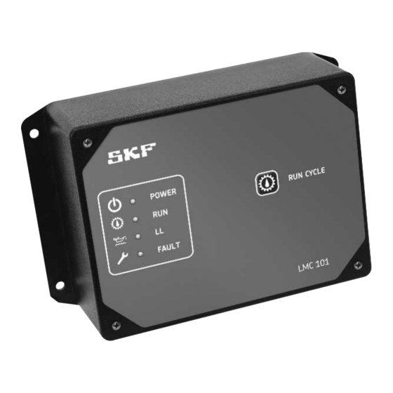
Controller mode Enclosure lid Description • In controller mode, lube cycle ends when Enclosure lid features: pressure switch, pressure transducer, or • Manual lubrication push button. Functionality piston detector actuates. • Four LEDs: LMC 101 controls both single line and –... -
Page 4: Pc Requirements
PC requirements Software installation Notice If PC does not have Microsoft .Net Framework 4.0 client installed, confirm PC meets these requirements before downloading .Net 4.0 client to PC: • Processor: 1 GHz Notice Notice Controller must be connected to • Memory: 512 MB Do not install LMC 101 software a PC that meets these requirements in •... -
Page 5: Controller Preparation
Controller preparation Notice LMC 101 software must be installed on a PC with a USB port prior to proceeding in this section. 1 Disconnect power supply to LMC 101. 2 Remove LMC 101 cover to expose printed circuit board. 3 Connect USB cable from PC to USB port on circuit board. -
Page 6: Controller Configuration
Controller configuration Notice LMC 101 can only be configured via USB cable to a PC that meets all PC requirements listed on page 4. 1 From main screen, click Program Controller button. Fig. 1 2 LMC 101 configuration window 2.1 In Customer field, enter name of your organization. - Page 7 Menu bar 3 On menu bar across top of window (fig. 2), three options are displayed - File, Clock, and Units. 3.1 Clicking on File displays: 3.1.1 Open file - allows user to select existing LMC 101 account settings for editing and/or downloading to another controller.
- Page 8 Left side menu In left side menu, four options will be listed - Location, System, Single-line, and alarms. Step 2 on page 6, covers default selection location. 4 System displays: 4.1 System type - drop menu to define system as: ·...
- Page 9 5 Prelube drop menu defines lubrication cycling option upon controller power up. · Always – a prelube cycle will always occur during power up. · After 3hr off – a prelube cycle will only occur when power has been off for longer than 3 hours.
- Page 10 7 Selecting pressure switch radio button activates: 7.1 End of line – allows use of a second pressure switch at end of lube supply line to complete lubrication cycle. W A R N I N G A pressure switch or transducer must still be used at pump in End of Line systems to prevent pressure build up.
- Page 11 8 Selecting pressure transducer radio button activates: Notice If pressure transducer option is selected, a pressures option will display on left side menu. Notice A pressure switch or transducer must still be used at pump in End of Line systems to prevent pressure build up.
- Page 12 9 Clicking on pressure displays: 9.1 Pressure to insure injector vent – At start of lube cycle, pressure reading from transducer must be at or below this level. If using an End of Line pressure transducer, reading is taken from this transducer.
- Page 13 10 Clicking on alarms displays: 10.1 Low level fault radio buttons – indicates that reservoir is low or empty. · No more lube cycles after low level alarm – no more lube cycles will occur after a low level alarm. ·...
- Page 14 Progressive systems 1 Clicking on system displays: 1.1 System type - drop menu that defines system for controller as: · Single-Line · Progressive. Notice If system is single line, return to step 1 on page 8. 1.2 Pause time – sets time spans between lube cycles.
- Page 15 2 Clicking on Progressive will display Timer and Controller radio buttons: 2.1 Timed – Amount of time that pump will be on. Fig. 12 2.2 Proximity switch – proximity switch actuation ends lube cycle. 2.3 Proximity - Number of proximity switch actuations per cycle.
-
Page 16: Controller History
Controller history 1 From main screen, click history button. The controller history window will display (fig. 15). 2 Each button on right side of window will produce a different type of history report. For all reports: · each event will be time and date stamped. -
Page 17: Firmware Update
Firmware update Notice Only perform these steps when notified of firmware updates. 1 Remove power from LMC 101. 2 Remove controller cover. 3 Attach LMC 101 to PC via USB cable. Controller’s Run light will blink for 13 seconds. 4 Launch Firmware Updater Utility on PC. Fig. -
Page 18: Controller Installation
Notice outputs, and connection polarity. Relieve tensile force on cables 1 Route the 86535 connection cables from outside of housing. through the cable glands (4 and 5) on the bottom of the enclosure (8). Fig. 17... - Page 19 Fig. 18 Dimensions 6.75 in. 171,5 mm 3.5 in. 88,9 mm 7.29 in. Ø 0.19 in. 185,2 mm 4,8 mm 1.50 in. 1.50 in. 38,1 mm 38,1 mm 1.196 in. 30,37 mm 1.16 in. 29,464 mm 4.72 in. 5.62 in. 119,9 mm 142,8 mm...
-
Page 20: Field Connections
Fig. 19 Field connections - wiring diagram for single-line system using pressure switches Outputs From motor battery Inputs Port Switch Wire Motor Pressure Transducer Normal open USB data port Switch Power Alarm output Normal closed source (+) Jumper Solenoid Fuse - size Ground (-) according to use Jumper connects (+) battery power to positive terminal of alarm contact. - Page 21 Fig. 20 Field connections - wiring diagram for single-line system using 4-20 mA pressure transducers Outputs From motor battery Inputs Port Switch Wire Motor Pressure Transducer Normal open USB data port Switch Power Alarm output Normal closed source (+) Jumper Solenoid Fuse - size Ground (-)
- Page 22 Fig. 21 Field connections - wiring diagram for single-line system using 1-6 V pressure transducers Outputs From motor battery Inputs Port Switch Wire Motor Pressure Transducer Normal open USB data port Switch Power Alarm output Normal closed source (+) Jumper Solenoid Fuse - size Ground (-)
- Page 23 Fig. 22 Field connections - wiring diagram for progressive system using piston detector Outputs From motor battery Inputs Port Switch Wire Motor Pressure Transducer Normal open USB data port Switch Power Alarm output Normal closed source (+) Jumper Solenoid Fuse - size Ground (-) according to use Jumper connects (+) battery power to positive terminal of alarm contact.
- Page 24 Every care has been taken to ensure the accuracy of the information contained in this publication but no liability can be accepted for any loss or damage whether direct, indirect or consequential arising out of the use of the information contained herein. SKF PUB LS/I4 15625 EN.R1 · June 2015 · FORM 404416C skf.com...
Need help?
Do you have a question about the 86535 and is the answer not in the manual?
Questions and answers