
Subscribe to Our Youtube Channel
Related Manuals for SKF ST-102


Summary of Contents for SKF ST-102
- Page 1 Assembly Instructions SKF ST-102 SLC CONTROLLER (11500613) Date: 8.6.2022 Document no.: ST-102 SLC Version: 1D Read this manual before installing or commissioning the product and keep it at hand for later reference!
- Page 2 Product Specialist SKF Lubrication Management Electronic Manufacturer: Oy SKF Ab Finland Teollisuustie 6 40951 Muurame FINLAND UK Declaration of Conformity pursuant to the Electromagnetic Compatibility Ordinance 2016 No. 1091 The manufacturer hereby declares under its sole responsibility conformity of the product described below with all relevant harmonization legislation of the United Kingdom at the time of placing on the market.
-
Page 3: Masthead
The instructions contain no statements regarding the warranty or liability for defects. That information can be found in our General Terms of Payment and Delivery. Training We conduct detailed training in order to enable maximum safety and efficiency. We recommend taking advantage of this training. For further information, contact your authorized SKF dealer or the manufacturer. -
Page 4: Table Of Contents
3. Cleaning ....................................11 Basics ....................................11 Interior cleaning ................................... 11 Exterior cleaning .................................. 11 4. SKF ST-102 SLC controller ............................... 12 Operation ..................................... 12 4.1.1 Indicators above the function button .......................... 13 4.1.2 Button functions ................................. 14 ST-102 SLC controller components ............................. 15 Changing lubrication system settings from the circuit board 3 operation mode .............. -
Page 5: Safety Alerts, Visual Presentation, And Layout
Safety alerts, visual presentation, and layout While reading these instructions, you will encounter various symbols, illustrations, and text layouts intended to help you navigate and understand the instructions. Their meaning is explained below. Safety alerts: Activities that present specific hazards (to life and limb or possible damage to property) are indicated by safety alerts. Always be sure to follow the instructions given in the safety alerts. -
Page 6: Safety Instructions
" Unauthorized modifications and changes can have an unpredictable effect on safety and operation. Unauthorized modifications and changes are therefore prohibited. Only original SKF spare parts and SKF accessories may be used. " Any unclear points regarding proper condition or correct assembly/operation must be clarified. Operation is prohibited until issues have been clarified. -
Page 7: Persons Authorized To Use The Product
Persons authorized to use the product Operator A person who is qualified by training, knowledge and experience to carry out the functions and activities related to normal operation. This includes avoiding possible hazards that may arise during operation. Specialist in mechanics Person with appropriate professional education, knowledge and experience to detect and avoid the hazards that may arise during transport, installation, start-up, operation, maintenance, repair and disassembly. -
Page 8: Notes On Ce Marking
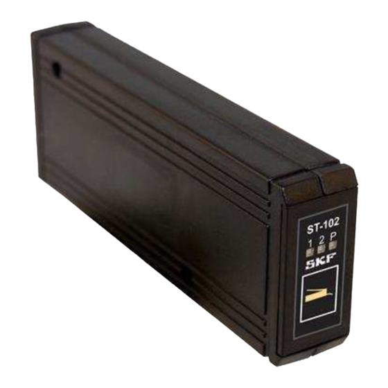
Fig. 1 Example- type plate from the ST102 V2.0 controller (11500610). Jumper settings can be different in each model! Notes on CE marking CE marking is effected following the requirements of the applied directives requiring a CE marking: " 2014/30/EC Electromagnetic Compatibility "... -
Page 9: Assembly, Maintenance, Fault, Repair
Assembly, maintenance, fault, repair Prior to the start of this work, all relevant persons must be notified of it. At a minimum, the following safety measures must be taken before any work is done: " Unauthorized persons must be kept away "... -
Page 10: Delivery, Returns, Storage
2. Delivery, returns, storage Delivery After receipt of the shipment, it must be inspected for any shipping damage and for completeness according to the shipping documents. Immediately inform the transport carrier of any shipping damage. The packaging material must be preserved until any discrepancies are resolved. -
Page 11: Cleaning
3. Cleaning Basics Cleaning should be carried out in accordance with the operator's own company rules, and cleaning agents and devices and the personal protective equipment to be used should likewise be selected in accordance with those rules. Only cleaning agents compatible with the materials may be used for cleaning. Completely remove any cleaning agent residue left on the product and rinse with clear water. -
Page 12: Skf St-102 Slc Controller
The ST-102 SLC controller includes a power failure memory. Therefore, if there is a power outage or break happens, the program will continue from the stage at which it was when the outage occurred. -
Page 13: Indicators Above The Function Button
4.1.1 Indicators above the function button Status Meaning Lubrication interval 3 line 1 was pressurised last Indicator 1 is lit Indicators 1 and P are on Line 1 is being pressurised. Pump is running. Indicator 1 is flashing Pulse alarm in the progressive system. Indicator 2 is flashing Pulse alarm from 2 cycle switch in the Progressive mode 2 system... -
Page 14: Button Functions
Pressing the function button when the program has started pressurization will interrupt/stop pressurization once. Controller will start counting the lubrication cycle from zero like as if pressurization had been completed as normal. Controller state Action Lubrication interval Initiate extra lubrication Pressurization Interrupt / stop pressurization Alarm Reset alarm ST-102 SLC function button... -
Page 15: St-102 Slc Controller Components
ST-102 SLC controller components ST-102 SLC controller components Position Component Function Function button Selecting functions Connector Function button connector Selector switch Program selector switch Selector switch Program selector switch Selector switch Program selector switch Selector switch Program selector switch Selector switch... -
Page 16: Changing Lubrication System Settings From The Circuit Board 3 Operation Mode
Changing lubrication system settings from the circuit board 3 operation mode Changes in the ST-102 SLC controller9s circuit board settings will take effect when the controller is powered off and on. It is recommended to change the settings when the controller is powered off, which means that the changes will take effect when the controller is powered on. - Page 17 Meaning Progressive <Mode 1= - lubrication functionality. Closed Closed Open / Open / / On / On Pump low level NC. Progressive <Mode 1= - lubrication functionality. Closed Closed Closed Open / / On / On / On Pump low level NO. Progressive <Mode 1= - lubrication functionality.
- Page 18 Closed Lubrication system settings can be changed using the function button. Open Not used with ST-102 SLC controller NOTE When the selector switch J9 is closed, only the function button can be used for setting lubrication parameters. Circuit board rotary switches SW1 and SW2 must be set to zero (0). If not, all indicators in the control panel will flash in succession and the lubrication program will not start.
-
Page 19: Changing Lubrication Parameter Settings Using The Function Button
Changing lubrication parameter settings using the function button The function button allows users to set the lubrication interval, maximum pressurization time and, in progressive systems, the required number of lubrication pulses. 4.4.1 Setting the lubrication cycle Lubrication cycle refers to the interval in which all lubrication points get lubricated. Press the function button for approximately 5 seconds. - Page 20 If the selector switch J8 is set to position Lubrication interval counting: input pulses (see chapter 2.3) the current set value of the lubrication cycle can be found in the following table. Number of Lubrication cycle flashes (pulses) To increase the lubrication cycle setting by one increment, briefly press the function button. When the highest setting is reached, the setting cycle starts from the beginning.
-
Page 21: Setting The Maximum Pressurization Time
4.4.2 Setting the maximum pressurization time Depending on the operating mode maximum pressurization time is the time that pumping is on when lubricated or a time-out limit if lubrication monitoring fails. See chapter 2.3. Press the function button until indicator 2 starts flashing rapidly (approximately 10 seconds). Now the maximum pressurization time can be set. -
Page 22: Setting The Progressive Distributor Pulse Count Setting
4.4.3 Setting the progressive distributor pulse count setting The pulse count setting can only be changed if the system is in the progressive lubrication operating mode, Progressive or Progressive mode 2. See chapter 2.3. Press the function button until indicators 1 and 2 start flashing rapidly (approximately 15 seconds). Now the pulse count can be set. -
Page 23: Electrical Connections
Electrical connections 4.5.1 Power supply and connections to the lubrication pump (X3) Connector X3 Electrical connections, Molex connector (X3) Connector Signal X3:1 X3:2 Supply voltage (+), 12 V DC or 24 V DC X3:3 Supply voltage (3), 0 V DC X3:4 X3:5 Piston detector 1 (+) -
Page 24: Extra Button Input (J5)
4.5.2 Extra button input (J5) When the contact of the external switch or button connected to the J5 connector is closed, the control system goes to the interlocking mode. This means that automatic lubrication and lubrication interval counting are suspended. The circuit board LED (D8) flashes once a second. When the contact is opened, lubrication interval counting will resume and the action connected to the current program phase will be initiated. -
Page 25: Technical Specifications
Technical specifications 330...+80 °C Operating temperature range Protection class IP30 Dimensions 160 x 26 x 60 mm (l x w x h) 12 or 24 V DC (10.5&32 V DC) Operating voltage Power consumption Depends on the lubrication system being controlled, 0...4 A Fuse Self-resetting fuse, 4 A, on the circuit board Control inputs... -
Page 26: Troubleshooting Table
Check the lubrication system9s Indicator P is flashing. Reservoir low level alarm troubleshooting instructions. Lubricant reservoir empty Contact information Oy SKF Ab P.O. Box 80 (Teollisuustie 6) FI-40951 MUURAME FINLAND Tel. +358 (0) 207 400 800 Fax. +358 (0) 207 400 899... -
Page 27: Appendix
5. Appendix Declarations and certificates Electrical example connection diagrams... -
Page 28: Electrical Circuit Diagram, Progressive / P203
5.2.1 Electrical circuit diagram, Progressive / P203... -
Page 29: Electrical Circuit Diagram, Progressive / Clp
5.2.2 Electrical circuit diagram, Progressive / CLP... -
Page 30: Electrical Circuit Diagram, Progressive/Kfg(Kfgx3Fx1Xxxx99+924)
5.2.3 Electrical circuit diagram, Progressive/KFG(KFGX3FX1XXXX99+924) -
Page 31: Electrical Circuit Diagram,Progressive/Kfg(Kfgx3Mx1Axxg99+924)
5.2.4 Electrical circuit diagram,Progressive/KFG(KFGX3MX1AXXG99+924) -
Page 32: Electrical Circuit Diagram, Progressive / Minilube
5.2.5 Electrical circuit diagram, Progressive / Minilube... -
Page 35: Electrical Circuit Diagram, Progressive / Multilube
5.2.6 Electrical circuit diagram, Progressive / Multilube... -
Page 36: China Rohs Table
China RoHS Table Table 1...
Need help?
Do you have a question about the ST-102 and is the answer not in the manual?
Questions and answers