Sign In
Upload
Manuals
Brands
SKF Manuals
Controller
086502
SKF 086502 Manuals
Manuals and User Guides for SKF 086502. We have
4
SKF 086502 manuals available for free PDF download: Operating Instructions Manual
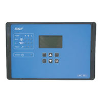
SKF 086502 Operating Instructions Manual (154 pages)
Lubrication Monitor Controller. For control of up to three pumps, each with an SKF Dual Line system containing one to three main lines.
Brand:
SKF
| Category:
Controller
| Size: 3 MB
Table of Contents
EU Declaration of Conformity
2
Table of Contents
4
Explanation of Symbols and Signs
6
1 Safety Instructions
8
General Safety Instructions
8
General Behavior When Handling the Product
8
Qualiied Technical Personnel
9
Electric Shock Hazard
10
Operation
10
Assembly/Maintenance/Malfunction/ Decommissioning/Disposal
10
Intended Use
11
Foreseeable Misuse
11
Disclaimer of Liability
12
Referenced Documents
12
Warning Labels on the Product
12
Residual Risks
13
2 Overview/System Description
14
System Design
18
2.2 General Design of a Dual Line
19
Pressure Switch
22
Lubrication System with Two Main Lines with One Differential Pressure Switch each
23
3 Technical Data
25
3.1 General Technical Data
25
Checking the Delivery
27
Storage
27
General Notes
27
4 Delivery, Returns, and Storage
27
Electronic and Electrical Devices
27
Setup and Attachment
28
Port Dimensions, Assembly Holes, and Minimum Mounting Dimensions
29
Opening the Controller Unit
30
Minimum Mounting Dimensions
30
Assembly of the Controller Unit
30
Electrical Connection 5.3.1 General
31
Terminal Board 100-240 VAC
32
Terminal Board 24 VDC
33
Connecting Wires
34
Line Routing
34
Load Switching Relay
35
Terminal Strip for Relay Outputs
36
Terminal Strip for Digital Inputs
37
Terminal Strip for Analog-Capable Inputs
37
Adding an Additional IO Connection to RS485 Interface
38
Note on the Rating Plate
39
Information on CE Marking
39
6 Coniguration by Operator/Local Admin
40
With PC Software
40
System Mode Half Cycle
41
Pressure Sensor EOL
41
Coniguration of the Controller Unit Via the Display on the Controller Unit
42
Overview States
42
Display and Control Elements of the Control Screen
42
Menu Navigation for Operators Without Password Access
46
Main Menu
50
Password Access
50
Password Change
54
Device Settings
55
Pump 1 Timings
56
Access
57
Local Admin (Setter) or Supervisor
58
With Password Access
58
Information
62
Dual Line System Examples
63
Valves and DDS50 Differential Pressure Switch
64
Lubrication System with EMU3 and 2 Pressure Switches
70
7 Operation/Decommissioning and Disposal
76
Recommissioning
77
Shutdown and Disposal
77
General Information
78
8 Maintenance
78
Maintenance Schedule
79
Battery Replacement
80
9 Malfunctions, Causes, and Remedies
81
Fuse Replacement
81
Fault LED
82
Dual Line Control Unit - Commissioning Malfunctions
86
System Malfunctions
87
Measures in Response to Malfunctions
90
11 System Configuration
92
Menu Navigation for System Coniguration - Pump Settings
92
Menu Navigation for System Coniguration - Zone Settings
94
With Two 3/2 Directional Zone Valves Per Zone
94
EM U3 Per Zone
96
EM U2 Per Zone
98
DU1 Auto-Change-Over Per Zone
100
MA/MP Per Zone
102
Menu Structure for System Coniguration
104
Amount of Pumps
105
Pump Settings
106
Zone 1 Settings (Main Line Basic Settings)
123
Zone 1 Settings with 3/2 Zone Directional Control Valves
127
Zone 1 Settings with EM U3
133
Zone 1 Settings with EM U2
141
Zone 1 Settings with DU1 or with MA/MP
147
Setting Parameters to Default
152
Resetting to Condition on Delivery
152
Advertisement
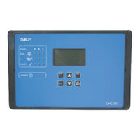
SKF 086502 Operating Instructions Manual (124 pages)
Lubrication Monitor Controller
Brand:
SKF
| Category:
Controller
| Size: 2 MB
Table of Contents
EU Declaration of Conformity in Accordance with Directive 2014/35/EU An- Nex IV on the Use of Electrical Equipment Within Certain Voltage Limits
2
Declaration of Conformity Pursuant to the Electrical Equipment (Safety) Regulations 2016 (No. 1101)
3
Masthead
4
Table of Contents
5
Explanation of Symbols and Signs
9
1 Safety Instructions
11
General Safety Instructions
11
General Behavior When Handling the Product
11
Qualified Technical Personnel
12
Electric Shock Hazard
13
Operation
13
Assembly, Maintenance, Faults, Decommissioning and Disposal
13
Foreseeable Misuse
14
Intended Use
14
Disclaimer of Liability
15
Referenced Documents
15
Warning Labels on the Product
15
Notes on the Type Plate
16
Note on UL Mark
16
Note on UKCA Marking
16
Note on China Rohs Marking
16
Note on CE Marking
16
Note on Pressure Equipment Directive 2014/68/EU
16
Residual Risk
17
2 Overview/System Description
18
LMC 301 Controller Unit
21
General Design of a Single-Line Centralized Lubrication System
22
Design of the Equipment
23
3 Technical Data
25
General Technical Data
25
4 Delivery, Returns, and Storage
27
Checking the Delivery
27
Return Shipments
27
Storage
27
5 Assembly
28
General
28
Setup and Attachment
28
Port Dimensions, Assembly Holes, and Minimum Mounting Dimensions
29
Opening the Controller Unit
30
Minimum Mounting Dimensions
30
Assembly of the Controller Unit
30
Electrical Connection
31
General
31
Terminal Board 100-240 VAC
33
Terminal Board 24 VDC
34
Line Routing
35
Connecting the Wires
35
Power Supply 100
36
Load Switching Relay
36
Terminal Strip for Relay Outputs
37
Terminal Strip for Digital Inputs
38
Terminal Strip for Analog-Capable Inputs
38
Adding an Additional IO Connection to RS485 Interface
39
6 Configuration by Operator/Local Admin
40
Configuration of the Controller Unit with PC Software
40
Configuration of the Controller Unit Via the Display on the Controller Unit
41
Structure of a Lubrication Cycle
41
States/Overview
42
Display and Control Elements of Control Screen
42
Menu Navigation for Operators Without Password Access
46
Menu Navigation for Local Admins with Password Access
48
Main Menu
50
General Setting Options Without (With) Password Access
51
Setting Options for Local Admins (Setters) with Password Access
53
Changing the Password
54
Device Settings
55
Pump 1 Timings
56
Operator Level Without Password Access
56
Local Admin (Setter) or Supervisor with Password Access
57
Information
60
Examples of Single-Line Systems
61
2-Zone Single-Line Centralized Lubrication System with 2/2 Directional Solenoid Valves and 1 Pressure Switch
62
2-Zone Single-Line Centralized Lubrication System with 3/2 Directional Solenoid Valves and 2 Pressure Switches
68
7 Operation/Decommissioning and Disposal
74
User-Configurable Setting Options
74
Temporary Shutdown
75
Recommissioning
75
Shutdown and Disposal
75
8 Maintenance
76
General
76
Maintenance Schedule
77
Battery Replacement
78
Software Update
78
9 Malfunctions, Causes, and Remedies
79
Fuse Replacement
79
Display of Error Notifications Via Fault LED
80
Display of Fault Notifications on the Screen
80
Controller Unit- Commissioning Malfunctions
84
System Malfunction
85
Measures in Response to Malfunctions
88
10 Spare Parts/Accessories
89
11 System Configuration
90
Menu Navigation for System Configuration - Pump Settings
90
Menu Navigation for System Configuration - Zone Settings
92
Menu Structure for System Configuration
94
Amount of Pumps
95
Setting the Pump
96
Zone 1 Settings (Main Line Settings)
112
Set Params to Default
121
Resetting to Condition on Delivery
121
12 China Rohs Table
122
SKF 086502 Operating Instructions Manual (116 pages)
Lubrication Monitor Controller
Brand:
SKF
| Category:
Controller
| Size: 2 MB
Table of Contents
Table of Contents
4
1 Safety Instructions
6
Explanation of Symbols and Signs
6
General Behavior When Handling the Product
8
General Safety Instructions
8
Qualiied Technical Personnel
9
Assembly/Maintenance/Malfunction/ Decommissioning/Disposal
10
Electric Shock Hazard
10
Operation
10
Foreseeable Misuse
11
Intended Use
11
Disclaimer of Liability
12
Referenced Documents
12
Warning Labels on the Product
12
Residual Risks
13
2 Overview/System Description
14
General Design of a Progressive Centralized Lubrication System with LMC 301 Controller
19
System Design
19
General
21
General Technical Data
21
3 Technical Data
21
Electronic and Electrical Devices
23
5 Assembly
24
General Information
24
Setup and Attachment
24
Port Dimensions, Assembly Holes, and Minimum Mounting Dimensions
25
Assembly of the Controller Unit
26
Minimum Mounting Dimensions
26
Opening the Controller Unit
26
Electrical Connection
27
Terminal Board 100 to 240 VAC
29
Terminal Board 24 VDC
30
Line Routing
31
Power Supply 100 to 240 V AC and 24 V DC
32
Load Switching Relay
32
Terminal Strip for Relay Outputs
33
Terminal Strip for Analog Inputs
34
Terminal Strip for Digital Inputs
34
Adding an Additional IO Connection to RS485 Interface
35
Note on the Rating Plate
36
Information on CE Marking
37
6 Coniguration by Operator/Local Admin
38
With PC Software
38
Coniguration of the Controller Unit Via the Display on the Controller Unit
39
Display and Control Elements of the Control Screen
41
Menu Navigation for Operators Without Password Access
44
Menu Navigation for Local Admins with Password Access
46
Changing the Password
52
Zone Progressive Centralized
60
7 Operation/Decommissioning and Disposal
67
Decommissioning and Disposal
68
Temporary Shutdown
68
General Information
69
8 Maintenance
69
Maintenance Schedule
70
Battery Replacement
71
Software Update
71
Fuse Replacement
72
9 Malfunctions, Causes, and Remedies
72
Progressive Control Unit - Commissioning Malfunctions
77
System Malfunctions
78
Feeder and System Malfunctions
81
Measures in Response to
84
10 Spare Parts/Accessories
85
11 System Coniguration
90
Menu Structure for System Coniguration
90
Amount of Pumps
91
Setting the Pump
92
Main Lines
93
Zone 1 Settings
107
(Main Line Settings)
107
Zone 2/Zone 3 Settings (Main Lines)
114
Setting Parameters to Default
115
Reset to Factory Settings
115
Advertisement
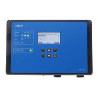
SKF 086502 Operating Instructions Manual (120 pages)
Lubrication monitor controller. For controlling three pumps, each with one- to three - line SKF Single Line centralized lubrication systems
Brand:
SKF
| Category:
Controller
| Size: 2 MB
Table of Contents
Table of Contents
4
Explanation of Symbols and Signs
6
1 Safety Instructions
8
General Safety Instructions
8
General Behavior When Handling the Product
8
Qualiied Technical Personnel
9
Electric Shock Hazard
10
Operation
10
Assembly/Maintenance/Malfunction /Decommissioning/Disposal
10
Intended Use
11
Foreseeable Misuse
11
Disclaimer of Liability
12
Referenced Documents
12
Warning Labels on the Product
12
Residual Risks
13
2 Overview/System Description
14
System Design
17
3 Technical Data
21
General
21
General Technical Data
21
Setup and Attachment
24
Port Dimensions, Assembly Holes, and Minimum Mounting Dimensions
25
Opening the Controller Unit
26
Minimum Mounting Dimensions
26
Assembly of the Controller Unit
26
Electrical Connection
27
Terminal Board 100 to 240VAC
29
Terminal Board 24 VDC
30
Power Supply 100 to 240 V AC
32
Load Switching Relay
32
Terminal Strip for Digital Inputs
34
Terminal Strip for Analog Inputs
34
Adding an Additional IO Connection to RS485 Daisy Chain
35
Note on the Rating Plate
36
Information on CE Marking
36
6 Coniguration by Operator/Local Admin
38
Coniguration of the Controller Unit with PC Software
38
Coniguration of the Controller Unit Via the Display on the Controller Unit
39
Display and Control Elements of the Control Screen
40
Menu Navigation for Operators Without Password Access
44
Menu Navigation for Local Admins with Password Access
46
General Setting Options Without (With) Password Access
49
Setting Options for Local Admins (Setters) with Password Access
51
Changing the Password
52
Single Line-Control System Examples
59
And 1 Pressure Switch
66
7 Operation/Decommissioning and Disposal
72
User-Conigurable Setting Options
72
Temporary Shutdown
73
Recommissioning
73
Decommissioning and Disposal
73
Fuse Replacement
77
Display of Error Messages Via
78
Display of Error Messages on
78
Flex-Control Unit -Commissioning
82
System Malfunctions
83
Measures in Response to Malfunctions
86
11 System Coniguration
88
Menu Navigation for System Coniguration - Pump Settings
88
Menu Navigation for System Coniguration - Zone Settings
90
Menu Structure for System Coniguration
92
Amount of Pumps
93
Setting the Pump
94
Zone 1 Settings (Main Line Settings)
110
Zone 2 Settings (Main Lines)
117
Setting Parameters to Default
118
Reset to Factory Settings
118
Advertisement
Related Products
SKF 086501
SKF 086500
SKF 086503
SKF THAP 030E
SKF 11500613
SKF 86535
SKF CAHB-10
SKF CAHB-20 Series
SKF CAHB-20E
SKF CAHB-21
SKF Categories
Water Pump
Lubrication systems
Measuring Instruments
Tools
Industrial Equipment
More SKF Manuals
Login
Sign In
OR
Sign in with Facebook
Sign in with Google
Upload manual
Upload from disk
Upload from URL