
Subscribe to Our Youtube Channel
Related Manuals for NXP Semiconductors MIMXRT1060-EVKB


Summary of Contents for NXP Semiconductors MIMXRT1060-EVKB
- Page 1 NXP Semiconductors Document identifier: MIMXRT1060-EVKBUM User Manual Rev. 0, 7 January 2022 MIMXRT1060-EVKB Board User Manual...
-
Page 2: Table Of Contents
2.16 M.2 connector and Wi-Fi/Bluetooth module................24 2.17 MFI interface..........................25 2.18 CAN interface........................25 2.19 Debug............................ 25 2.19.1 OpenSDA serial and debug adapter..................26 2.19.2 JTAG connector........................26 Appendix A Revision History................27 MIMXRT1060-EVKB Board User Manual, Rev. 0, 7 January 2022 User Manual 2 / 28... -
Page 3: Chapter 1 Overview
The MIMXRT1060-EVKB board provides a comprehensive platform for design and evaluation of most commonly used features of the NXP i.MX RT1060 application processor, in a small and low-cost package. MIMXRT1060-EVKB is an entry level development board, to familiarize user with the processor before investing a large amount of resources in more specific designs. -
Page 4: Kit Contents
® ® with NXP MCUs based on Arm Cortex -M cores. 1.3 Kit contents The table below lists the items included in the MIMXRT1060-EVKB kit. Table 3. Hardware kit contents Item Quantity MIMXRT1060-EVKB board USB Type A to micro-B cable... - Page 5 M o t io n Se n s o rs ARDUIN O SP DIF PIN Header PIN Header Wolfson WM8960 IN/ OUT Combo FX OS8700CQ M IC Figure 1. MIMXRT1060-EVKB block diagram MIMXRT1060-EVKB Board User Manual, Rev. 0, 7 January 2022 User Manual 5 / 28...
-
Page 6: Board Pictures
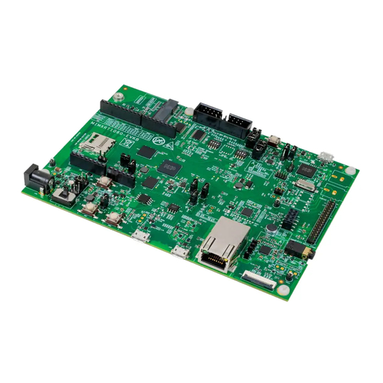
NXP Semiconductors Overview 1.5 Board pictures The figure below shows the top-side view of MIMXRT1060-EVKB. Figure 2. MIMXRT1060-EVKB top view MIMXRT1060-EVKB Board User Manual, Rev. 0, 7 January 2022 User Manual 6 / 28... - Page 7 NXP Semiconductors Overview The figure below shows the onboard jumpers and connectors on MIMXRT1060-EVKB. Figure 3. MIMXRT1060-EVKB jumpers and connectors MIMXRT1060-EVKB Board User Manual, Rev. 0, 7 January 2022 User Manual 7 / 28...
-
Page 8: Board Features
NXP Semiconductors Overview The figure below shows the LEDs and push buttons on MIMXRT1060-EVKB. Figure 4. MIMXRT1060-EVKB LEDs and push buttons 1.6 Board features The table below lists the features of MIMXRT1060-EVKB. Figure 2 shows different components of MIMXRT1060-EVKB. Table 4. MIMXRT1060-EVKB features... - Page 9 • Supports 24-pin FPC camera module connector, J46, to which the camera modules based on the MT9M114 or OV7725 sensors can be plugged in Table continues on the next page... MIMXRT1060-EVKB Board User Manual, Rev. 0, 7 January 2022 User Manual 9 / 28...
-
Page 10: Push Buttons
CAN signals to and from the processor 11 cm x 15 cm 4-layer board 1.7 Push buttons In addition to a Reset button for manually triggering a system reset, MIMXRT1060-EVKB supports 4 push buttons. The following table explains the push buttons on MIMXRT1060-EVKB. Figure 4 shows push buttons on MIMXRT1060-EVKB. -
Page 11: Jumpers
Jumpers (or shorting headers) are small connectors that allow to choose from two or more options available. Jumpers are installed during board assembly and do not require any changes. In MIMXRT1060-EVKB, all jumpers are 2/3-pin connectors with two settings: open and shorted. - Page 12 • Shorted: Audio codec is connected to the signal routed to SAI1_RXD i.MX RT1060 and audio main connector, J23 (default setting) Table continues on the next page... MIMXRT1060-EVKB Board User Manual, Rev. 0, 7 January 2022 User Manual 12 / 28...
-
Page 13: Leds
DCDC_3V3 1.10 LEDs MIMXRT1060-EVKB has light-emitting diodes (LEDs) to monitor system functions, such as power-on, reset, board faults, and so on. The information collected from LEDs can be used for debugging purposes. LEDs are highlighted in Figure 4. -
Page 14: Chapter 2 Functional Description
BOOT_MODE Switch, SW4[3:4], is used to select the boot mode on the MIMXRT1060-EVKB board. For each switch: • If the switch is ON, the value is '1'. • If the switch is OFF, the value is '0'. -
Page 15: Power Supply
2.3 Power supply MIMXRT1060-EVKB can be powered by any of the following (+5 V) sources: • External DC power supply connected to input power jack, J45 • USB 2.0 Micro-AB connector operating in Device mode, J48 • Micro-AB USB connector for OpenSDA, J1 A slider switch SW6 turns ON/OFF the 5 V external DC power supply connected to J45: •... - Page 16 NXP Semiconductors Functional description Figure 5. Power tree The following diagram shows the power control logic of the MIMXRT1060-EVKB board. • SNVS is powered first and then is switched on to enable external DC/DC to power up other power domains PMIC_REQ_ON •...
- Page 17 Power for GPIO in SDIO1 bank (1.8 V 1.65 1.95 mode) Power for GPIO in SDIO2 bank (3.3 V NVCC_SD1 mode) Table continues on the next page... MIMXRT1060-EVKB Board User Manual, Rev. 0, 7 January 2022 User Manual 17 / 28...
-
Page 18: Clocks
• Up to 512 Mb per each Chip Select (CS) and up to 4x CS On MIMXRT1060-EVKB, SEMC is connected to 256 Mbit SDRAM (U16), operating at 3.3 V with maximum frequency 166 MHz. is input/output when the processor writes data to the SDRAM, it outputs the DQS in the center of the data it is writing. -
Page 19: Sdhc
, as explained in Table 10 ONOFFONOFF 2.7 PCB information The MIMXRT1060-EVKB board uses the standard 4-layer technology. The material used is FR-4. The PCB stack-up information is shown in the following table. Table 15. Board stack-up information Layer Description... -
Page 20: Flexspi Interface
Table 2.8.2 QSPI NOR flash memory MIMXRT1060-EVKB supports QSPI as the primary system boot source. By default, the QSPI NOR flash memory is enabled on the board. The table below describes the QSPI NOR flash memory supported on MIMXRT1060-EVKB. Table 17. QSPI NOR flash memory... -
Page 21: Ethernet Interface
• Low-speed (LS) rate of 1.5 Mbit/s • Full-speed (FS) rate of 12 Mbit/s • High-speed (HS) rate of 480 Mbit/s The OTG controllers can operate in Host mode and Device (Peripheral) mode. The table below describes the MIMXRT1060-EVKB USB connectors. Table 18. USB ports... -
Page 22: Arduino Connectors
Table 21. J17 pinouts Pin function Target processor port D8/CLKO/ICP1 GPIO_AD_B0_03 D9/OC1A/PWM GPIO_AD_B0_02 D10/SPI_CS GPIO_SD_B0_01 D11/OC2A/PWM/SPI_MOSI GPIO_SD_B0_02 D12/SPI_MISO GPIO_SD_B0_03 D13/SPI_CLK GPIO_SD_B0_00 Table continues on the next page... MIMXRT1060-EVKB Board User Manual, Rev. 0, 7 January 2022 User Manual 22 / 28... -
Page 23: Camera Interface
However, for the final product design, it is recommended to adjust DCDC output or add level shifter. 2.14 6-axis digital sensor MIMXRT1060-EVKB supports motion sensing with NXP FXOS8700CQ (U12) 6-axis sensor with integrated linear accelerometer and magnetometer. FXOS8700CQ is a small, low-power, 3-axis, linear accelerometer and 3-axis, magnetometer combined into a single package. -
Page 24: Lcd Interface
• 8/16/18/24/32 bit LCD data bus support available depending on I/O MUX options • Programmable timing and parameters for DOTCLK LCD interfaces MIMXRT1060-EVKB includes 1x40 + 1x 6 LCD connector, J49. The LCD panels can be connected at J49 (A1-A40) and Capacitive Touch Panels (CPT) can be connected at J49 (B1-B6). -
Page 25: Mfi Interface
Connected to processor signal WIFI_RST_B 2.17 MFI interface MIMXRT1060-EVKB supports 2x4 pin MFI connector, J24. The MFI connector is connected to the target processor through the LPI2C3 interface signals. 2.18 CAN interface i.MX RT1060 supports Flexible Controller Area Network (FLEXCAN) module, which is a communication controller implementing the CAN protocol according to the CAN 2.0B protocol specification. -
Page 26: Opensda Serial And Debug Adapter
NXP Semiconductors Functional description • LPC4322 microcontroller that can be used as CMSIS DAP on MIMXRT1060-EVKB. The CMSIS DAP provides low speed debug functionality for i.MX RT1060 2.19.1 OpenSDA serial and debug adapter The MIMXRT1060-EVKB board includes an OpenSDA serial and debug adapter. OpenSDA provides a bridge between the computer (or other USB hosts) and the embedded target processor, which can be used for debugging, flash programming, and serial communication, all over a simple USB cable. -
Page 27: Appendix A Revision History
The table below summarizes the revisions to this document. Table 25. Revision history Revision Date Topic cross-reference Change description 7 Jan 2022 Rev. 0 Initial public release MIMXRT1060-EVKB Board User Manual, Rev. 0, 7 January 2022 User Manual 27 / 28... - Page 28 Right to make changes - NXP Semiconductors reserves the right to make changes to information published in this document, including without limitation specifications and product descriptions, at any time and without notice. This document supersedes and replaces all information supplied prior to the publication hereof.
Need help?
Do you have a question about the MIMXRT1060-EVKB and is the answer not in the manual?
Questions and answers