Table of Contents
Advertisement
Quick Links
MIMXRT1040-EVKUM
MIMXRT1040-EVK Board User Manual
Rev. 0 — 13 January 2023
Document information
Information
Content
Keywords
MIMXRT1040-EVKUM, i.MX RT1040 processor, MIMXRT1040-EVK board,
QSPI flash, audio interface, 3-axis accelerator, S/PDIF, CAN, OpenSDA,
JTAG, LPUART, LPC4322 microcontroller
Abstract
This document provides detailed information about MIMXRT1040-EVK board
interfaces, power supplies, clocks, connectors, jumpers, user buttons, and
LEDs.
User manual
Advertisement
Table of Contents

Subscribe to Our Youtube Channel
Related Manuals for NXP Semiconductors MIMXRT1040-EVKUM


Summary of Contents for NXP Semiconductors MIMXRT1040-EVKUM
- Page 1 User manual Document information Information Content Keywords MIMXRT1040-EVKUM, i.MX RT1040 processor, MIMXRT1040-EVK board, QSPI flash, audio interface, 3-axis accelerator, S/PDIF, CAN, OpenSDA, JTAG, LPUART, LPC4322 microcontroller Abstract This document provides detailed information about MIMXRT1040-EVK board interfaces, power supplies, clocks, connectors, jumpers, user buttons, and...
-
Page 2: Overview
MIMXRT1040-EVKUM NXP Semiconductors MIMXRT1040-EVK Board User Manual Overview The MIMXRT1040-EVK board provides a comprehensive platform for design and evaluation of most commonly used features of the NXP i.MX RT1040 application processor, in a small and low-cost package. This board is an entry-level development board, meant to familiarize users with the processor before investing a large amount of resources in more specific designs. -
Page 3: Related Documentation
MIMXRT1040-EVKUM NXP Semiconductors MIMXRT1040-EVK Board User Manual Table 1. Acronyms and abbreviations ...continued Term Description Universal Serial Bus LPUART Low Power Universal Asynchronous Receiver Transmitter 1.2 Related documentation The table below lists and explains the additional documents and resources that can be referred to if more information about MIMXRT1040-EVK board is required. -
Page 4: Block Diagram
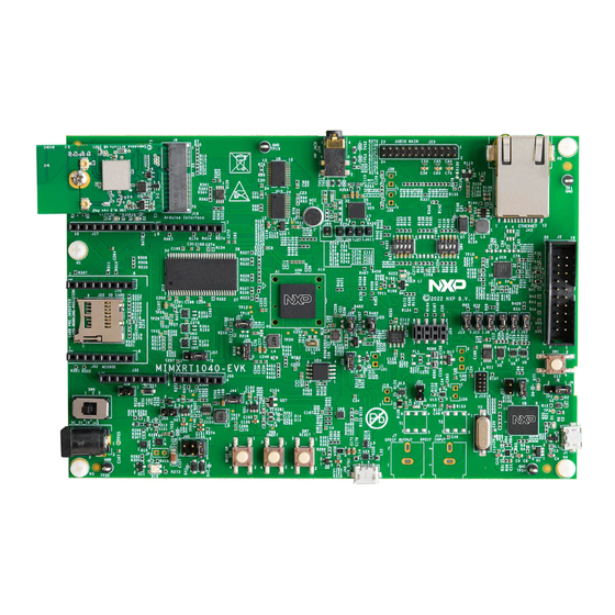
MIMXRT1040-EVKUM NXP Semiconductors MIMXRT1040-EVK Board User Manual 1.4 Block diagram The figure below shows the MIMXRT1040-EVK block diagram. Ethernet x1 (RMII) USB OTG CAN x1 TJA1057GT/3 100Base-TMicrel KSZ8081 4.3" TFT 480 x 272 RMII DISP USB OTG1 QSPI FLASH FlexSPI... - Page 5 MIMXRT1040-EVKUM NXP Semiconductors MIMXRT1040-EVK Board User Manual (Microphone) (HP Jack) (SDRAM) (M.2 Connector) (Audio connector) (Bluetooth LED) (Ethernet) (WiFi LED) (JTAG) J17, J16 SW3 and SW4 (Arduino Connectors) (boot mode switches) (Mikroe-click (User LED) connector) SD Card Slot (LPI2C3) (Reset)
- Page 6 MIMXRT1040-EVKUM NXP Semiconductors MIMXRT1040-EVK Board User Manual J35, J36, J37, J41 J11 J9 Figure 3. Jumpers on top side of the MIMXRT1040-EVK board MIMXRT1040-EVKUM All information provided in this document is subject to legal disclaimers. © 2023 NXP B.V. All rights reserved.
-
Page 7: Board Features
MIMXRT1040-EVKUM NXP Semiconductors MIMXRT1040-EVK Board User Manual The figure below shows the bottom side of the MIMXRT1040-EVK board. Figure 4. Bottom view of MIMXRT1040-EVK board (LCD connector) (LCD connector B1-B6) 1.6 Board features The table below lists the features of the MIMXRT1040-EVK board. -
Page 8: Connectors
MIMXRT1040-EVKUM NXP Semiconductors MIMXRT1040-EVK Board User Manual Table 4. MIMXRT1040-EVK board features ...continued MIMXRT1040-EVK board Processor feature Description feature used FlexSPI FlexSPI • 8 MB on-board QSPI NOR flash memory (3.3V) - as boot device Ethernet RMII interface • Supports one 10Base-T/100Base-TX Ethernet port through one RJ45 connector with link and activity status One USB 2.0 OTG... -
Page 9: Jumpers
MIMXRT1040-EVKUM NXP Semiconductors MIMXRT1040-EVK Board User Manual Table 5. MIMXRT1040-EVK board connectors ...continued Part Connector type Description Reference section identifier USB 2.0 Micro- Debug USB for OpenSDA. Provides 5 V power Section 2.19.1 AB connector supply to the board and CMSIS DAP debug support. - Page 10 MIMXRT1040-EVKUM NXP Semiconductors MIMXRT1040-EVK Board User Manual Table 6. MIMXRT1040-EVK board jumpers Part Jumper Description Jumper settings identifier type • Open: Isolates the onboard processor from OpenSDA JTAG J3, J4 1x2 header OpenSDA JTAG debug interface interface • Shorted: Connect the TDO_SWO and JTAG_TDI_L signals from OpenSDA to i.MX RT1040 (default setting)
- Page 11 MIMXRT1040-EVKUM NXP Semiconductors MIMXRT1040-EVK Board User Manual Table 6. MIMXRT1040-EVK board jumpers ...continued Part Jumper Description Jumper settings identifier type • Shorted (default setting) 1x2 header Arduino reset • Open: Isolates reset signal from RT1040 and Arduino interface 1x2 header Power domain •...
-
Page 12: Push And Slide Buttons
MIMXRT1040-EVKUM NXP Semiconductors MIMXRT1040-EVK Board User Manual 1.9 Push and slide buttons The MIMXRT1040-EVK board has four push buttons and one slide button. The following table explains the push and slide buttons on the MIMXRT1040-EVK board. Figure 2 shows push and slide buttons on the MIMXRT1040-EVK board. -
Page 13: Functional Description
MIMXRT1040-EVKUM NXP Semiconductors MIMXRT1040-EVK Board User Manual Table 8. MIMXRT1040-EVK board LEDs ...continued Part identifier LED color LED name Description (When LED in ON) Wi-Fi LED Indicates the Wi-Fi status Functional description 2.1 Processor The i.MX RT1040 is a new processor family featuring NXP advanced implementation of the Arm Cortex-M7 core. -
Page 14: Power Supply
MIMXRT1040-EVKUM NXP Semiconductors MIMXRT1040-EVK Board User Manual For SD boot, the card detect signal (SD_CD_SW), from the SD card socket to the processor must be low. The signal is low when an SD card is detected in the socket. The SD_CD_SW signal is high when no SD card is present or SD card is not detected in the socket. - Page 15 MIMXRT1040-EVKUM NXP Semiconductors MIMXRT1040-EVK Board User Manual Figure 5. Power tree The following diagram shows the power control logic of the MIMXRT1040-EVK board. • SNVS is powered first and then PMIC_REQ_ON is switched on to enable external DC- DC to power up other power domains •...
- Page 16 MIMXRT1040-EVKUM NXP Semiconductors MIMXRT1040-EVK Board User Manual Table 11. MIMXRT1040-EVK board power supplies ...continued Power source Manufacturing Power supply rail Description part number From external 5V_USB_OTG (5 V) One of the three power source options for producing source through 5V_SYS supply.
- Page 17 MIMXRT1040-EVKUM NXP Semiconductors MIMXRT1040-EVK Board User Manual Table 11. MIMXRT1040-EVK board power supplies ...continued Power source Manufacturing Power supply rail Description part number MP2144GJ DCDC_3V3 (3.3 V) Switching Voltage Regulator, used to power: (Monolithic (Current 2 A • Produces SENSOR_3V3 supply, which is used to...
-
Page 18: Clocks
MIMXRT1040-EVKUM NXP Semiconductors MIMXRT1040-EVK Board User Manual Table 11. MIMXRT1040-EVK board power supplies ...continued Power source Manufacturing Power supply rail Description part number UM1750 P3V3_SDA (3.3 V) • Supplies 3.3 V power to Freelink interface (LPC4322 S-00 (Union JET100). It is also used to change the voltage level of Semiconductor) Freelink interface signals going to / coming from i.MX... -
Page 19: Sdhc
MIMXRT1040-EVKUM NXP Semiconductors MIMXRT1040-EVK Board User Manual 2.5 SDHC i.MX RT1040 supports one Ultra Secured Digital Host Controller (uSDHC) module for SD/eMMC interface, uSDHC. The uSDHC interface provides the interface between the host system and the SD/SDIO/MMC cards. The module acts as a bridge, passing host bus transactions to the SD/SDIO/MMC cards by sending commands and performing data accesses to/from the cards. -
Page 20: Ethernet Interface
MIMXRT1040-EVKUM NXP Semiconductors MIMXRT1040-EVK Board User Manual Table 14. QSPI NOR flash memory Part identifier Part number Description Boot settings W25Q64JVSSIQ • Type: On-board QSPI NOR flash SW4 [1:4] = OFFOFFONOFF memory (Windbond Electronics) • Density: 64 Mbit (8 MB) • Operating voltage: 3.3 V (FLASH_VCC) Note: For more details about i.MX RT1040 boot device settings, see... -
Page 21: Audio Connector
MIMXRT1040-EVKUM NXP Semiconductors MIMXRT1040-EVK Board User Manual Communication between the audio codec and target processor is enabled using I2C (for control signals) and SAI (for data signals). 2.9.2 Audio connector The MIMXRT1040-EVK board supports a 2x12-pin connector, J23 for connecting an external audio device. -
Page 22: Mikrobus Socket
MIMXRT1040-EVKUM NXP Semiconductors MIMXRT1040-EVK Board User Manual Table 16. J17 pinouts Pin number Name Target processor port D8/CLKO/ICP1 GPIO_B1_14 D9/OC1A/PWM GPIO_B1_15 D10/SPI_CS GPIO_SD_B0_01 D11/OC2A/PWM/SPI_MOSI GPIO_SD_B0_02 D12/SPI_MISO GPIO_SD_B0_03 D13/SPI_CLK GPIO_SD_B0_00 AREF (DCDC_3V3) D14/I2C_SDA GPIO_AD_B1_01 D15/I2C_SCL GPIO_AD_B1_00 The table below shows J32 pinouts. -
Page 23: 3-Axis Accelerometer
MIMXRT1040-EVKUM NXP Semiconductors MIMXRT1040-EVK Board User Manual The MIMXRT1040-EVK board has a mikroBUS socket with two 1x8 position receptacles, J62 and J70. The figure below shows the silkscreen markings and pinouts of the mikroBUS socket connectors with explanation. Analog PWM output... -
Page 24: Connector
MIMXRT1040-EVKUM NXP Semiconductors MIMXRT1040-EVK Board User Manual The major features of eLCDIF are as follows: • Bus master interface to source frame buffer data for display refresh • 8/16/18/24/32 bit LCD data bus support available depending on I/O MUX options •... -
Page 25: Wi-Fi/Bluetooth Module
MIMXRT1040-EVKUM NXP Semiconductors MIMXRT1040-EVK Board User Manual Table 19. M.2 mini card connector (J8) pinouts ...continued M.2 mini card pin M.2 mini card Connection details signal name UART_RTS Connected to the processor through voltage translator, 74AVC8T245PW (U9), via signal, BT_UART_RTS... -
Page 26: How To Bring Up The Murata Type 1Xk Module
MIMXRT1040-EVKUM NXP Semiconductors MIMXRT1040-EVK Board User Manual Table 20. Wi-Fi + Bluetooth card Parameter Description Manufacturer MuRata Part number LBEE5CJ1XK Chipset NXP IW416 WLAN standards 802.11a/b/g/n, Wi-Fi 4 Bluetooth standards Bluetooth 5.2 specification Type 1XK is a small high-performance module based on the NXP IW416 combo chipset. -
Page 27: Hardware Requirements
MIMXRT1040-EVKUM NXP Semiconductors MIMXRT1040-EVK Board User Manual • The software requirements • Steps to run the Wi-Fi demo application 2.18.1 Hardware requirements • MIMXRT1040 EVK board • USB cable (Micro B) • Murata type 1XK module Figure 9 shows how to connect the Murata type 1XK module to the MIMXRT1040 EVK board via the M.2 interface. -
Page 28: Running A Sample Wi-Fi Demo Application
MIMXRT1040-EVKUM NXP Semiconductors MIMXRT1040-EVK Board User Manual 2. Download the MIMXRT1040 SDK package, from MCUXpresso SDK Builder shown in Figure Figure 11. Downloading SDK Package 2.18.3 Running a sample Wi-Fi demo application 1. Open the MCUXpresso IDE 11.6.0, and add the downloaded SDK package to... - Page 29 MIMXRT1040-EVKUM NXP Semiconductors MIMXRT1040-EVK Board User Manual Figure 13. Importing an SDK example 3. Select wifi_example from the list, and select wifi_cli as an example, and click Finish, as shown in Figure Figure 14. Selecting WiFi example 4. Select the evkmimxrt1040_wifi_cli project, click Build to compile, and then...
- Page 30 MIMXRT1040-EVKUM NXP Semiconductors MIMXRT1040-EVK Board User Manual 5. The image download has been completed, as shown in Figure Figure 16. Downloading the image 6. Connect a micro USB cable between the PC host and CMSIS DAP USB port on the board and open a serial terminal with the following settings: •...
-
Page 31: Debug
MIMXRT1040-EVKUM NXP Semiconductors MIMXRT1040-EVK Board User Manual Figure 17. Running the demo 2.19 Debug The MIMXRT1040-EVK board consists of the i.MX RT1040 processor and the LPC4322JET100 microcontroller, each having a dedicated debug connector: • JTAG connector J2 for debugging i.MX RT1040 •... -
Page 32: Jtag Connector
MIMXRT1040-EVKUM NXP Semiconductors MIMXRT1040-EVK Board User Manual To update the OpenSDA firmware, press the SW1 and power on the board. There is a disk named MAINTENANCE. Drag/drop the new firmware to the MAINTENANCE and re-power the board. The firmware is updated. -
Page 33: Revision History
MIMXRT1040-EVKUM NXP Semiconductors MIMXRT1040-EVK Board User Manual On the MIMXRT1040-EVK board, the i.MX RT1040 CAN ports are available for external connection through CAN connector, J42 (DNP). One high-speed CAN transceiver (NXP TJA1057GT/3) provides an interface for the CAN ports to send and receive CAN signals to and from the processor. -
Page 34: Legal Information
NXP Semiconductors. In the event that customer uses the product for design-in and use in In no event shall NXP Semiconductors be liable for any indirect, incidental, automotive applications to automotive specifications and standards, punitive, special or consequential damages (including - without limitation - customer (a) shall use the product without NXP Semiconductors’... - Page 35 MIMXRT1040-EVKUM NXP Semiconductors MIMXRT1040-EVK Board User Manual Bluetooth — the Bluetooth wordmark and logos are registered trademarks Freescale — is a trademark of NXP B.V. owned by Bluetooth SIG, Inc. and any use of such marks by NXP i.MX — is a trademark of NXP B.V.
-
Page 36: Table Of Contents
Please be aware that important notices concerning this document and the product(s) described herein, have been included in section 'Legal information'. © 2023 NXP B.V. All rights reserved. For more information, please visit: http://www.nxp.com Date of release: 13 January 2023 Document identifier: MIMXRT1040-EVKUM...
Need help?
Do you have a question about the MIMXRT1040-EVKUM and is the answer not in the manual?
Questions and answers