
Related Manuals for NXP Semiconductors MIMXRT1060


Summary of Contents for NXP Semiconductors MIMXRT1060
- Page 1 NXP Semiconductors Document identifier: MIMXRT10601064EKBHUG User's Guide Rev. 0, 06/2020 MIMXRT1060/1064 Evaluation Kit Board Hardware User's Guide...
-
Page 2: Table Of Contents
2.16 Sensor........................... 15 2.17 User interface LED indicator....................15 2.18 LCD interface.........................15 Chapter 3 PCB information.................. 16 Chapter 4 EVK design files.................. 17 Chapter 5 EVK contents..................18 MIMXRT1060/1064 Evaluation Kit Board Hardware User's Guide, Rev. 0, 06/2020 User's Guide 2 / 19... -
Page 3: Chapter 1 Introduction
This EVK board is a platform designed to showcase the commonly used features of the i.MX RT1060/1064 Processor in a small, low-cost package. The MIMXRT1060/1064 EVK board is an entry level development board that familiarizes the developer to the processor before investing on resources for specific designs. -
Page 4: Mimxrt1060/1064 Evk Contents
The MIMXRT1060/1064 EVK contains the following items: • MIMXRT1060/1064 EVK board • USB cable (Micro B) • Camera 1.3 MIMXRT1060/1064 EVK board revision history EVK: Mass Product MIMXRT1060/1064 Evaluation Kit Board Hardware User's Guide, Rev. 0, 06/2020 User's Guide 4 / 19... -
Page 5: Chapter 2 Specifications
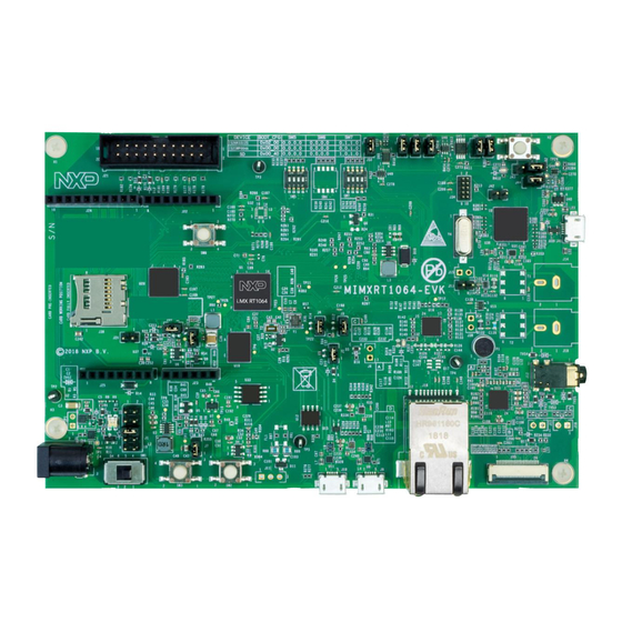
Block diagram. The document describes each block shown in Figure Figure 1. Block diagram The overview of the MIMXRT1060 EVK board is shown in Figure 2 Figure MIMXRT1060/1064 Evaluation Kit Board Hardware User's Guide, Rev. 0, 06/2020 User's Guide 5 / 19... - Page 6 NXP Semiconductors Specifications Figure 2. Overview of the MIMXRT1060 EVK board (Front side) MIMXRT1060/1064 Evaluation Kit Board Hardware User's Guide, Rev. 0, 06/2020 User's Guide 6 / 19...
-
Page 7: I.mx Rt1060/1064 Processor
The device has four boot modes (one is reserved for NXP use). The boot mode is selected based on the binary value stored in the internal BOOT_MODE register. Switch (SW7-3 and SW7-4) is used to select the boot mode on the MIMXRT1060/1064 EVK board. Table 2. Boot mode pin settings... -
Page 8: Power Tree
2.3 Power tree A DC 5 V external power supply is used to supply the MIMXRT1060/1064 EVK board at J2, and a slide switch SW1 is used to turn the Power ON/OFF. J41 and J9 is used to supply the EVK board. - Page 9 Specifications Figure 4. Power tree The power control logic of the MIMXRT1060/1064 EVK board is shown in the Figure • SNVS is powered first and then PMIC_REQ_ON is switched on to enable external DC/DC to power up other power domains.
- Page 10 Power for DCDC DCDC_IN VDD_SNVS_IN Power for SNVS and USB_OTG1_VBUS Power for USB VBUS USB_OTG2_VBUS Power for 12-bit ADC VDDA_ADC Table continues on the next page... MIMXRT1060/1064 Evaluation Kit Board Hardware User's Guide, Rev. 0, 06/2020 User's Guide 10 / 19...
-
Page 11: Sdram Memory
2.7 QSPI flash A 64 Mbit QSPI flash is used on the MIMXRT1060/1064 EVK board. If the developer wants to boot from the QSPI flash, the boot device switch (SW7) settings should be: OFF, OFF, ON, OFF, as shown in Table 3. -
Page 12: Ethernet Connector
USB connection. For the MIMXRT1060/1064 EVK board, J41 is the connector between the USB host and the RT1060/1064. To update the Open SDA firmaware, press the SW8 and Power on the board. There is a disk named "MAINTENANCE". Drag/drop the new firmware to the "MAINTENANCE"... -
Page 13: Arduino Expansion Port
Arduino interface. Table 7. Arduino Interface pin definitions UART_RX/D0 A0/ADC0 UART_TX/D1 A1/ADC1 D2/INT0 A2/ADC2 D3/INT1/PWM/OC2B A3/ADC3 D4/T0/XCK A4/ADC4/SDA D5/TI/PWM A5/ADC5/SCL D6/AIN0/PWM/OC0A D7/AIN1/PWM MIMXRT1060/1064 Evaluation Kit Board Hardware User's Guide, Rev. 0, 06/2020 User's Guide 13 / 19... -
Page 14: Camera Module Connector
2.15.1 Power switch SW1 is a slide switch to control the power of the MIMXRT1060/1064 EVK board when the power supply is from J2. • Sliding the switch to the ON position connects the 5 V power supply to the evaluation board main power system. -
Page 15: Sensor
480*3(RGB)*272. This module contains two FPC cables. The LCD interface is connected to J8 (A1-A40) and the CPT interface can be connected to J8 (B1-B6). You can purchase LCD modules from www.nxp.com. MIMXRT1060/1064 Evaluation Kit Board Hardware User's Guide, Rev. 0, 06/2020 User's Guide... -
Page 16: Chapter 3 Pcb Information
NXP Semiconductors Chapter 3 PCB information The MIMXRT1060/1064 EVK board is uses the standard 4-layer technology. The material used is FR-4. The PCB stack-up information is shown in Table Table 8. Board stack-up information Layer Description Copper(Oz) Dielectric Thickness(mil) Signal —... -
Page 17: Chapter 4 Evk Design Files
NXP Semiconductors Chapter 4 EVK design files You can download, the schematics, layout files, and gerber files (including Silkscreen) from nxp.com/MIMXRT1060-EVK. MIMXRT1060/1064 Evaluation Kit Board Hardware User's Guide, Rev. 0, 06/2020 User's Guide 17 / 19... -
Page 18: Chapter 5 Evk Contents
USB cable (Micro-B to Standard-A). Camera CA111C based on MT9M114. NOTE Power adapter, micro-SD card, and LCD module are not standard parts of the evaluation kit. MIMXRT1060/1064 Evaluation Kit Board Hardware User's Guide, Rev. 0, 06/2020 User's Guide 18 / 19... - Page 19 How To Reach Us Information in this document is provided solely to enable system and software implementers to use NXP products. There are no express or implied copyright licenses granted hereunder to Home Page: design or fabricate any integrated circuits based on the information in this document. NXP nxp.com reserves the right to make changes without further notice to any products herein.
Need help?
Do you have a question about the MIMXRT1060 and is the answer not in the manual?
Questions and answers