NXP Semiconductors MIMXRT1050 Hardware User's Manual
Evkb board
Hide thumbs
Also See for MIMXRT1050:
- Hardware user's manual (19 pages) ,
- Development manual (22 pages)

Subscribe to Our Youtube Channel
Related Manuals for NXP Semiconductors MIMXRT1050


Summary of Contents for NXP Semiconductors MIMXRT1050
- Page 1 NXP Semiconductors Document identifier: MIXRT1050EVKBHUG User's Guide Rev. 1, 11/2020 MIMXRT1050 EVKB Board Hardware User’s Guide...
-
Page 2: Table Of Contents
2.17 User interface LED indicator....................13 2.18 LCD interface.........................13 Chapter 3 PCB information.................. 14 Chapter 4 EVKB design files................15 Chapter 5 Contents of the Evaluation kit............. 16 Chapter 6 Revision history...................17 MIMXRT1050 EVKB Board Hardware User’s Guide, Rev. 1, 11/2020 User's Guide 2 / 18... -
Page 3: Chapter 1 Introduction
CAN Bus Connector User Interface Button ON/OFF, POR Reset, Reset, USER Button Led Indicator Power Status, Reset, OpenSDA, USER LED Table continues on the next page... MIMXRT1050 EVKB Board Hardware User’s Guide, Rev. 1, 11/2020 User's Guide 3 / 18... -
Page 4: Imxrt1050 Evkb Contents
2. Change C88 to 2.2 uf/35 V or 1.0 uf/35 V to ensure the back light control circuits working normally. This change is only for Rev A, A1 and B, but not for Rev B1. For details, see Figure Figure 1. EVKB board revision history MIMXRT1050 EVKB Board Hardware User’s Guide, Rev. 1, 11/2020 User's Guide 4 / 18... -
Page 5: Chapter 2 Specifications
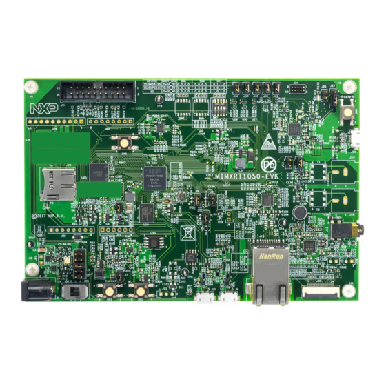
EVKB board, as shown in Figure 2, will be discussed. Figure 2. Block diagram The overview of the IMXRT1050 EVKB board is as shown in Figure 3 Figure MIMXRT1050 EVKB Board Hardware User’s Guide, Rev. 1, 11/2020 User's Guide 5 / 18... -
Page 6: I.mx Rt1050 Processor
CPU performance and best real-time response. The i.MX RT1050 provides various memory interfaces, including SDRAM, Raw NAND FLASH, NOR FLASH, SD/eMMC, Quad SPI, HyperBus and a wide range of other interfaces for connecting MIMXRT1050 EVKB Board Hardware User’s Guide, Rev. 1, 11/2020 User's Guide... -
Page 7: Boot Mode Configurations
Power ON/OFF. J28 and J9 can also be used to supply the EVKB Board. Different power supply need to configure different Jumper setting of J1. Table 4 describes the details. Table 4. Jumper settings of power supply Power supply J1 settings Table continues on the next page... MIMXRT1050 EVKB Board Hardware User’s Guide, Rev. 1, 11/2020 User's Guide 7 / 18... - Page 8 • ON/OFF button is used to switch ON/OFF PMIC_REQ_ON to control power modes. • The RESET button and WDOG output are used to reset the system power. MIMXRT1050 EVKB Board Hardware User’s Guide, Rev. 1, 11/2020 User's Guide 8 / 18...
- Page 9 IO supply for GPIO in EMC bank (3.3 V mode) NVCC_EMC 1.65 1.95 IO supply for GPIO in EMC bank (1.8 V mode) NVCC_GPIO IO power for GPIO MIMXRT1050 EVKB Board Hardware User’s Guide, Rev. 1, 11/2020 User's Guide 9 / 18...
-
Page 10: Sdram Memory
2. Weld 0 Ω resistors: R153 to R158. 2.8 Ethernet connector There is one Ethernet Mac controller in the MIMXRT1050 processor. The Ethernet subsystem of the IMXRT1050 EVKB board is provided by the KSZ8081RNB 10/100M Ethernet Transceiver (U16) and a RJ45 (J19) with integrated Magnetic. -
Page 11: Jtag Connector
J22 to J25 is defined as Arduino interface. Table 6 describes the pin definitions of Arduino interface. Table 6. Arduino interface pin definitions UART_RX/D0 A0/ADC0 D8/CLKO/ICP1 Table continues on the next page... MIMXRT1050 EVKB Board Hardware User’s Guide, Rev. 1, 11/2020 User's Guide 11 / 18... -
Page 12: Camera Module Connector
ON. In ON mode, a short pressing generates an interrupt (intended to be a software- controllable(power-down). An approximate 5 seconds or more pressing causes a forced OFF. Both boot mode inputs can be disconnected. MIMXRT1050 EVKB Board Hardware User’s Guide, Rev. 1, 11/2020 User's Guide 12 / 18... -
Page 13: Sensor
At the same time, you need to change C88 to 2.2uf/35V or 1.0uf/35V to ensure the back light control circuits working normally. This change is only for Rev A, A1 and B, not required for Rev B1. MIMXRT1050 EVKB Board Hardware User’s Guide, Rev. 1, 11/2020 User's Guide... -
Page 14: Chapter 3 Pcb Information
Table 7. Board stack-up information Layer Description Copper (Oz) Dielectric thickness(mil) Signal — Dielectric — — Dielectric — Power — Dielectric — Signal — MIMXRT1050 EVKB Board Hardware User’s Guide, Rev. 1, 11/2020 User's Guide 14 / 18... -
Page 15: Chapter 4 Evkb Design Files
NXP Semiconductors Chapter 4 EVKB design files The schematics, layout files, and gerber files (including Silkscreen) can be downloaded from MIMXRT1050-EVK. MIMXRT1050 EVKB Board Hardware User’s Guide, Rev. 1, 11/2020 User's Guide 15 / 18... -
Page 16: Chapter 5 Contents Of The Evaluation Kit
USB cable USB cable (Micro-B to Standard-A) NOTE Power adaptor, Micro SD Card, LCD Module and Camera Module are not standard parts of the Evaluation Kit. MIMXRT1050 EVKB Board Hardware User’s Guide, Rev. 1, 11/2020 User's Guide 16 / 18... -
Page 17: Chapter 6 Revision History
Table 9. Revision history Revision number Date Substantive changes 04/2018 Initial release 11/2020 Updated Figure 1 MIMXRT1050 EVKB Board Hardware User’s Guide, Rev. 1, 11/2020 User's Guide 17 / 18... - Page 18 Right to make changes - NXP Semiconductors reserves the right to make changes to information published in this document, including without limitation specifications and product descriptions, at any time and without notice. This document supersedes and replaces all information supplied prior to the publication hereof.
Need help?
Do you have a question about the MIMXRT1050 and is the answer not in the manual?
Questions and answers