NXP Semiconductors MIMXRT1050 Hardware User's Manual
Evk board hardware
Hide thumbs
Also See for MIMXRT1050:
- Hardware user's manual (18 pages) ,
- Development manual (22 pages)
Table of Contents
Advertisement
Quick Links
NXP Semiconductors
User's Guide
MIMXRT1050 EVK Board Hardware User's
Guide
1. Introduction
This document is a Hardware User's Guide for the
MIMXRT1050 Evaluation Kit (EVK) based on the NXP
Semiconductor i.MX RT1050 Processor. This board is fully
supported by NXP Semiconductor. This manual includes
system setup and debugging, and provides detailed
information on the overall design and usage of the EVK board
from a hardware systems perspective.
1.1. Board overview
This EVK board is a platform designed to showcase the most
commonly used features of the i.MX RT1050 Processor in a
small, low cost package. The MIMXRT1050 EVK board is an
entry level development board, which gives the developer the
option of becoming familiar with the processor before
investing a large amount or resources in more specific
designs.
© 2018 NXP B.V.
Document Number: MIMXRT1050EVKHUG
1.
Introduction ........................................................................ 1
Board overview ....................................................... 1
MIMXRT1050 EVK Contents ................................ 3
MIMXRT1050 EVK Board revision history ........... 3
2.
Specifications ..................................................................... 4
i.MX RT1050 Processor ......................................... 6
Boot Mode Configurations ...................................... 7
Power Tree .............................................................. 7
SDRAM memory .................................................. 10
SD Card Slot ......................................................... 10
Hyper Flash ........................................................... 11
QSPI Flash ............................................................ 11
Ethernet Connector ............................................... 11
USB PHY Connector ............................................ 11
Audio input / output Connector ............................. 12
OpenSDA circuit (DAP-Link) .............................. 12
JTAG Connector ................................................... 12
Arduino Expansion Port ........................................ 13
Camera Module Connector ................................... 14
User Interface Switch ............................................ 14
Sensor ................................................................... 15
User Interface LED Indicator ................................ 15
LCD Interface ....................................................... 15
3.
PCB Information .............................................................. 16
4.
EVK Design Files ............................................................ 16
5.
Contents of the Evaluation Kit ......................................... 16
6.
Revision history ............................................................... 17
Rev. 2 , 03/2018
Contents
Advertisement
Table of Contents

Subscribe to Our Youtube Channel
Related Manuals for NXP Semiconductors MIMXRT1050


Summary of Contents for NXP Semiconductors MIMXRT1050
-
Page 1: Table Of Contents
Camera Module Connector ........14 commonly used features of the i.MX RT1050 Processor in a User Interface Switch ..........14 small, low cost package. The MIMXRT1050 EVK board is an Sensor ..............15 User Interface LED Indicator ........ 15 entry level development board, which gives the developer the LCD Interface ............ - Page 2 User Interface Button ON/OFF, POR Reset, Reset, USER Button Led Indicator Power Status, Reset, OpenSDA, USER LED Expansion Port Arduino Interface 3.937-inch x 5.9055-inch (10cm x 15cm), 4-layer board MIMXRT1050 EVK Board Hardware User’s Guide, User's Guide, Rev. 2, 03/2018 NXP Semiconductors...
-
Page 3: Mimxrt1050 Evk Contents
• EVK Rev A3/4/5:Mass Product. NOTE EVK Rev A, Rev A1/2/3/4/5 Boards are based on A0 silicon. • EVKB: Mass Product. NOTE EVKB Boards are based on A1 silicon. MIMXRT1050 EVK Board Hardware User’s Guide, User's Guide, Rev. 2, 03/2018 NXP Semiconductors... -
Page 4: Specifications
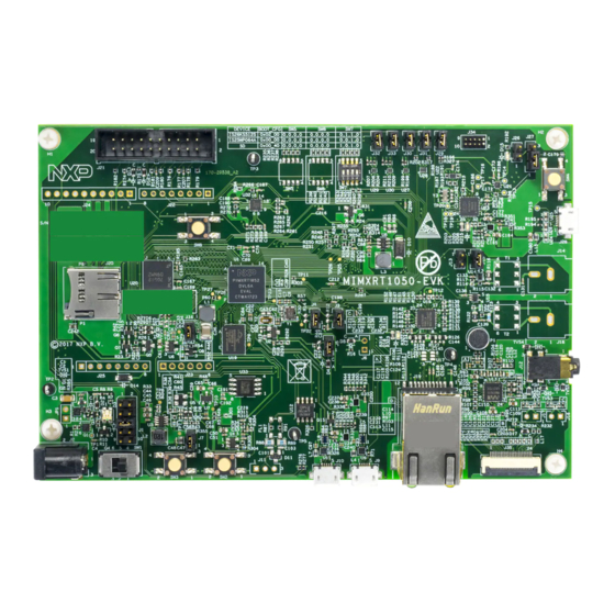
EVK Board, and is organized to discuss each block in the following block diagram of the EVK board. Figure 1. Block diagram The overview of the MIMXRT1050 EVK Board is shown in Figure 1 & Figure MIMXRT1050 EVK Board Hardware User’s Guide, User's Guide, Rev. 2, 03/2018 NXP Semiconductors... - Page 5 Specifications Figure 2. Overview of the MIMXRT1050 EVK Board (Front side) MIMXRT1050 EVK Board Hardware User’s Guide, User's Guide, Rev. 2, 03/2018 NXP Semiconductors...
-
Page 6: I.mx Rt1050 Processor
WLAN, Bluetooth™, GPS, camera sensors, and multiple displays. The more detail information about i.MX RT1050 can be found in the Datasheet and Reference manual. MIMXRT1050 EVK Board Hardware User’s Guide, User's Guide, Rev. 2, 03/2018 NXP Semiconductors... -
Page 7: Boot Mode Configurations
2.3. Power Tree A DC 5V external power supply is used to supply the MIMXRT1050 EVK Board at J2, and a slide switch SW1 is used to turn the Power ON/OFF. J28 and J9 also can be used to supply the EVK Board. - Page 8 The power tree is shown in the following figure. Figure 4. Power Tree The power control logic of the MIMXRT1050 EVK board is shown in the following figure: For A0 silicon: • It will power up SNVS and DCDC_IN together firstly, then PMIC_REQ_ON will be switched on to enable external DC/DC to power up other power domains.
- Page 9 Figure 5. Power Control Diagram NOTE Power Control Diagram described in MIMXRT1050 EVK Board is true for A0 silicon For A1 silicon, DCDC_IN is expected to be powered with other domains together. In the other word, for A0 silicon the DCDC_IN is powered with LDO (Path 1). And for A1 silicon, it is expected to be powered with DC/DC (Path 2).
-
Page 10: Sdram Memory
2.5. SD Card Slot There is a SD card slot(J20) on the MIMXRT1050 EVK Board.J20 is the Micro SD slot for USDHC1 interface. If the developer wants to boot from the SD Card, the boot device switch (SW7) settings should be: ON, OFF, ON, OFF, as shown in Table 3. -
Page 11: Hyper Flash
Table3. 2.7. QSPI Flash A 64Mbit QSPI Flash is used on the MIMXRT1050 EVK Board. If the developer wants to boot from the QSPI Flash, the boot device switch(SW7) settings should be: OFF, OFF, ON, OFF, as shown in Table3. -
Page 12: Audio Input / Output Connector
COM communication interface while allowing code debugging via CMSIS-DAP with just single USB connection. For the MIMXRT1050 EVK Board, J28 is the connector between the USB host and the target processor. Jumper to serial downloader mode to use stable DAP-Link debugger function. If developer wants to make OpenSDA going to the bootloader mode, J27 should jumper to 1-2, and press SW4 when power on. -
Page 13: Arduino Expansion Port
J22 – J25 (unpopulated) is defined as Arduino Interface. The pin definitions of Arduino Interface are shown in Table Table 6. Arduino Interface pin definitions UART_RX/D0 A0/ADC0 UART_TX/D1 A1/ADC1 D2/INT0 A2/ADC2 D3/INT1/PWM/OC2B A3/ADC3 D4/T0/XCK A4/ADC4/SDA D5/TI/PWM A5/ADC5/SCL D6/AIN0/PWM/OC0A D7/AIN1/PWM MIMXRT1050 EVK Board Hardware User’s Guide, User's Guide, Rev. 2, 03/2018 NXP Semiconductors... -
Page 14: Camera Module Connector
2.15.1. Power Switch SW1 is a slide switch to control the power of the MIMXRT1050 EVK Board when the power supply is from J2. The function of this switch is listed below: • Sliding the switch to the ON position connects the 5V power supply to the Evaluation board main power system. -
Page 15: Sensor
• Bus master interface to source frame buffer data for display refresh. • 8/16/18/24/32 bit LCD data bus support available depending on I/O mux options. • Programmable timing and parameters for DOTCLK LCD interfaces. MIMXRT1050 EVK Board Hardware User’s Guide, User's Guide, Rev. 2, 03/2018 NXP Semiconductors... -
Page 16: Pcb Information
FPC cables. The LCD interface can be connected to J8(A1-A40) and the CPT interface can be connected to J8(B1-B6). LCD modules can be purchased from the NXP website. 3. PCB Information The MIMXRT1050 EVK Board is made using standard 4-layer technology. The material used was FR- 4. The PCB stack-up information is shown in Table Table 7. -
Page 17: Revision History
9 summarizes the changes made to this document since the initial release. Table 9. Revision history Revision number Date Substantive changes 08/2017 Initial release 11/2017 References/links have been completed 03/2018 Add(Update) information for RT1050 silicon A1 MIMXRT1050 EVK Board Hardware User’s Guide, User's Guide, Rev. 2, 03/2018 NXP Semiconductors... - Page 18 Information in this document is provided solely to enable system and software implementers to use NXP products. There are no express or implied copyright licenses granted hereunder to design or fabricate any integrated circuits based on the information in this document. NXP reserves the right to make changes without further notice to any products herein.
- Page 19 Mouser Electronics Authorized Distributor Click to View Pricing, Inventory, Delivery & Lifecycle Information: MIMXRT1050-EVKB...
Need help?
Do you have a question about the MIMXRT1050 and is the answer not in the manual?
Questions and answers