
Subscribe to Our Youtube Channel
Related Manuals for Arbor Technology FPC-5211 Series


Summary of Contents for Arbor Technology FPC-5211 Series
- Page 1 FPC-5211 Series Intel / 13 Gen Core Fanless Edge AI ® Computer supporting Nvidia RTX-A2000 ® User’s Manual Version 1.0 P/N: 4016521100100P 2023.10...
- Page 2 This page is intentionally left blank. - 2 -...
- Page 3 Revision History Version Release Time Description 2023.10 Initial release - i -...
-
Page 4: Table Of Contents
Contents Contents Revision History ................i Contents ..................ii Preface.................... v Copyright Notice.................. v Declaration of Conformity..............v CE ....................v FCC Class A ................v RoHS ...................vi SVHC / REACH ................vi Important Safety Instructions .............vii Warning .....................viii Replacing Lithium Battery ..............viii Technical Support................viii Warranty ....................ix Chapter 1 - Introduction .............. -
Page 5: Contents
Contents 4.2. Wire DC-in Power Source ............51 4.2.1 Automation Mode ............. 51 4.2.2 Vehicle Application Mode ..........52 4.3 Wall Mounting ................53 Chapter 5 - BIOS ................55 5.1. Main ................... 58 5.2. Advanced ................... 59 5.2.1. CPU Configuration ............61 5.2.2. - Page 6 This page is intentionally left blank. - iv -...
-
Page 7: Preface
Preface Preface Copyright Notice All Rights Reserved. The information in this document is subject to change without prior notice in order to improve the reliability, design and function. It does not represent a commitment on the part of the manufacturer. Under no circumstances will the manufacturer be liable for any direct, indirect, special, incidental, or consequential damages arising from the use or inability to use the product or documentation, even if advised of the possibility of such... -
Page 8: Rohs
(PBDE) in electrical and electronic products. Member states of the EU are to enforce by 7/1/2006. ARBOR Technology Corp. hereby states that the listed products do not contain unintentional additions of lead, mercury, hex chrome, PBB or PBDB that exceed a maximum concentration value of 0.1% by weight or for cadmium exceed... -
Page 9: Important Safety Instructions
Preface Important Safety Instructions Read these safety instructions carefully Read all cautions and warnings on the equipment. Place this equipment on a reliable surface when installing. Dropping it or letting it fall may cause damage Make sure the correct voltage is connected to the equipment. For pluggable equipment, the socket outlet should be near the equipment and should be easily accessible. -
Page 10: Warning
Preface Warning The Box PC and its components contain very delicately Integrated Circuits (IC). To protect the Box PC and its components against damage caused by static electricity, you should always follow the precautions below when handling it: Disconnect your Box PC from the power source when you want to work on the inside. -
Page 11: Warranty
Preface Warranty This product is warranted to be in good working order for a period of one year from the date of purchase. Should this product fail to be in good working order at any time during this period, we will, at our option, replace or repair it at no additional charge except as set forth in the following terms. - Page 12 This page is intentionally left blank. - x -...
-
Page 13: Chapter 1 - Introduction
Chapter 1 Introduction Chapter 1 - Introduction - 1 -... -
Page 14: The Computer
Introduction 1.1. The Computer FPC-5211-M4 • Fanless design ( Embedded heat pipes cooling solution) • / 13 Gen Core i9/i7/i5/i3 Processor (Alder Lake-S/Raptor Lake-S) • Up to 60W GPU MXM module expansion • 4 x 802.3af (15.4W) Gigabit PoE ports •... -
Page 15: Specifications
Introduction 1.3. Specifications FPC-5211-M4 System Intel / 13 generation Core™ i9/i7/i5/i3 processor in ® LGA1700 socket ( Max 35W CPU) 2 x 262-pin DDR5 SO-DIMM sockets, supporting Memory 4800 MHz SDRAM up to 64GB (ECC/ Non-ECC) Chipset Intel R680E ® Graphics Integrated Intel HD Graphics 770... - Page 16 Introduction 1 x MXM3.1 TYPE A/B GPU Slot (PCIe Gen5 x16) MXM A2000 support 2 x mPCIe Slots interconnected with SIM card sockets for optional WiFi/BT/3G/LTE/ GPS (PCIex1+USB2.0, Full Size) Expansion Bus 1 x M.2 B key (2242/3052/2280) w/ (PCIex2+USB3.0+SATA) interconnected with SIM for 5G / LTE or for storage (either one) 1 x M.2 E key ( 2230) with PCIex1+USB2.0+CNVi) for Wireless Environmental...
- Page 17 Introduction OS Support Windows 10 IOT Enterprise 64-bit Linux ( Ubuntu 20.04 ) Ordering Information FPC-5211-M4 Edge AI GPU Computer Bare BOM, w/4x M12 PoEs FPC-5211-P6 System Intel / 13 generation Core™ i9/i7/i5/i3 processor in ® LGA1700 socket ( Max 35W CPU) 2 x 262-pin DDR5 SO-DIMM sockets, supporting Memory 4800 MHz SDRAM up to 64GB (ECC/ Non-ECC)
- Page 18 Introduction Audio Mic-in/Line-out 1 x MXM3.1 TYPE A/B GPU Slot (PCIe Gen5 x16) MXM A2000 support 2 x mPCIe Slots interconnected with SIM card sockets for optional WiFi/BT/3G/LTE/ GPS (PCIex1+USB2.0, Full Size) Expansion Bus 1 x M.2 B key (2242/3052/2280) w/ (PCIex2+USB3.0+SATA) interconnected with SIM for 5G / LTE or for storage (either one) 1 x M.2 E key (2230) with PCIex1+USB2.0+CNVi) for Wireless Environmental...
-
Page 19: Inside The Package
Upon opening the package, carefully inspect the contents. If any of the items is missing or appears damaged, contact your local dealer or distributor. The package should contain the following items: 1 x FPC-5211 Series Robust System 1 x User’s Manual 1.4.1. -
Page 20: Optional Configuration (Ctos* Kit)
Introduction 1.4.2. Optional Configuration (CTOS* Kit) Make the computer more tailored to your needs by selecting one or more components from the list below to be fabricated to the computer. MXM 3.1 Type A NVIDIA Quadro Embedded ® ® MXM-A2000-8G A2000_8GB GDDR6 60W TGP) MM-5C- DDR5-4800 8GB/16GB/32G SDRAM DIMM module... -
Page 21: Chapter 2 - System Overview
Chapter 2 System Overview Chapter 2 - System Overview - 9 -... -
Page 22: Dimensions
System Overview 2.1. Dimensions FPC-5211-M4 - 10 -... - Page 23 System Overview FPC-5211-P6 50.00 50.00 4.00 90.00 80.00 80.00 97.00 230.00 - 11 -...
-
Page 24: Take A Tour
System Overview 2.2. Take A Tour 2.2.1. FPC-5211-M4(FPC-5211-P6) Front View 2.2.2. FPC-5211-M4 Rear View - 12 -... -
Page 25: Fpc-5211-P6 Rear View
System Overview 2.2.3. FPC-5211-P6 Rear View 2.3. Driver Installation Notes The CPU module supports Windows 10 64-bit and Linux. To install the drivers, please go to our website at www.arbor-technology.com and download the driver pack from the product page. Then extract the down- loaded file and follow the sequence below to install the drivers: Chipset →... - Page 26 This page is intentionally left blank. - 14 -...
-
Page 27: Chapter 3 - System Configuration
Chapter 3 System Configuration Chapter 3 - System Configuration - 15 -... -
Page 28: Board Layout
Engine of the Computer 3.1. Board Layout Board Top ⑭ DGP1 ⑮ MMKey 1 ⑬ JBAT1 ⑫ JACCON2 ⑪ ⑩ JBAT1 ⑨ JACCON1 ⑧ JPSW1 ⑦ JPWRIN1 ⑤ GPU FAN3 ⑥ ① MXM1 Slot GPU FAN1 ④ GPU FAN2 ② CPU FAN1 ③... - Page 29 Engine of the Computer Board Bottom ⑯ JPWRIN2 MC1/MC2 MBKEY SYSFAN 1/2 ⑰ PWROUT 1-4 ⑱ SATA1-4 ⑲ USBCN1 MEKEY1 - 17 -...
- Page 30 Engine of the Computer Jumpers & Connectors Label Description ①④ Fan power connector GPU FAN1~2 ⑤ Fan power connector GPU FAN3 ②③ Fan power connector CPU FAN1 ⑥ MXM Expansion Slot MXM1 Slot ⑦ Power Input JPWRIN1 ⑧ Power Button JPSW1 ⑩⑪...
-
Page 31: Pinheaders And Connectors
Engine of the Computer 3.2. Pinheaders and Connectors 3.2.1 Main board ①④ GPU FAN1~2 Function: Fan Power Connector Connector Type: Onboard 4-pin header/ ① ④ pitch 2.54mm/ pitch 2.00mm Pin Assignment: Pin Description ① ④ 1 GND 2 +12V 3 PWM 4 Control ⑤... - Page 32 Engine of the Computer ⑥ MXM Expansion slot Function: External MXM slot Connector Type: MXM3.1 TYPE A/B GPU Slot Pin Assignment: The pin assignments conform to the industry standard ⑦ JPWRIN1 Function Power Input Connector Type: Onboard 4-Pin Terminal block Pin Assignment: Pin Description DCIN...
- Page 33 Engine of the Computer ⑨ JACCON1 Function Vehicle Acc Mode Selection Connector Type: Onboard 2-pin header Pin Assignment: Description Enable: 1-2 short (default) Disable: 1-2 open ⑫ JACCON2 Function ACC ON Signal Connector Type: Onboard 2-pin header Pin Assignment: Pin Description ACC_ON ⑬...
- Page 34 Engine of the Computer ⑭ DGP1 Function: Debug Port Connector Type: Onboard 10-pin header Pin Assignment: Pin Desc. Pin Desc. ESPI_CLK ESPI_CS0# ESPI_IO0 ESPI_RST# V3.3A ESPI_IO3 ESPI_IO2 V3.3S ESPI_IO1 ⑮ MMKEY1 Function: M.2 M-Key Connector Connector Type: M.2 75-pin M-Key connector for PCIe x4/SATA-III SSD storage, supporting 22x42 / 22x80 modules Pin Assignment: The pin assignments conform to the industry standard.
- Page 35 Engine of the Computer ⑰ PWROUT1~4 Function: SATA HDD Power Connector Connector Type: 2.54mm pitch 1x4-pin one-wall connector Pin Assignment: Description +12V ⑱ SATA1~4 Function: Serial ATA Connector Connector Type: On-board Stabdard 7-pin Serial ATA Connector Pin Assignment: Description ⑲ USBCN1 Function: USB2.0 Wafer...
- Page 36 Engine of the Computer ⑳ JPWRIN2 Function: VGA card power Connector Type: oboard 2.54mm pitch 4-pin wafer Pin Assignment: Desc. DCIN DCIN MC1/MC2 Function: PCI Express Mini-card Full socked Connector Type: Onboard 0.8mm pitch 52-pin edge card connector. Pin Assignment: MBKEY1 Function: M.2 B-Key socket...
- Page 37 Engine of the Computer MEKEY1 Function: M.2 E-Key socket (w/ CNVi+USB2.0) for optional Wi-Fi/BT Connector Type: M.2 E-Key 2230 Socket Pin Assignment: The pin assignments conform to the industry standard. - 25 -...
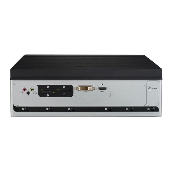
- Page 38 Engine of the Computer FPC-5211-M4(FPC-5211-P6) Front side Mic-in Power On/Off Button Line-out SIM card DVI-I Port HDMI Port sockets FPC-5211-M4 Rear side ⑱LED indicator ⑯2.5GbE/GbE LAN ⑮COM1/COM2 ⑭DI/DO-Isolated Ports ⑰Display Port ⑲Fan connector ⑦Ignition Switch ⑬Reset ⑧DC-IN button ⑨Ground ⑩PoE indicator ⑫COM3/COM4 USB 3.2 Ports ⑭HDD Tray...
- Page 39 Engine of the Computer ③ SIM Card socket Function: SIM Card Socket Connector Type: 6-pin SIM card socket Pin Assignment: Desc. Pin Desc C2 RST C5 GND C7 I/O ⑦ Ignition Switch Function: vehicle application Connector Type: 2-Pin Terminal block Pin Assignment: Desc.
- Page 40 Engine of the Computer ⑭ DIOCN1 Function: Isolated DIO Connector Type: 15-pin D-sub male connector Pin Assignment: Analog RGB DIOCN1 (DOWN) DIOCN1 (UP) NO. Desc. NO. Desc DOUT_00 DI_00 DOUT_01 DI_01 DOUT_02 DI_02 DOUT_03 DI_03 DOUT_04 DI_04 DOUT_05 DI_05 DOUT_06 DI_06 DOUT_07 DI_07...
- Page 41 Engine of the Computer ⑮ COM1, COM2 Function: RS-232/422/485 Selectable Serial Port Connector Type: 9-pin D-sub male connector Pin Assignment: Pin Desc. Pin Desc RS-232 COM_422 TX- COM_422 TX+ RS-422 COM_422 RX+ COM_422 RX- COM_485 D- RS-485 COM_485 D+ ⑲ FAN connector Function: Fan Connector...
- Page 42 Engine of the Computer ⑱ LED Indicator Statement Function: LED Indicator Pin Assignment: Desc. LED Color Function STANDBY This LED lights Red when in standyby mode Power Status Green This LED lights Red when power is on (PWR) This LED lights Red when ACC power is on HDD_0 Green This LED lights when the HDD/SSD was detected in HDD0...
- Page 43 Engine of the Computer ⑩ PoE Indicator Statement Function: PoE LED Indicator Pin Assignment: Location Silk Function LED Color 10/100M Steady Green Upper LED LINK Steady Orange Down LED Active Flashing Yellow - 31 -...
- Page 44 This page is intentionally left blank. - 32 -...
-
Page 45: Chapter 4 - Installation And Maintenance
Chapter 4 Installation and Maintenance Chapter 4 - Installation and Maintenance - 33 -... -
Page 46: Install Hardware
Installation & Maintenance 4.1. Install Hardware The FPC-5211 Series is constructed based on modular design to make it easy for users to add hardware or to maintain the computer. The following sections will guide you to the simple hardware installations for the computer. - Page 47 Installation & Maintenance Carefully lift the top cover and then completely part the top and slide the side cover from the computer. The inside of the computer comes to view. - 35 -...
- Page 48 Installation & Maintenance 4.1.1.3. Remove Bottom Cover Loosen and remove the 2 screws at the bottom as shown below. 3. Carefully lift the bottom over and then completely part the side cover from the computer. The inside of the computer comes to view. - 36 -...
-
Page 49: Install Cpu
Installation & Maintenance 4.1.2. Install CPU Remove the top and side cover from the computer as described in 4.1.1.3. on page Remove Bottom Cover Locate the CPU socket on the main board The processor socket comes with a lever to secure the processor. Please refer to the pictures step by step as below and note that the cover of the socket must always be installed during transportation to avoid damage to the socket. -
Page 50: Install/Uninstall Memory Modules
The main board has two memory module (DIMM) sockets. Increase memory capacity to make programs run faster on the system. The memory module for the FPC-5211 Series’ SO-DIMM sockets should be a 262-pin DDR5 with a “key notch” off the centre among the pins, which enables the memory module for particular applications. - Page 51 Installation & Maintenance Align the notch on the memory module with the key in the module socket. - 39 -...
- Page 52 Installation & Maintenance Pluh the module into place. Once the memory module is fully inserted into the socket, press down on the top edge of the device to latch it into place. This way it’s flat to the laptop’s bottom. The carrier should snap into place with latches.
- Page 53 Installation & Maintenance To uninstall a DDR5 memory module: Pull back both latches from the SO-DIMM socket. The DDR5 memory module will be auto-released from the socket. Remove the memory module. Restore the top cover to the computer. - 41 -...
-
Page 54: Installing M.2 Storage Module
Installation & Maintenance 4.1.4. Installing M.2 Storage Module The computer has a M.2 M-Key socket for NvME SSD storage. This section will use a 22 x 80 form factor as the installation example. Remove the top cover from the computer as described in 4.1.1.2. -
Page 55: Install Wi-Fi Module
Installation & Maintenance 3. Insert and fasten the screw into the standoff. 4.1.5. Install Wi-Fi Module Remove the back cover from the computer as described in Section 4.1.1.3. Remove Bottom Cover on page Locate the M.2 E-Key socket for wireless module. Prepare the Wi-Fi module kit. - Page 56 Installation & Maintenance Two MHF connectors, one is “MAIN” (marked 2), the other is “AUX” (marked 1). Have the RF antenna. The antenna has an SMA connector on one end and an MHF connector on the other. SMA connector MHF connector Connect the RF antenna’s MHF connector to the Wi-Fi module’s main connector marked 0.
- Page 57 Installation & Maintenance Connect the RF antenna’s MHF connector to the Wi-Fi module’s main connector (marked 2) Connect the secondary RF antenna’s MHF connector to the Wi-Fi module’s secondary connector (marked 1) Plug the Wi-Fi module to the socket’s connector by a slanted angle. Fully plug the module, and note the notch on the wireless module should meet the break of the connector.
- Page 58 Installation & Maintenance make an antenna hole. Keep the plastic plug for any possible restoration in the future. From the other end of the RF antenna, which is an SMA connector, remove the washer and the nut. Note the SMA connector has the form of a threaded bolt, with one flat side.
- Page 59 Installation & Maintenance 12. Have the external antenna(s). Screw and tightly fasten the antenna(s) to the SMA connector. 13. After completing the required hardware installation, assemble the computer by performing the proceeding steps in reverse order. - 47 -...
-
Page 60: Install Internal Sata Storage Device
Installation & Maintenance 4.1.5. Install Internal SATA Storage Device The computer supports two 2.5” SATA storage devices to work inside the computer for RAID. The following will guide you to install two SATA HDD/SSD. Find the HDD/SSD brackets. Loosen the screws as marked in the illustration below and take the bracket out. -
Page 61: Install Mxm3.1 Type A/B Gpu Cards
Installation & Maintenance If you are going to install the 2nd HDD/SSD storage device, slide the storage device into the bracket and fix it in place in the same way. Restore the HDD/SSD bracket to the computer. 4.1.6. Install MXM3.1 TYPE A/B GPU Cards To install a PCI or PCI Express card: Remove the top cover from the computer as described in section 4.1.1.2. - Page 62 Installation & Maintenance a. Align the graphics card notch with the slot on the board and push the graphics card into the slot until firmly inserted. b. Then tighten the screws to secure GPU card. Remove liner papers on the top cover. Restore the top cover to the computer.
-
Page 63: Wire Dc-In Power Source
Installation & Maintenance 4.2. Wire DC-in Power Source 4.2.1 Automation Mode Follow the instructions below for connecting the computer to a DC-input power source. Warning Only trained and qualified personnel are allowed to install or replace this equipment. Before wiring, make sure the power source is disconnected. Find the terminal block in the accessory box. -
Page 64: Vehicle Application Mode
Installation & Maintenance 4.2.2 Vehicle Application Mode Follow the instructions below for connecting the computer to a vehicle power source. Make sure JACCON1 jumper is open for vehicle power mode. (Refer to on page 3.2. Pinheaders and Connectors For vehicle application, DC power Input wiring pin configuration is as below. -
Page 65: Wall Mounting
Installation & Maintenance 4.3 Wall Mounting Prepare the wall mount kit and a screwdriver for wall mounting. Follow the instructions below: 1. Align the screw holes of the wall mount bracket with the ones of the main unit. Using the M3 screws included in the wall mount kit, fasten the wall mount bracket to the computer's case. - Page 66 This page is intentionally left blank. - 54 -...
-
Page 67: Chapter 5 - Bios
Chapter 5 BIOS Chapter 5 - BIOS - 55 -... - Page 68 BIOS The BIOS Setup utility for the FPC-5211 Series is featured by American Megatrends Inc to configure the system settings stored in the system’s BIOS ROM. The BIOS is activated once the computer powers on. When the computer is off, the battery on the main board supplies power to BIOS RAM.
- Page 69 BIOS Key Commands The BIOS Setup utility relies on a keyboard to receive user’s instructions. Hit the following keys to navigate within the utility and use the utility. Keystroke Function ← → Moves left/right between the top menus. ↓ ↑ Moves up/down between highlight items.
-
Page 70: Main
BIOS 5.1. Main The Main menu features the settings of System Date and System Time and displays some BIOS info. The featured settings are: Setting Description Set the system date. Use Tab to switch between Data elements. Note that the ‘Day’ automatically changes when you set the date. ►... -
Page 71: Advanced
BIOS 5.2. Advanced The featured settings and submenus are: Setting Description CPU Configuration 5.2.1. CPU Configuration on page Power & Performance 5.2.2. Power & Performance on page Trusted Computing 5.2.3. Trusted Computing on page 64 ACPI Settings 5.2.4. ACPI Settings on page 65 SMART Settings 5.2.5. - Page 72 BIOS AMI Graphic Outut protocol 5.2.11. AMI Graphic Output Protocol Policy on policy page 72 USB Configuration 5.2.12. USB Configuration on page 73 Network Stack Configuration 5.2.13. Network Stack Configuration on page 75 NVMe Configuration 5.2.14. NVME Configuration on page 76 - 60 -...
-
Page 73: Cpu Configuration
BIOS 5.2.1. CPU Configuration The features settings are: Setting Description Performance-core Information Display the P-core information When enabled, a VMM can utilize the additional hardware Intel (VMX) Virtualization capabilities provided by Vanderpool Technology. Technology Options: Enabled (default) or Disabled ► Number of cores to enable in each processor package. -
Page 74: Power & Performance
BIOS 5.2.2. Power & Performance The features settings are: Setting Description CPU - Power Management Control Options Control CPU Power Management: ► Options: Boot performance mode: Max Battery, Max Non-Turbo performance, Turbo performance(Default) Control CPU Power Management: CPU - Power management Intel(R) SpeedStep(tm): Control ►... - Page 75 BIOS RC6(Render Standby): Check to enable render standby Options: Disabled / Enabled(Default) ► Maximum GT frequency: Maxium GT frequency limited by the user. Choose between 300MHz and 1450MHz. GT - Power Management Options: Default Max Frequency(Default), ► Control 100Mhz~1200Mhz Disable Turbo GT Frequency: Enabled/Disabled GT Frequency.
-
Page 76: Trusted Computing
BIOS 5.2.3. Trusted Computing The features settings are: Setting Description Security Device Support Enable (default) or Disable BIOS support for security device. Schedule an Operation for the security Device. Your computer will reboot during restart in order to change State Pending operation of Security Device. -
Page 77: Acpi Settings
BIOS 5.2.4. ACPI Settings The features settings are: Setting Description Enables (default) or Disables System ability to Enable Hibernation Hibernate (OS/S4 Sleep State). This option may be not effective with some OS. Select ACPI sleep state the system will enter when the SUSPEND button is pressed. -
Page 78: Smart Settings
BIOS 5.2.5. Smart Settings Setting Description Run Smart Self Test on all HDDs during POST. Smart Settings Options: Enabled(default) or Disabled - 66 -... -
Page 79: F81966 Super Io Configuration
BIOS 5.2.6. F81966 Super IO Configuration Super IO Chip F81866 Settings Setting Description Serial Port Configuration Enable (default) or Disable Serial Port (COM). Serial Port 1-2 Select RS-232 (default), RS-422, RS-485, or RS-485 Configuration Termination Resistor - 67 -... -
Page 80: Hardware Monitor
BIOS 5.2.7. Hardware Monitor The features settings are: Setting Description CPU Smart Fan function settings. Fan mode selection: SmartFan Function ► Options: Auto - Dupty Cycle(default) or Manial - Dupty Cycle GPU Smart Fan function settings. Update CPU fan speed while system reboot: Options: Disabled(default) or Enabled CPU ►... -
Page 81: F81216Sec Super Io Configuration
BIOS 5.2.8 F81216SEC Super IO Configuration Setting Description Select an optimal setting for Super IO device. ► Options for Serial Port 3: Serial Port= Disabled or Enabled(default); Mode Select: RS-232/ RS-422/ RS-485/ RS-422 Termination Resistor/ RS-485 Termination Resistor Change Settings ►... -
Page 82: S5 Rtc Wake Settings
BIOS 5.2.9. S5 RTC Wake Settings The features settings are: Setting Description Enable or Disable (default) system wake on alarm event. ► Options available are: Disabled (default): Wake System Fixed Time: System will wake on the hr::min::sec specifiedc. from S5 DynamicTime: If selected, you need to set Wake up minute increase from 1 - 5. -
Page 83: Serial Port Console Redirection
BIOS 5.2.10. Serial Port Console Redirection The features settings are: Setting Description Use this item to enable or disable Console Redirection. The optional settings: [Disabled]; [Enabled]. Console Redirection When set as [Enabled], user can make further settings in the following items: Out-of-Band Mgmt Port Console Redirection... -
Page 84: Ami Graphic Output Protocol Policy
BIOS 5.2.11. AMI Graphic Output Protocol Policy Access this submenu to select output interface. The features settings are: Setting Description Select Output Interface Output select - 72 -... -
Page 85: Usb Configuration
BIOS 5.2.12. USB Configuration The features settings are: Setting Description Enables/disables legacy USB support. Options available are Enabled (default), Disabled and ► Auto. Legacy USB Support Select Auto to disable legacy support if no USB device ► are connected. Select Disabled to keep USB devices available only for ►... - Page 86 BIOS Use this item to set the time-out value for control, bulk, and USB Transfer time- interrupt transfers. Options: 1 sec, 5 sec, 10 sec, 20 sec ► (default). Use this item to set USB mass storage device start unit command time-out.
-
Page 87: Network Stack Configuration
BIOS 5.2.13. Network Stack Configuration The features settings are: Setting Description Network Stack ► Options are: [Enable] / [Disable] (default) - 75 -... -
Page 88: Nvme Configuration
BIOS 5.2.14. NVME Configuration Access this submenu to view the NVMe controller and driver information. - 76 -... -
Page 89: Chipset
BIOS 5.3. Chipset The Chipset menu controls the system’s chipset. The features settings are: Setting Description System Agent (SA) Configuration Access this submenu to view the memory Memory Configuration configuration. - 77 -... - Page 90 BIOS DP 1 Display: Select IGFX or MXM grapghics device ► Options: IGFX DP(default) or MXM DP. DP 2 Display: Select IGFX or MXM grapghics device Options: IGFX DP(default) or MXM DP. ► Primary Display: Select which of IGFX/PEG/ PCI Graphics devics should be Primary Display or Graphics Configuration select HG for Hybrid Gfx.
-
Page 91: Sata Configuration
BIOS 5.3.1. SATA Configuration The features settings are: Setting Description Enables (default) / Disables SATA device(s). SATA Controller(s) SATA device information. Serial ATA Port 0~6 Enables (default) / Disables the SATA port. *Available SATA ports depend on your model. Enables / Disables(default) SATA Port Device to sleep. SATA Port 0~6 Devslp - 79 -... -
Page 92: Security
BIOS 5.4. Security The features settings are: Setting Description If ONLY the Administrator’s password is set, then this only limits access to Setup and is only asked for when entering Setup. If ONLY the User’s password is set, then this is a power on password and must be entered to boot or enter Setup. - Page 93 BIOS Secure Boot Press [Enter] to make customized secure settings: ► Options are: [Disabled] or [Enabled] Secure Boot Mode Secure Boot fearuew is Active if Secure Boot is Secure Boot menu Enabled: ► Options are: [Custom] or [Standard] Key Management ►...
-
Page 94: Boot
BIOS 5.5. Boot The features settings are: Setting Description Set how long to wait for the prompt to show for entering BIOS Setup. Setup Prompt Timeout ► The default setting is 1 (sec). Set it to 65535 to wait indefinitely. ►... - Page 95 BIOS Power Delay Function Power Delay Function Set the system support power delay function. ► Options: Enable (default): Support power delay function. Disable: Power on/off manually operated. Power on delay Select the time which the system will power on. Options: Manually Operator (default), 04 Seconds, ►...
-
Page 96: Save & Exit
BIOS 5.6. Save & Exit The features settings are: Setting Description Save Changes Saves the changes and quits the BIOS Setup utility. and Exit Restores all settings to defaults. Restore Defaults ► This is a command to launch an action from the BIOS Setup utility. -
Page 97: Mebx
BIOS 5.7. MEBx The Intel MEBX provides the ability to change and/or collect the system hardware configuration. - 85 -...
Need help?
Do you have a question about the FPC-5211 Series and is the answer not in the manual?
Questions and answers