Table of Contents
Advertisement
Quick Links
®
NETWORK SERVICES
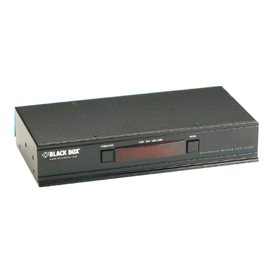
ServSwitch Wizard VGA (USB)
Control up to four VGA video-equipped computer
systems and share peripherals among them.
KV3004A supports one video head per channel, KV3204A supports two,
KV3304A supports three, and KV3404A supports four.
Order toll-free in the U.S.: Call 877-877-BBOX (outside U.S. call 724-746-5500)
Customer
FREE technical support 24 hours a day, 7 days a week: Call 724-746-5500 or fax 724-746-0746
Support
Mailing address: Black Box Corporation, 1000 Park Drive, Lawrence, PA 15055-1018
Information
Web site: www.blackbox.com • E-mail: info@blackbox.com
Download from Www.Somanuals.com. All Manuals Search And Download.
®
July 2010
KV3004A
KV3204A
KV3304A
KV3404A
Advertisement
Table of Contents

Related Manuals for Black Box ServSwitch KV3004A


Summary of Contents for Black Box ServSwitch KV3004A
- Page 1 Customer FREE technical support 24 hours a day, 7 days a week: Call 724-746-5500 or fax 724-746-0746 Support Mailing address: Black Box Corporation, 1000 Park Drive, Lawrence, PA 15055-1018 Information Web site: www.blackbox.com • E-mail: info@blackbox.com Download from Www.Somanuals.com. All Manuals Search And Download.
- Page 2 ServSwitch Wizard VGA (USB) Trademarks Used in this Manual Black Box and the Double Diamond logo are registered trademarks, and ServSwitch is a trademark, of BB Technologies, Inc. Mac is a registered trademark of Apple Computer, Inc. Linux is registered trademark of Linus Torvalds. Windows is a registered trademark of Microsoft Corporation. NetWare is a registered trademark of Novell, Inc. Sun is a trademark of Sun Microsystems, Inc. Unix is a registered trademark of UNIX System Laboratories, Inc. BSD is a registered trademark of UUNet Technologies, Inc. Any other trademarks mentioned in this manual are acknowledged to be the property of the trademark owners. We‘re here to help! If you have any questions about your application or our products, contact Black Box Tech Support at 724-746-5500 or go to blackbox.com and click on “Talk to Black Box.” You’ll be live with one of our technical experts in less than 20 seconds. 724-746-5500 | blackbox.com Page 2 Download from Www.Somanuals.com. All Manuals Search And Download.
- Page 3 FCC and IC RFI Statements Federal Communications Commission and Industry Canada Radio Frequency Interference Statements This equipment generates, uses, and can radiate radio-frequency energy, and if not installed and used properly, that is, in strict accordance with the manufacturer’s instructions, may cause interference to radio communication. It has been tested and found to comply with the limits for a Class A computing device in accordance with the specifications in Subpart B of Part 15 of FCC rules, which are designed to provide reasonable protection against such interference when the equipment is operated in a commercial environment. Operation of this equipment in a residential area is likely to cause interference, in which case the user at his own expense will be required to take whatever measures may be necessary to correct the interference. Changes or modifications not expressly approved by the party responsible for compliance could void the user’s authority to oper- ate the equipment. This digital apparatus does not exceed the Class A limits for radio noise emission from digital apparatus set out in the Radio Interference Regulation of Industry Canada. Le présent appareil numérique n’émet pas de bruits radioélectriques dépassant les limites applicables aux appareils numériques de la classe A prescrites dans le Règlement sur le brouillage radioélectrique publié par Industrie Canada. 724-746-5500 | blackbox.com Page 3 Download from Www.Somanuals.com. All Manuals Search And Download.
- Page 4 ServSwitch Wizard VGA (USB) Instrucciones de Seguridad (Normas Oficiales Mexicanas Electrical Safety Statement) 1. T odas las instrucciones de seguridad y operación deberán ser leídas antes de que el aparato eléctrico sea operado. 2. L as instrucciones de seguridad y operación deberán ser guardadas para referencia futura. 3. Todas las advertencias en el aparato eléctrico y en sus instrucciones de operación deben ser respetadas. 4. T odas las instrucciones de operación y uso deben ser seguidas. 5. E l aparato eléctrico no deberá ser usado cerca del agua—por ejemplo, cerca de la tina de baño, lavabo, sótano mojado o cerca de una alberca, etc.. 6. E l aparato eléctrico debe ser usado únicamente con carritos o pedestales que sean recomendados por el fabricante. 7. E l aparato eléctrico debe ser montado a la pared o al techo sólo como sea recomendado por el fabricante. 8. S ervicio—El usuario no debe intentar dar servicio al equipo eléctrico más allá a lo descrito en las instrucciones de operación. Todo otro servicio deberá ser referido a personal de servicio calificado. 9. E l aparato eléctrico debe ser situado de tal manera que su posición no interfiera su uso. La colocación del aparato eléctrico sobre una cama, sofá, alfombra o superficie similar puede bloquea la ventilación, no se debe colocar en libreros o gabinetes que impidan el flujo de aire por los orificios de ventilación.
-
Page 5: Table Of Contents
Table of Contents Contents 1. Specifications....................................6 2. Overview ....................................7 2.1 Introduction ..................................7 2.2 Features .................................... 8 2.3 What‘s Included ................................8 2.4 Additional Items You May Need ............................8 2.5 Hardware Description, Single Head Version (KV3004A) ....................9 2.6 Hardware Description, Multi Head Versions (KV3204A, KV3304A, KV3404A) ...............11 3. Installation ....................................13 3.1 Mounting ..................................13 3.2 Connections ................................... 14 3.2.1 User console ............................... 14 3.2.2 Computer systems ............................. 16 3.2.3 Power in connection ............................18 3.2.4 Channel switching by external control ....................... -
Page 6: Specifications
ServSwitch Wizard VGA (USB) 1. Specifications Approvals: CE, FCC Hardware Compatibility: All computers with VGA analog video and USB interfaces Software Compatibility: Operates with all known software and operating systems including Windows®, Linux®, Unix®, BSD, all Sun® OS, all Mac® OS, NetWare®, etc. Connectors: Video: 15-way female D-sub Keyboard/Mouse: USB Type A female Switched USB: USB 2.0 Type A female Audio: 3.5-mm stereo jack Other: Modular 10p10c for Flash upgrade, sync with other KV3x04A switches and RS-232 triggered power switches Operating Temperature: 32 to 104°F (0 to 40°C) Power: 2.5mm DC jack (power adapter included) Input: 100–240 VAC, 50/60 Hz Output: 5VDC, 2.5A or 4A Consumption: KV3004A: 12.5 watts KV3204A, KV3304A, KV3404A: 20 watts Size: KV3004A: 1.73"H (1U) x 9.21"W x 4.72"D (4.39 x 23.39 x 11.99 cm) KV3204A, KV3304A, KV3404A: 4.375"H (2.5U) x 9.21"W x 4.72"D (11.13 x 23.39 x 11.99 cm) Weight: KV3004A: 1.87 lb. (0.85 kg);... -
Page 7: Overview
Chapter 2: Overview 2. Overview 2.1 Introduction There are four versions of the four-way ServSwitch Wizard™ VGA (USB), each of which allows a single operator to control up to four computer systems and share peripherals among them in a very flexible manner. The KV3004A can support one video head per channel, whereas the slightly larger KV3204A, KV3304A and KV3404A units support two, three and four video heads per channel, respectively. In addition to impressive VGA video performance, these units offer more than just straight switching between four systems. The KVM, speakers and two separate USB devices attached to the ServSwitch Wizard VGA (USB) units can either be switched in uni- son, as normal, or you can mix your peripherals between any of the systems to suit your current tasks. For instance, you could be creating emails on one system, listening to a soundtrack from another while a third is sending documents to your printer and a fourth performing another task with a different USB peripheral. The ServSwitch Wizard VGA (USB) front panels make it straight- forward to control which peripherals should connect to each system. The ServSwitch Wizard VGA (USB) units feature True Emulation (see Appendix A for more details) which ensures that the full characteristics of the connected keyboard and mouse are passed to every system. Multiple switching Multiscreen versions The attached peripheral devices can be switched The ServSwitch Wizard VGA collectively to any computer (USB) range system, or can be linked to includes separate separate systems to achieve models to multiple tasks in parallel. Multiple switching can be support one, two, three or controlled from the on- screen menu or using the four video heads per channel. -
Page 8: Features
ServSwitch Wizard VGA (USB) 2.2 Features Multiscreen Versions The ServSwitch Wizard VGA (USB) includes separate models to support one, two, three, or four video heads per channel. Multiple Switching The attached peripheral devices can be switched collectively to any computer system, or they can be linked to separate systems to achieve multiple tasks in parallel. Multiple switching can be controlled from the on-screen menu or using the front-panel buttons. Analog Video The ServSwitch Wizard VGA (USB) uses VGA connectors throughout for full compatibility with legacy analog systems. True Emulation Earlier USB KVM switches relied upon standard keyboard and mouse templates to tell each computer system how to deal with the connected peripherals. The ServSwitch Wizard VGA (USB) range gathers the true identities of the connected keyboard and mouse and presents those “real” profiles concurrently to every system. Thus, specialized keyboards and mice can be fully support- Intelligent Display Information The ServSwitch Wizard VGA (USB) uses an EDID emulation feature to ensure that all computers are supplied with the correct information about each connected video display. USB Remote Wakeup The ServSwitch Wizard VGA (USB) fully supports the USB Remote Wakeup feature. Any connected computer can go into sleep mode and be awakened (when its channel is selected) as soon as you press a key or move the mouse. Note that the computer and peripherals must also support the USB Remote Wakeup feature. 2.3 What‘s Included Your package should include the following items. If anything is missing or damaged, contact Black Box at 724-746-5500 or info@blackbox.com. • ServSwitch Wizard VGA (USB) unit • Power adapter and power cord • (4) Self-adhesive feet •... -
Page 9: Hardware Description, Single Head Version (Kv3004A)
Chapter 2: Overview 2.5 Hardware Description, Single Head Version (KV3004A) 2.5.1 Front Panel Figure 2-1 shows the front panel of the unit. Table 2-2 describes its components: COMPUTER KVM SPK USB1 USB2 MODE Figure 2-2. Front panel. Table 2-1. Front panel components. Number Component Description COMPUTER button Press to change to the next computer channel. Indicators The four indicators (KVM, SPK, USB1, USB2) show which peripherals are switched to the current computer channel or (as you begin pressing the MODE button) the peripherals that will be switched during the next press(es) of the COMPUTER button. The seven-segment numeric display indicates the computer channel that is currently active. MODE button Press to determine which peripherals should be switched to another computer channel (will occur when you press the COMPUTER button). 724-746-5500 | blackbox.com Page 9 Download from Www.Somanuals.com. - Page 10 ServSwitch Wizard VGA (USB) 2.5.2 Rear Panel Figure 2-3 shows the rear panel of the unit. Table 2-2 describes its components: INDOOR USER USB 1 CONSOLE ONLY USB 2 2.5A USB2.0 OPTIONS SWITCHED Figure 2-3. Rear panel. Table 2-2. Rear panel components. Number Component Description 2.5-mm Barrel connector Power input or power supply connects here. (2) USB Type A connectors Connect the console’s USB keyboard and mouse to these connectors. 3.5-mm RCA connector User console audio port: Connect optional speakers to this connector. RJ-45 port *Options port: This top 10p10c port is used to allow external control of channel switching and also to update the internal firmware when necessary by connecting to a computer. (4) USB Type B connectors Connect to a USB port on each computer. 9 (4) 3.5-mm RCA connectors Connect to the speaker output socket on each computer (optional connection). 10 (2) USB Type A connectors Connect to the console's USB 2.0 peripheral devices (optional connection).
-
Page 11: Hardware Description, Multi Head Versions (Kv3204A, Kv3304A, Kv3404A)
Chapter 2: Overview 2.6 Hardware Description, Multi Head Versions (KV3204A, KV3304A, KV3404A) 2.6.1 Front Panel Figure 2-4 shows the front panel of the unit. Table 2-3 describes its components: COMPUTER USB1 USB2 MODE Figure 2-4. Front panel. Table 2-3. Front panel components. Number Component Description COMPUTER button Press to change to the next computer channel. Indicators The four upper indicators (KVM, SPK, USB1, USB2) show which peripherals are switched to the current computer channel or (as you begin pressing the MODE button) the peripherals that will be switched during the next press(es) of the COMPUTER button. The four lower indicators, labeled V1 to V4, show the video channels being switched. The seven-segment numeric display indicates the computer channel that is currently active. MODE button Press to determine which peripherals should be switched to another computer channel (will occur when you press the COMPUTER button). 724-746-5500 | blackbox.com Page 11 Download from Www.Somanuals.com. - Page 12 ServSwitch Wizard VGA (USB) 2.6.2 Rear Panel Figure 2-5 shows the rear panel of the unit. Table 2-4 describes its components: INDOOR ONLY USER USB 1 CONSOLE USB 2 USB2.0 OPTIONS SWITCHED Figure 2-5. Rear panel. Table 2-4. Rear panel components. Number Component Description 2.5-mm Barrel connector Power input or power supply connects here. (2) USB Type A connectors Connect the console’s USB keyboard and mouse to these connectors. 3.5-mm RCA connector User console audio port: Connect optional speakers to this connector. RJ-45 port *Options port: This top 10p10c port is used to allow external control of channel switching and also to update the internal firmware when necessary by connectng to a computer. (4) USB Type B connectors Connect to a USB port on each computer. 9 (4) 3.5-mm RCA connectors Connect to the speaker output socket on each computer (optional connection). 10 (2) USB Type A connectors Connect to the console's USB 2.0 peripheral devices (optional connection).
-
Page 13: Installation
Chapter 3: Installation 3. Installation 3.1 Mounting There are two main mounting methods: • Via the (4) supplied self-adhesive rubber feet • Via optional rackmount brackets (KV3004A model only) using RMK4007 Rack brackets (KV3004A model only) The optional brackets (plus four screws), enable the unit to be secured within a standard rack slot. See Figure 3-1. I N D 2 . 5 T I O I T C Figure 3-1. Rackmount brackets (KV3004A only). NOTE: Both the ServSwitch Wizard VGA (USB) unit and its power supply generate heat when in operation and will become warm to the touch. Do not enclose them or place them in locations where air cannot circulate to cool the equipment. Do not operate the equipment in ambient temperatures exceeding 104° F (40° C). Do not place the products in contact with equipment whose surface temperature exceeds 104° F (40° C). 724-746-5500 | blackbox.com Page 13 Download from Www.Somanuals.com. All Manuals Search And Download. -
Page 14: Connections
ServSwitch Wizard VGA (USB) 3.2 Connections Connections do not need to be carried out in the order given within this guide, however, where possible connect the power in as a final step. 3.2.1 User console The ports that make up the user console are where you attach the peripherals that will be shared between the computer systems. Ensure that power is disconnected from the unit. To connect peripherals to the user console 1 Position your peripheral devices in the vicinity of the unit such that their cables will easily reach. 2 Keyboard and mouse: Attach the leads from your USB keyboard and mouse to the USB sockets specifically labeled with key- board and mouse symbols. The keyboard and mouse will operate in any of the USB sockets, however, True Emulation is not available on sockets labelled USB1 or USB2. See Figure 3-2. I N D 2 . 5 T I O Figure 3-2. Connecting the keyboard/mouse to the user console. 3 USB devices: Where required, attach the leads from your USB peripherals to the USB sockets labelled USB1 and USB2. See Figure 3-3. I T C Figure 3-3. Connecting USB peripherals to the user console. - Page 15 Chapter 3: Installation 4 Video monitor(s): VGA video ports are used throughout. Single screen units: Attach the lead from the video monitor to the VGA connector of the user console area. See Figure 3-4. I N D 2 . 5 T I O Figure 3-4. Connecting a video monitor to the user console. Multiscreen units: Attach the lead from each video monitor to a VGA connector of the user console area. See Figure 3-5. I N D T I O Figure 3-5. Connecting multiple video monitors to the user console. Note: On the rear panel of the unit, the connectors at each horizontal level (V1 to V4) will be switched through to the user console VGA connector which is at the same level.
-
Page 16: Computer Systems
ServSwitch Wizard VGA (USB) 3.2.2 Computer systems Each computer system is connected to the ServSwitch Wizard VGA (USB) unit using up to three cables for the KV3004A and up to six cables for the KV3204A, KV3304A and KV3404A. To connect a computer system 1 Ensure that power is disconnected from the ServSwitch Wizard VGA (USB) unit and the system to be connected. 2 Use a USB cable (type-A to type-B) to link a USB port on the computer system to the USB port of the required channel on the rear of the unit. See Figure 3-7. I T C Figure 3-7. Connecting the USB and speaker leads from a computer to the ServSwitch Wizard VGA (USB) unit. 3 If required, use a stereo audio link cable (3.5-mm jacks at either end) to link the speaker port on the computer system to the audio port of the required channel on the rear of the unit. See Figure 3-7. 4 Single screen units: Link the video output of the computer’s graphic port to the VGA port of the required channel on the rear of the unit. See Figure 3-8. I T C Figure 3-8. Connecting the video lead from a computer to a VGA input port. During initial power up, the Wizard unit will attempt to read the EDID information from the connected display(s). See Section 3.2.6 for details. 724-746-5500 | blackbox.com Page 16 Download from Www.Somanuals.com. - Page 17 Chapter 3: Installation Multiscreen units: Link the video outputs of each computer to the VGA ports on the rear of the unit (see note below). See Figure 3-9. I T C Figure 3-9. Connecting video leads from multiple computers to the VGA input ports. On the rear panel of the unit, connectors belonging to the same channel are stacked vertically. The connectors at each horizontal level (V1 to V4) will be switched through to the user console VGA connector which is at the same level. See Figure 3-10. INDOOR ONLY USER USB 1 CONSOLE USB 2 USB2.0 OPTIONS SWITCHED Channel 4 Channel 3 Channel 2 Channel 1 Figure 3-10. How the video inputs on the channels are directed to the video outputs in the User Console section 724-746-5500 | blackbox.com Page 17 Download from Www.Somanuals.com. All Manuals Search And Download.
-
Page 18: Power In Connection
ServSwitch Wizard VGA (USB) 3.2.3 Power in connection The ServSwitch Wizard VGA (USB) unit is supplied with either a 12.5W (single screen version) or 20W (Multiscreen versions) power adapter. There is no on/off switch on the unit, so operation begins as soon as a power adapter is connected. To connect the power supply 1 Attach the output lead from the power adapter to the socket on the rear panel of the unit. See Figure 3-11. I N D 2 . 5 T I O Figure 3-11. Attaching the power adapter lead to the power input socket. 2 Connect the IEC connector of the supplied country-specific power lead to the socket of the power adapter. See Figure 3-12 Figure 3-12. Attaching the IEC connector of the power lead to the adapter. 3 Connect the power lead to a nearby main supply socket. Note: Both the unit and its power supply generate heat when in operation and will become warm to the touch. Do not enclose them or place them in locations where air cannot circulate to cool the equipment. -
Page 19: Channel Switching By External Control
Chapter 3: Installation 3.2.4 Channel switching by external control The OPTIONS port allows external control of the current channel by commands sent either via RS-232 serial input or by switching one of the four channel select input lines. For more details about the necessary RS-232 serial cable, see Appendix C. 3.2.4.1 OPTIONS port pinout The OPTIONS port can accept either 8p8c or 10p10c connectors, as required. See Figure 3-13. 8p8c 10p10c Signal Channel select input 1 1 5VDC power output (100mA max) 2 GND reference for all signals 3 RS232 (RXD) data receive 4 RS232 auxiliary data transmit (reserved) 5 RS232 auxiliary data receive (reserved) OPTIONS 6 RS232 (TXD) data transmit 7 Channel select input 2 8 Channel select input 3 Channel select input 4 Figure 3-13. Signal and power pin-outs on the OPTIONS port To connect a computer or device for remote control 1 Insert the 8p8c or 10p10c connector of the cable to the port on the rear panel of the unit. See Figure 3-14. - Page 20 ServSwitch Wizard VGA (USB) 3.2.4.2 Control by RS-232 serial Where the external control is via RS-232 signal, ensure that the configuration menu option O is set to 1 or 3 to enable RS-232 control. Serial port parameter settings Ensure that the chosen serial port is configured to the following: • Baud rate: To match setting of B option in the Configuration menu (default is 1200). • Data bits: • Stop bit: • Parity: None Serial port channel selection codes ASCII Character Decimal • Channel 1: ‘1’ 0x31 • Channel 2: ‘2’...
-
Page 21: Synchronizing Multiple Units
Chapter 3: Installation 3.2.5 Synchronizing multiple units ServSwitch Wizard VGA (USB) units can be connected together so that they operate in a synchronized manner. Thus, two KV3004A units can be made to switch two video heads in a similar manner to an KV3204A. Additionally, two KV3204A units could be made to resemble an KV3404A, while two KV3404A units could be combined in order to switch up to eight video heads simultaneously. Whenever an ServSwitch Wizard VGA (USB) channel is switched, it sends an RS232 command out on its serial interface (marked on the rear panel). A ServSwitch Wizard VGA (USB) unit will switch its channel if it receives the same command on its OPTIONS serial interface. Consequently, by linking the serial interfaces, a master unit may be made to automatically switch one or more slave units as shown in Figure 3-15. It should be noted that the synchronization cable deliberately does not have the transmit pin of the Slave End connector linked to the receive pin of the Master End connector. To do so would cause the Slave unit to be able to switch the Master unit. This would setup an endless cyclical switching sequence that would prevent the ServSwitch Wizard VGA (USB) devices from operating cor- rectly. For more details about the serial synchronization cables, see Appendix C. Master unit INDOOR USER USB 1 CONSOLE ONLY Serial USB 2 2.5A USB2.0 OPTIONS SWITCHED synchronization Slave unit cable INDOOR USER USB 1 ONLY... -
Page 22: Managing Edid Video Display Information
ServSwitch Wizard VGA (USB) 3.2.6 Managing EDID video display information Whenever a ServSwitch Wizard VGA (USB) unit is powered on (or when the option F 2 is selected from the configuration menu), it will interrogate the connected monitor(s) to determine whether EDID (Extended Display Identification Data) information is avail- able. If EDID information is available, it will be copied and used; otherwise a default set of data, stored within the ServSwitch Wizard VGA (USB), will be substituted. You can also optionally choose to prevent the unit from seeking new EDID information and instead rely only on stored data. EDID Emulation The ServSwitch Wizard VGA (USB) units use an EDID Emulation feature to ensure that the collected EDID information (up to two pages) is correctly supplied to every connected computer, whether it is currently selected or not. See Figure 3-16. Display Display INDOOR ONLY Display USER Display USB 1 CONSOLE USB 2 USB2.0 OPTIONS SWITCHED EDID EDID EDID EDID Computer... -
Page 23: Configuration
Chapter 4: Configuration 4. Configuration 4.1 Using the Configuration Menu The configuration mode allows you to determine numerous aspects of the ServSwitch Wizard VGA (USB) unit capabilities. To use the configuration menu During normal use, the seven segment display on the front panel shows the number of the currently selected computer channel. From this condition, enter configuration mode as follows: 1 Press and hold the front panel button for roughly five seconds. COMPUTER The display will show: C 2 On the keyboard, press the letter key for the required menu section, e.g. S (see Table 4-1 for full list of options) The display will show the pressed letter. 3 Press the number of the required setting, e.g. 4 The display will show the pressed number. 4 Press Enter to accept the setting and return to the main menu section. - Page 24 ServSwitch Wizard VGA (USB) Table 4-1. Configuration menu options Letter Number Description Enter the OPTIONS port Baud rate menu 1200 (default) 2400 9600 19200 38400 57600 115200 Enter the Functions menu Show current firmware version Refresh EDID information from the connected video display (default) Use the stored EDID at startup, do not interrogate the video display Reset configuration to factory defaults ( is displayed momentarily) Enter the Hotkey menu Ctrl + Alt (default) Ctrl + Shift Alt + Shift Right Alt Left Ctrl + Alt Right Ctrl + Alt Hotkeys disabled Enter the Options port behavior menu Channel switching via RS-232 serial control (using the baud rate set by the ‘B’ option). Contact switching via the Options port disabled. (default) Channel switching via remote. Contact switching disabled (reserved for future use). As per 1 but with contact switching enabled. Set a new password for use with the lock mode Enter the Switch Mode menu All (default) KVM + Speaker KVM only Speaker only USB1 only USB2 only...
-
Page 25: General Configuration
Chapter 4: Configuration 4.2 General configuration 4.2.1 Changing hotkeys ServSwitch Wizard VGA (USB) units use CTRL and ALT as their standard hotkeys. These can be changed if they clash with other software or hardware within the installation. To change the hotkeys 1 Enter the Configuration menu (see Section 4.1 for details). 2 Press H to enter the Hotkey menu and then press either: 1 to choose Ctrl + Alt 2 to choose Ctrl + Shift 3 to choose Alt + Shift... -
Page 26: Options Port Channel Control Behavior
ServSwitch Wizard VGA (USB) 4.2.4 OPTIONS port channel control behavior You can determine how the OPTIONS port responds to channel control inputs. To define the OPTIONS port behavior 1 Enter the Configuration menu (see Section 4.1 for details). 2 Press O to enter the Options port menu and then press either: 1 to allow channel switching commands to be received via RS-232 serial signal through the OPTIONS port (see Appendix C for cable pin-out details and see Section 3.2.5 Channel switching by external control for command details). The baud rate currently set by the B option will be used for the port. Switching commands via the four channel select inputs within the OPTIONS port connector are disabled in this mode. Use option 3 if you wish to enable the channel select inputs in addition to RS-232 control. 3 enables channel switching via RS-232 as per option 1. However, in this mode the four channel select inputs are also enabled. 3 Press Enter to accept the setting and return to the main menu section. 4 Press E and then Enter to exit the menu and save changes. 4.2.5 Switching mode Using the configuration menu, you can define a default switching mode. The switching mode determines which peripherals (KVM, USB1, USB2 and/or speakers) should be moved to the next computer when it is selected using any of the standard meth- ods. Regardless of the default switching mode set here, during use you can always change the mode using either the MODE but- ton (on the front panel) or using the additional hotkey press combinations. -
Page 27: Miscellaneous Functions
Chapter 4: Configuration 4.2.6 Miscellaneous functions To refresh EDID information from the monitor 1 Enter the Configuration menu (see Section 4.1 for details). 2 Press F to enter the Functions menu 3 Press 2 and then Enter. 4 Press E and then Enter to exit the menu and save changes. To use the stored EDID information at the power up When you engage this mode, the unit will not interrogate the video display during startup and will instead use the data that are stored. To revert to interrogating the video display, use the F 2 function discussed above. 1 Enter the Configuration menu (see Section 4.1 for details). 2 Press F to enter the Functions menu 3 Press 3 and then Enter. 4 Press E and then Enter to exit the menu and save changes. To reset configuration to factory defaults 1 Enter the Configuration menu (see Section 4.1 for details). -
Page 28: Performing Upgrades
ServSwitch Wizard VGA (USB) 4.3 Performing upgrades The ServSwitch Wizard VGA (USB) unit is fully upgradable via flash upgrade. Such upgrades require a Windows-based computer system to be linked via the port. OPTIONS Items required to perform an upgrade • Optional upgrade cable (see Appendix C for pin-out specifications). • A Windows-based upgrade computer with an RS232 serial port. • The latest version of the KVM Firmware Uploader and firmware files for the ServSwitch Wizard VGA (USB) unit (available from Black Box Technical Support—call 724-746-5500 or send an e-mail to info@blackbox.com). To use the KVM Firmware Uploader utility 1 Download the latest ServSwitch Wizard VGA (USB) unit KVM Firmware Uploader from Black Box Technical Support and install it on a Windows based upgrade computer that will be connected to the ServSwitch Wizard VGA (USB) unit. The files are sup- plied as a compressed ZIP file. Decompress the ZIP file with an appropriate tool such as WinZip (www.winzip.com) and copy all contained files to the same folder on the upgrade computer. 2 Remove the power supply plug from the rear panel of the unit. 3 Connect the serial port of the upgrade computer to the port on the rear panel of the unit using the optional upgrade OPTIONS cable. There is no need to adjust the computer’s serial port settings as the application will do this automatically. - Page 29 IMPORTANT: Check that the ‘Intended Target Units’ field matches the ‘Unit Connected’ field. If these fields do not match then you may have an incorrect upgrade file, check with Black Box Technical Support before proceeding. Check also that the ‘New firmware version’...
-
Page 30: Operation
ServSwitch Wizard VGA (USB) 5. Operation 5.1 Selecting a computer There are four main ways to switch the common peripherals to specific computer channels: • Using the front panel controls (see below) • Using hotkeys • Using mouse button presses • Using external switching control (RS-232 or input lines) 5.1.1 Selecting a computer using the front panel The front panel allows you to determine how the various peripherals are switched to one or more computer channels. Indicates the number The KVM, SPK, USB1, and USB2 indicators show which of the currently peripherals are switched to the current computer selected computer... -
Page 31: Selecting A Computer Using Hotkeys
Chapter 5: Operation 5.1.2 Selecting a computer using hotkeys Using hotkey combinations, you can quickly switch the keyboard, video monitor(s), mouse and speakers and USB peripherals to any computer channel. There are two mains ways to use hotkeys: Standard and Additional. To use standard hotkey press combinations The standard hotkey press combinations allow you to change channels with the minimum of keypresses: 1 Simultaneously press and hold CTRL and ALT (or other hotkeys, if altered). 2 While still holding CTRL and ALT, press the number key of the required channel address (or the TAB key), then release all of the keys. Note: The numbers on your keyboard’s numeric keypad are not valid, use only the numeral keys above the QWERTY section. The ports (KVM, audio and/or USB) that are switched using this method depend upon the switching mode that is currently set using the front panel buttons. -
Page 32: Selecting A Computer Using The Mouse Buttons
ServSwitch Wizard VGA (USB) To use additional hotkey press combinations In addition to the standard hotkey press combinations (shown left), you can also add additional keypresses in order to determine which peripherals are switched: 1 Simultaneously press and hold CTRL and ALT. 2 Press and release a command key: A to switch all peripherals K to switch only the keyboard, video and mouse S to switch only the speakers U to switch only USB1 and USB2 3 Press and release the required channel number (1 to 4 using only the keys above the QWERTY section). 4 Release CTRL and ALT. -
Page 33: Locking Access To The Computers
Chapter 5: Operation 5.2 Locking access to the computers When privacy is required, you can lock access to the connected computers via the unit. To lock the unit 1 Simultaneously press and hold CTRL and ALT (or other hotkeys, if altered). 2 While still holding CTRL and ALT, press L. The display will show P (providing a valid password has been previously set). You will not be able to access any computers until the password is correctly entered. To unlock the unit • When prompted, enter the correct password and press Enter. To set a new password 1 Enter the Configuration menu (see Section 4.1 for details). 2 Press P and then Enter. The display will show 3 Enter a new password and then Enter. The password is not case sensitive and can be any combination of key strokes, including the function keys, but excluding the Num Lock, Caps Lock, Scroll Lock and Enter keys. If your keyboard has special media keys, these also cannot be used as part of the password. When you have typed in your password, press Enter to store it. Don’t worry if you type the password incorrectly, you can always re-enter configure mode and set the password again. -
Page 34: Autoscanning
ServSwitch Wizard VGA (USB) 5.3 Autoscanning When enabled, the autoscan mode switches between the connected computers in sequence. This is useful to allow you to sample activity among the connected computers. Two scanning modes are available: • Cycle all ports – This mode visits, in turn, to each connected computer. This mode should be used with care due to the reasons given in the warning below. To prepare for this autoscan mode, choose U 7 within the configuration menu. • Cycle only active ports – Only computer ports where an active computer is detected will be viewed. This mode avoids blank screens from being displayed and helps to prevent the viewing monitor from entering a power-down state on every scan cycle. Additionally, when this mode is selected, whenever you use either the mouse buttons or hot keys + tab to change channels, only computers that are active will be visited. To prepare for this autoscan mode, choose U 8 within the configuration menu. WARNING: Many monitors are fitted with automatic power saving relays that switch off after a few seconds when connected to an inactive computer. - Page 35 Chapter 5: Operation To start autoscanning • On the keyboard, press CTRL ALT X. Notes: During autoscanning, mouse switching, hot key + tab and interactivity with the computers are all disabled. During autoscanning, only the KVM and speaker ports are switched to each visited computer channel, the two USB device ports remain connected to their currently selected channels.
-
Page 36: Appendix A. What Is True Emulation
ServSwitch Wizard VGA (USB) Appendix A. What is True Emulation? True Emulation represents a significant breakthrough in sharing USB devices between two or more computer systems. Until this point, the problem has been how to create a USB switch that provides all of the following: • Quick, transparent and reliable switching, • Accurate representation of the connected USB keyboard and mouse, • Switching control via the connected USB keyboard and/or mouse. The difficulty in achieving all of the above requirements has been due to the complexity of the USB standard. This has led to vari- ous problems that have spawned a number of possible solutions. A.1 Enumerated USB switching The earliest attempts to switch USB devices applied a relatively ‘hands off’ approach. Enumerated USB switches are the electronic equivalent of those old mechanical KVM switches with a large knob on the front. Enumerated switches are so called because a connected USB device will be required to perform a full initiation (a process called Enumeration) every time it is switched; just as if you had pulled out the plug and then reconnected it. Enumerated switches simply pass all signals straight through between the USB device and the computer, they do not attempt to interpret any data. For most devices, this offers an advantage because the switch just leaves them to get on with their jobs with- out any interference or any hit on performance. However, it means that a USB keyboard or mouse cannot be used to control the switching process - a quick and simple control method expected by most users. Reliability of switching is also an issue that has plagued enumerated switches, especially when used with certain USB devices and particular operating systems. A.2 Emulated USB switching The issues with interpreting the complex USB data streams and recreating (or Emulating) the identity of attached USB devices were eventually solved, leading to the creation of the Emulated USB switch. A neat side effect of the technique used is that each computer can be fooled into thinking that the USB device is permanently connected to it, even when the device is switched to another computer. This means that the enumeration process for the USB device takes place only once, during the first power on. After that, a computer merely sees a dormant version of the USB device whenever the device is actually connected to a different computer. - Page 37 Appendices True Emulation is not necessarily required by other USB devices, which is why you will also find two enumerated circuits included (shown in green within the block diagram) alongside the True Emulation feature (shown in blue). This allows those other USB devices to operate at their highest speeds, without any intervention. The enumerated circuits benefit greatly from the USB Hubs that are jointly used with the True Emulation system. Because they interface directly and permanently with each computer, they help to stabilize the dormant links, making errors during enumeration much less likely. The dual switching arrangement provides further flexibility because the True Emulation and enumerated sections can be switched in unison or independently of each other, as required. Thus, your various peripherals can operate with different computers at the same time. OTHER USB KEYBOARD MOUSE DEVICE HOST CONTROLLER EMULATION ENGINE Figure A-1. True Emulation functional block diagram. The emulated section of the switch is shown in blue and handles only the keyboard and mouse. The green enumerated section of the switch handles other USB devices and also uses the USB hubs to link with the computers. 724-746-5500 | blackbox.com Page 37 Download from Www.Somanuals.com. All Manuals Search And Download.
-
Page 38: Appendix B. Default Edid Video Modes
ServSwitch Wizard VGA (USB) Appendix B. Default EDID video modes The following digital video modes are defined within the default EDID information held by the ServSwitch Wizard VGA (USB) units. This information is used only if no new EDID information is made available by the attached video monitor(s). The ServSwitch Wizard VGA (USB) units support video resolutions and refresh rates in excess of those listed here. 1024 x 768p at 60Hz Native/preferred timing 720 x 400p at 70Hz IBM VGA 720 x 400p at 88Hz IBM XGA2 640 x 480p at 60Hz IBM VGA 640 x 480p at 67Hz Apple Mac II 640 x 480p at 72Hz VESA 640 x 480p at 75Hz VESA 800 x 600p at 56Hz VESA 800 x 600p at 60Hz VESA 800 x 600p at 72Hz VESA 800 x 600p at 75Hz VESA 832 x 624p at 75Hz Apple Mac II 1024 x 768i at 87Hz 1024 x 768p at 60Hz VESA 1024 x 768p at 70Hz VESA 1024 x 768p at 75Hz... -
Page 39: Appendix C. Cable Pin-Outs
Appendices Appendix C. Cable pin-outs The OPTIONS port uses a 10p10c socket which can accommodate both 10p10c connectors as well as the much more common 8p8c connectors, which are used on Ethernet leads and patch cables. The pin-outs are listed in this section for both types of con- nector. Serial remote control and flash upgrade cable (8p8c) 8p8c D-Type female 9 way connector Serial remote control and flash upgrade cable (10p10c) 10p10c D-Type female connector 9 way Multi-head synchronization cable (8p8c) MASTER end SLAVE end 8p8c connector... -
Page 40: Appendix D. Safety Information
ServSwitch Wizard VGA (USB) Appendix D. Safety information • For use in dry, oil free indoor environments only. • Both the ServSwitch Wizard VGA (USB) unit and its power supply generate heat when in operation and will become warm to the touch. Do not enclose them or place them locations where air cannot circulate to cool the equipment. Do not operate the equipment in ambient temperatures exceeding 40 degrees Centigrade. Do not place the products in contact with equipment whose surface temperature exceeds 40 degrees Centigrade. • Warning - live parts contained within power adapter. • No user serviceable parts within power adapter - do not dismantle. • Plug the power adapter into a socket outlet close to the module that it is powering. • Replace the power adapter with a manufacturer approved type only. • Do not use the power adapter if the power adapter case becomes damaged, cracked or broken or if you suspect that it is not operating properly. • If you use a power extension cord with the ServSwitch Wizard VGA (USB) unit, make sure the total ampere rating of the devic- es plugged into the extension cord does not exceed the cord’s ampere rating. Also, make sure that the total ampere rating of all the devices plugged into the wall outlet does not exceed the wall outlet’s ampere rating. • Do not attempt to service the ServSwitch Wizard VGA (USB) unit yourself. 724-746-5500 | blackbox.com Page 40 Download from Www.Somanuals.com. All Manuals Search And Download. - Page 41 Black Box Tech Support: FREE! Live. 24/7. Tech support the way it should be. Great tech support is just 20 seconds away at 724-746-5500 or blackbox.com. ® ® NETWORK SERVICES About Black Box Black Box Network Services is your source for more than 118,000 networking and infrastructure products. You’ll find everything from cabinets and racks and power and surge protection products to media converters and Ethernet switches all supported by free, live 24/7 Tech support available in 20 seconds or less. © Copyright 2010. All rights reserved. Black Box® and the Double Diamond logo are registered trademarks of BB Technologies, Inc. Any third-party trademarks appearing in this document are acknowledged to be the property of their respective owners. 724-746-5500 | blackbox.com...
- Page 42 Free Manuals Download Website h p://myh66.com h p://usermanuals.us h p://www.somanuals.com h p://www.4manuals.cc h p://www.manual-lib.com h p://www.404manual.com h p://www.luxmanual.com h p://aubethermostatmanual.com Golf course search by state h p://golfingnear.com Email search by domain h p://emailbydomain.com Auto manuals search h p://auto.somanuals.com TV manuals search h p://tv.somanuals.com...
Need help?
Do you have a question about the ServSwitch KV3004A and is the answer not in the manual?
Questions and answers