Table of Contents
Advertisement
ServSwitch
™
Use one keyboard, monitor and mouse to access
a number of IBM
you can significantly reduce your equipment
overhead and end keyboard and monitor clutter.
Order toll-free in the U.S.: Call 877-877-BBOX (outside U.S. call 724-746-5500)
Customer
FREE technical support 24 hours a day, 7 days a week: Call 724-746-5500 or fax
Support
724-746-0746 • Mailing address: Black Box Corporation, 1000 Park Drive, Lawrence,
Information
PA 15055-1018 • Web site: www.blackbox.com • E-mail: info@blackbox.com
KVM Switch
PC compatible computers, so
®
SW721A-R5
SW722A-R5
codes
SW723A-R5
codes
SW724A-R5
codes
BLACK BOX
BLACK BOX
March 2009
SW725A-R5
KV3104MA-R5
codes
KV3104MN-R5
codes
KV3108SA-R5
codes
®
®
Advertisement
Table of Contents

Related Manuals for Black Box ServSwitch SW721A-R5


Summary of Contents for Black Box ServSwitch SW721A-R5
- Page 1 Order toll-free in the U.S.: Call 877-877-BBOX (outside U.S. call 724-746-5500) Customer FREE technical support 24 hours a day, 7 days a week: Call 724-746-5500 or fax Support 724-746-0746 • Mailing address: Black Box Corporation, 1000 Park Drive, Lawrence, Information PA 15055-1018 • Web site: www.blackbox.com • E-mail: info@blackbox.com...
- Page 2 ServSwitch system that’s just right for you. The ServSwitch family from Black Box—the one-stop answer for all your KVM ™ switching needs! This manual will tell you all about your new ServSwitch™ unit, including how to install, operate, and troubleshoot it.
- Page 3 SERVSWITCH™ TRADEMARKS USED IN THIS MANUAL BLACK BOX is a registered trademark, and ServSwitch is a trademark of Black Box Corporation. Apple and Macintosh are registered trademarks of Apple Computer, Inc. Compaq is a registered trademark, and DEC is a trademark, of Compaq Computer Corporation.
-
Page 4: Federal Communications Commission
FCC /IC STATEMENTS FEDERAL COMMUNICATIONS COMMISSION INDUSTRY CANADA RADIO FREQUENCY INTERFERENCE STATEMENTS This equipment generates, uses, and can radiate radio frequency energy and if not installed and used properly, that is, in strict accordance with the manufacturer’s instructions, may cause interference to radio communication. It has been tested and found to comply with the limits for a Class A computing device in accordance with the specifications in Subpart J of Part 15 of FCC rules, which are designed to provide reasonable protection against such interference when the equipment is... -
Page 5: Instrucciones De Seguridad
SERVSWITCH™ NORMAS OFICIALES MEXICANAS (NOM) ELECTRICAL SAFETY STATEMENT INSTRUCCIONES DE SEGURIDAD 1. Todas las instrucciones de seguridad y operación deberán ser leídas antes de que el aparato eléctrico sea operado. 2. Las instrucciones de seguridad y operación deberán ser guardadas para referencia futura. - Page 6 TABLE OF CONTENTS 12.Precaución debe ser tomada de tal manera que la tierra fisica y la polarización del equipo no sea eliminada. 13. Los cables de la fuente de poder deben ser guiados de tal manera que no sean pisados ni pellizcados por objetos colocados sobre o contra ellos, poniendo particular atención a los contactos y receptáculos donde salen del aparato.
-
Page 7: Table Of Contents
SERVSWITCH™ Contents Chapter Page 1. Specifications....................10 2. Introduction....................13 2.1 The Complete Package................13 2.2 Operating Features .................. 13 2.3 The Front Panel..................15 2.4 The Rear Panel..................17 2.5 Cable Requirements ................19 3. Installation....................20 3.1 Quick Setup Guide .................. 20 3.2 Installation Procedure ................ - Page 8 TABLE OF CONTENTS Chapter Page 4.3.7 Send null byte (PS/2 type mice only) ..........41 4.3.8 Identify ROM .................. 42 4.3.9 Display label..................42 4.3.10 Activate on-screen menus.............. 42 4.3.11 Activate select window..............42 4.3.12 Log out ..................43 4.4 Using the RS-232 Port................43 4.4.1 Connecting equipment to the port............
- Page 9 SERVSWITCH™ Chapter Page 5.4 The “Configure Overlay” Page ............... 65 5.4.1 Configure Overlay: Miscellaneous..........65 5.4.1.A Color Scheme................65 5.4.1.B Resolution ..................66 5.4.1.C Screen Saver ................66 5.4.1.D Screen-Saver Time............... 66 5.4.2 Configure Overlay: Computer Select Window ....... 67 5.4.2.A Background Color and Text Color..........
- Page 10 6.2.14 ServSwitch Doesn’t Work with Docking Station ......78 6.2.15 ServSwitch Doesn’t Work with Dongle-Protected Software..78 6.2.16 ServSwitch Doesn’t Work with IBM ThinkPad ......79 6.2.17 Lost Password................79 6.3 Calling Black Box ................... 79 6.4 Shipping and Packaging ................79 Appendices Appendix Page Appendix A: NVRAM Factory Defaults ..............80...
-
Page 11: Specifications
SERVSWITCH™ 1. Specifications Hardware Required — Monitor that supports your computers’ highest video standard (see Section 4.1.1) Compliance — CE, FCC Part 15 Subpart J Class A, IC Class/classe A Standards — With original Serv cabling: VGA (color or monochrome/ page white) video;... - Page 12 CHAPTER !: Specifications User Controls — All models: Keyboard commands; On-screen menus; SW721A-R5: (3) Front-mounted pushbuttons: “ON/OFF” (power), “+” (switch to next port), and “–” (switch to previous port); All models except SW721A-R5: (2) Front-mounted pushbuttons: “▲” (switch to next port) and “▼” (switch to previous port);...
- Page 13 SERVSWITCH™ Temperature Tolerance— 32 to 131°F (0 to 55°C) Humidity Tolerance— 5 to 80% noncondensing Maximum Altitude— 10,000 ft. (3048 m) Enclosure — Steel Power — SW721A-R5: From wallmount external power supply (type may vary, refer to labeling on transformer): Either: Input: 90 to 260 VAC at 50 or 60 Hz, 65 to 130 mA;...
-
Page 14: Introduction
Your ServSwitch package includes the Switch, its power supply, a modular cable and adapter for connecting the unit’s RS-232 port to a remote PC, and this manual. If you didn’t receive everything, or if anything arrived damaged, contact Black Box. 2.2 Operating Features Some of the useful features of the ServSwitch: •... - Page 15 4-Port Expansion Boards. Please contact Black Box Tech Support if you ever want us to do this for you. • To use your USB keyboard and USB mouse with the ServSwitch, Black Box offers two types of USB to PS/2 converters: •...
-
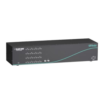
Page 16: The Front Panel
CHAPTER 2: Introduction 2.3 The Front Panel The front panels of the ServSwitch feature two or three pushbutton switches and several LED indicators. To familiarize yourself with these controls and indicators, refer to Figures 2-1, 2-2, and 2-3 below and the descriptions that follow on the next page. - Page 17 SERVSWITCH™ Panel Label Description POWER (left) Main Power LED: Lights to indicate that unit is powered ON. ON/OFF 2-port units only: Press this button to turn the ServSwitch ON or OFF. [Numbered] CPU Status LEDs: Numbered pairs of LEDs indicate the status of the CPU or submaster (cascaded) Serv device connected to the corresponding port on the rear panel: SELECT or [unlabeled left] (red)
-
Page 18: The Rear Panel
CHAPTER 2: Introduction 2.4 The Rear Panel All cable connections are made at the rear panel of the ServSwitch, as illustrated in Figures 2-4 and 2-5 and described below. Figure 2-4. The rear panel of a 2 to 1 ServSwitch (SW721A-R5). Figure 2-5. - Page 19 SERVSWITCH™ Panel Label Connector Description or Control CPU N DB25 F For each submaster you plan to connect, you (continued) must have an Expansion Cable; you must have an Adapter Cable for each CPU you plan to connect. See Section 2.5 NOTE The 2-port (mini) chassis has 4 CPU N connector...
-
Page 20: Cable Requirements
See Appendix B and the first Caution notice on page 22. To share an IBM 9515, 9517, or 9518 monitor on a ServSwitch, you will need special cabling. Call Black Box for technical support; we can give you a quote on these types of cable. -
Page 21: Installation
SERVSWITCH™ 3. Installation 3.1 Quick Setup Guide Figure 3-1, below, shows a basic example of connecting a CPU, a submaster, a keyboard, a monitor, and a mouse to the ServSwitch unit. Connectors will vary depending on the types of equipment you are installing. Figure 3-1. -
Page 22: Installation Procedure
Chapter 3: Installation 3.2 Installation Procedure This section provides complete instructions for the hardware setup of a single ServSwitch. (For detailed instructions on the capabilities and concerns involved in installing a cascaded Switch system, see Section 3.3; to make troubleshooting the installation easier, we recommend that you check the master and each submaster as it is installed, rather than installing all units, then checking the entire cascade.) For an illustrated example of the elements of a basic setup, see Figure 3-1 on the... -
Page 23: Connecting Cpus
SERVSWITCH™ 3.2.3 Connecting CPUS CPU Adapter Cables run from the ServSwitch to the keyboard port, mouse port, and video-output port of each CPU you want to directly attach to it. Different types of this cable fit the connectors on different computers (see Appendix B). This cable also comes in the different lengths supported by different applications (see Section 4.1.3). -
Page 24: Connecting Submasters (Optional)
MONITOR/KEYBOARD/MOUSE A ports, and the CPU ports of the other master to the submasters’ MONITOR/KEYBOARD/ MOUSE B ports. Before installing an advanced configuration, please call Black Box and discuss your application with a technician. -
Page 25: Powering Up The System
SERVSWITCH™ 3.2.5 Powering up the system 1A. 2-port model (SW721A-R5): Making sure that the connected CPUs and any connected submasters are OFF (powered down), take the output cord of the ServSwitch’s power supply and plug its 5-pin DIN male connector into the power jack on the rear panel of the Switch. -
Page 26: Changing The Keyboard Settings Of Windows Nt 4.0 Cpus
Chapter 3: Installation 3.2.6 Changing the keyboard settings of Windows NT 4.0 CPUs If any CPUs attached to your ServSwitch are running Microsoft Windows NT 4.0, you must change the keyboard setting in their Control Panel from the default, “Microsoft Enhanced Keyboard,” to “Standard 101/102 or Microsoft Natural Keyboard.”... -
Page 27: Cascading In Servswitch Systems
SERVSWITCH™ 3.3 Cascading in ServSwitch Systems In a normal cascaded ServSwitch system, the shared monitor(s), keyboard(s), and mouse (mice) are directly attached to one or more “master” Serv-Switches, while all the CPUs are indirectly attached through “submasters” (subsidiary ServSwitches, ServSwitch Ultras, ServManagers, etc.) that provide port expansion but may or may not perform any control functions of their own. -
Page 28: Cable Requirements For Expansion
Chapter 3: Installation say that CPUs 1 through 8 are “shared,” we mean that they can be accessed by either master at different times, not by both masters simultaneously.) Adding a third 4-port submaster unit would give you a total of 17 ports, and so on. (To reach all of the CPUs in cascaded systems like this, you must set Maximum computers, Width, and Units properly on the master unit;... - Page 29 SERVSWITCH™ Figure 3-2. Basic ServSwitch cascading.
- Page 30 Chapter 3: Installation • You must not cascade submasters to more than one “layer.” That is, you may connect submasters to the CPU ports of one or (with Matrix ServSwitch submasters) two master ServSwitches, but do not connect any submasters to submasters’...
- Page 31 SERVSWITCH™ • If you are attaching more than one submaster to a slimline or full-size master ServSwitch, we strongly recommend that all of the submasters have the same number of ports. This is because the Switch’s “Expansion width” command/ parameter—the value it uses to calculate how many ports each attached submaster has (see Section 5.2.5)—is global rather than submaster-specific.
- Page 32 Chapter 3: Installation If you see this, you will need to download correct firmware to the affected unit as described in Section 4.4.3, starting at the point at which the unit is ready to receive the file at 9600 baud (9600 bps). (In this case, you must download the file at 9600 bps.) 6.Turn ON the computer identified as CPU 1.
-
Page 33: Operation: Hardware And Keyboard Commands
SERVSWITCH™ 4. Operation: Hardware and Keyboard Commands The first part of this chapter, Section 4.1, gives you some guidelines that you should follow to make sure your ServSwitch works properly with your equipment. Section 4.2 summarizes the ServSwitch’s keyboard commands, and Section 4.3 describes these commands in detail. -
Page 34: Mouse And Keyboard
Chapter 3: Installation 4.1.2 Mouse and keyboard When you power up your ServSwitch system, make sure that your CPUs, mouse (mice), and keyboard(s) are properly cabled to the Switch (or to the appropriate master or submaster unit). When you boot up your CPUs, the master(s) and/or submasters to which they are connected should already be ON. -
Page 35: Monitor
SERVSWITCH™ However, we cannot guarantee that the ServSwitch will be able to fully support—or even work at all with—any keyboard that uses nonstandard keys, connectors, or keyboard-scan modes. 4.1.3 Monitor NOTE At resolutions up to 800 x 600, the video quality for most ServSwitch applications will be excellent. - Page 36 Chapter 3: Installation Coaxial cables (required for XGA applications and recommended for most other applications) do much better at maintaining video quality, as shown in Table 4-3 below. (For the meaning of quality numbers 3, 2, and 1, see the bottom of the previous page.) As before, the distances in the table are total cable lengths measured from the CPU to the monitor.
- Page 37 SERVSWITCH™ The ServSwitches will support SVGA (Super VGA) video, but with original Serv cables the video quality will decrease markedly at higher resolutions and distances. Table 4-2, below, illustrates this. The distances in the table are total cable lengths measured from the CPU to the monitor. The table assumes that one ServSwitch is between the CPU and monitor;...
-
Page 38: Keyboard-Command Summary
Chapter 3: Installation 4.2 Keyboard-Command Summary Table 4-4 below and on the next page summarizes the commands that can be sent to the ServSwitch. To enter any command at the shared keyboard, first press and release the left Control key, represented by “[Ctrl].” (This cues the Switch to look for commands from that keyboard.) Then enter the command followed by any arguments you wish to specify (the port number, for example). - Page 39 SERVSWITCH™ Table 4-4. The ServSwitch’s Keyboard Commands (continued) Command Keystroke Description Sequence Scan OFF Turns Scan mode OFF (the port being scanned at [Ctrl] X the time the command is entered is given access to the shared monitor, keyboard, and mouse). Note: Scan can also be stopped by entering a Select Port command.
-
Page 40: The Commands In Detail
Chapter 3: Installation 4.3 The Commands in Detail 4.3.1 Selecting a port from the shared keyboard To select a port from your keyboard, press and release your keyboard’s left Control key ([Ctrl]), then type in the port number: If “Maximum Ports” is set to 1 to 9: The ServSwitch will immediately switch to the desired port when you press the one-digit number’s numeral key. -
Page 41: Scan Mode
SERVSWITCH™ 4.3.3 Scan mode To start scanning (switching from CPU to CPU in a continuous rotation) from the keyboard, press and release the left Control key ([Ctrl]), then press [S]. The ServSwitch will begin scanning sequentially from its currently selected port through the higher-numbered ports, then begin again at CPU Port 1. -
Page 42: Reset
Chapter 3: Installation 4.3.6 Reset This command, along with the commands described in the next two sections, can come in handy when certain problems arise. It will reboot your keyboard and mouse without your having to power down the station or the system, and will also re-enable PS/2 mouse communication if the selected CPU has previously disabled it. -
Page 43: Identify Rom
SERVSWITCH™ 4.3.8 Identify ROM Unfortunately, as with all complex equipment, problems might arise with your ServSwitch that require the assistance of technical-support personnel. One of the things technicians might want to know when they attempt to diagnose and correct your problem is the revision level of your Switch’s ROM. This command causes the ServSwitch to send the four-character “UPxx”... -
Page 44: Log Out
Chapter 3: Installation 4.3.12 Log out If an access password has been set for your ServSwitch system (see Section 5.5.2), you can use this command to log out (to relinquish access rights) when you’re finished with a session at a user station. This will cause the ServSwitch to display an “Enter password”... -
Page 45: Switching Ports Remotely (Optional)
SERVSWITCH™ CAUTION! Serial cabling in excess of 50 feet (15.2 m) should be routed with caution. The maximum cable length depends upon the construction of the cable and its routing. For extended runs, shielded cable should be used. Avoid routing near fluorescent lights,... -
Page 46: Upgrading The Firmware (Flash Memory)
FTP site—at the time of this writing, you would use the “ftp://ftp.blackbox.com/pub/connectivity” directory—or from our Black Box BBS—call (724) 746-7120. For regular -R5 level ServSwitches, filenames will follow these formats: “UPxx.HEX,”... - Page 47 1 and sends “Waiting for file...”. To abort, press “N” on the PC’s keyboard; the Switch skips ahead to the “Hit enter to boot” message shown in step 5, but the firmware will remain unchanged. If the trouble recurs and you can’t pinpoint it, call Black Box for technical support.
-
Page 48: B Upgrading The Firmware With The Dos Copy Command
It should then send the message: Hit enter to continue (If you get an error message at any time during this phase, call Black Box for technical support.) 7. Press the Enter (or Return) key again. The Switch should return to normal operation with port 1 selected (LED 1 lit). - Page 49 ``If, however, an error occurs, LED 2 will remain dark, and there is a chance that the computer will lock up (you might have to reboot). If the computer is OK, you’ll have to go back to step 3. If the second attempt doesn’t work, call Black Box for technical support.
- Page 50 Once this phase is successfully completed, LED 3 will light. ``If, however, an error occurs, LED 3 will remain dark, and you’ll have to go back to step 3. If the second attempt doesn’t work, call Black Box for technical support.
-
Page 51: Audio, Serial, And Their Cables
SERVSWITCH™ 4.0 Audio, Serial, and their Cables ServSwitch supports serial pass-through or full stereo audio. Using a special CPU and KVM adapter cable, you can connect directly to a CPU’s sound card and to a pair of computer speakers or headphones at the KVM station. You can also, with special cables, connect to the CPUs MIC input and add a microphone to your KVM station. -
Page 52: Serial Connectivity
Chapter 4: Serial/Audio Features 4.2 Serial connectivity: The serial features of ServSwitch supports all pass-through serial devices such as Touch- screens and Graphic Tablets. Connect each computer to the corresponding ServSwitch’s CPU port using a CPU adapater cable configured with a DB25M connector on one end and a PS/2F keyboard and mouse connector, HD15M video connector, and a DB9F serial connector on the other end. -
Page 53: Operation: On-Screen Display
SERVSWITCH™ 5. Operation: On-Screen Display 5.1 Overview You can use the ServSwitch’s on-screen display to: 1. Configure the ServSwitch through a series of configuration menus (triggered with the [Ctrl] [F12] command, where [Ctrl] is the left Control key). 2. Switch to different computers from a window which shows a list of computer names (triggered with the [Ctrl] [ESC] command, where [Ctrl] is the left Control key). -
Page 54: Navigating The Configuration
Chapter 5: Operation: On-Screen Display This menu and all other on-screen display windows appear “on top of” your computer video, assuming you are switched to a computer with active video. (If no video is present, then the background is black.) If the display is not synchronized, then you should switch to a computer with active video and configure the resolution setting from the “Configure overlay”... -
Page 55: The "Configure System
SERVSWITCH™ 5.2 The “Configure System” Page Use this page, shown in Figure 5-2 below, to view and change keyboard-type, mouse, expansion, scan, and keyboard-typematic settings. Access it from the main menu by hitting [Enter] when “Configure system” is highlighted. Figure 5-2. The “Configure system” page. 5.2.1 Configure system: Keyboard Normally the ServSwitch will autodetect the keyboard type, but you can set it differently in this field if you need to. -
Page 56: Configure System: Mouse
Chapter 5: Operation: On-Screen Display 5.2.2 Configure system: Mouse The ServSwitch will also autodetect the mouse type unless you boot the Switch without a mouse attached, in which it will default to the “PS/2” setting. To change the mouse type, press [Enter] while “Mouse” is highlighted. An input-selection box will pop up as shown in Figure 5-3 below. - Page 57 SERVSWITCH™ “Serial 2-button mouse” refers to those mice that have serial RS-232 interfaces (usually with a DB9 connector), are Microsoft compatible, and use a 3-byte, 7-bit, 1200-bps, no-parity data format. Most PC serial mice with two buttons fall into this category.
-
Page 58: Configure System: Maximum Computers
Chapter 5: Operation: On-Screen Display 5.2.3 Configure system: Maximum computers This setting corresponds to the number of computers (CPUs) connected to the ServSwitch system. It comes in handy when you are cascading, or are only using some of the CPU ports on a single Switch: When the Switch knows how many CPUs there are, it can handle switching and scanning more intelligently. -
Page 59: Configure System: Expansion Units
SERVSWITCH™ 5.2.4 Configure system: Expansion units This setting corresponds to the number of “submaster” (expansion) Serv units that are connected to the main master ServSwitch. It helps to determine which CPU number is associated with which physical connector. If you aren’t cascading, this number should be set to zero. -
Page 60: Configure System: Scan Time
Chapter 5: Operation: On-Screen Display 5.2.6 Configure system: Scan time This item determines the time, in seconds, that the ServSwitch will pause at each of the computers when scanning. The factory-default setting is 5 seconds. To change the scan time, press [Enter] while “Scan time” is highlighted. An “Input new value” box appears. -
Page 61: Configure System: Typematic Delay
SERVSWITCH™ Table 3-1. Typematic Rate Rate Value Actual Rate in Rate Value Actual Rate in Keystrokes per Keystrokes per Second Second 10.9 13.3 17.1 18.5 21.8 26.7 5.2.10 Configure System: Typematic Delay This item determines how soon keystrokes will begin to repeat after the operator begins holding down a key on the shared keyboard. -
Page 62: The "Configure Computers
Chapter 5: Operation: On-Screen Display 5.3 The “Configure Computers” Page Use this page to set the name, keyboard type, and mouse type for each of the ServSwitch’s CPU ports. Access it from the main menu by hitting [Enter] when “Configure computers” is highlighted. The page is shown below in Figure 5-5. (The arrow in the column after the computer number points to the currently selected computer.) Figure 5-5. -
Page 63: Configure Computers: Computer Name
SERVSWITCH™ 5.3.1 Configure Computers: Computer Name Each computer can be given a name consisting of up to 16 characters. These names appear as labels in the “Computer select” window (see Section 5.6). To change a computer name, press [Enter] while the corresponding “Computer name”... -
Page 64: Configure Computers: Keyboard
Chapter 5: Operation: On-Screen Display 5.3.2 Configure Computers: Keyboard Use this field to tell the ServSwitch what type of keyboard mode (PC mode 1, 2, or 3) a given CPU uses. To change a CPU port’s keyboard mode, press [Enter] while the corresponding “Keyboard”... -
Page 65: Configure Computers: Mouse
SERVSWITCH™ 5.3.3 Configure Computers: Mouse Use this field to tell the ServSwitch what type of mouse a given CPU uses. The factory default is “PS/2” (non-wheel). To change a CPU port’s mouse type, press [Enter] while the corresponding “Mouse” field is highlighted. A mouse-type input box appears, as shown in Figure 5-8 below. -
Page 66: The "Configure Overlay
Chapter 5: Operation: On-Screen Display 5.4 The “Configure Overlay” Page Use this page to set the color of the configuration menus, the resolution of ServSwitch-generated video, the type and timing of the Switch-generated screen saver, the appearance of the “Computer select” window, and the appearance of the Switch-generated computer label (see Section 5.4.3.A). -
Page 67: B Resolution
SERVSWITCH™ 5.4.1.B Resolution This item gives you maximum monitor-type flexibility by determining the resolution and refresh rate of the video signal that the ServSwitch sends to the shared monitor while the unit isn’t receiving any video from the CPU. The possible choices—all using 640 x 480 resolution—are “PC1”... -
Page 68: Configure Overlay: Computer Select Window
Chapter 5: Operation: On-Screen Display 5.4.2 Configure Overlay: Computer Select Window 5.4.2.A Background Color and Text Color These items determine the background and text colors of the “Computer select window” (see Section 5.6). The “solid” colors available are black, red, green, yellow, blue, magenta, cyan, and white;... -
Page 69: Configure Overlay: Computer Label
SERVSWITCH™ 5.4.3 Configure Overlay: Computer Label 5.4.3.A Background Color and Text Color These items determine the background and text colors of the computer label. The ServSwitch displays this label on the shared monitor’s screen as you switch between CPUs to identify individual CPUs. The “solid” colors available are black, red, green, yellow, blue, magenta, cyan, and white;... -
Page 70: C Show Computer Number
Chapter 5: Operation: On-Screen Display 5.4.3.C Show Computer Number This item determines whether or not the computer number is displayed along with the computer label. To change this setting, press [Enter] while “Show computer number” is highlighted. A yes/no input box appears. Use the arrow keys to select “Yes”... -
Page 71: The "Configure Security
SERVSWITCH™ 5.5 The “Configure Security” Page Use this page to set security options for the ServSwitch. Access this page, shown in Figure 5-10 below, from the main menu by hitting [Enter] when “Configure security” is highlighted. Figure 5-10. The “Configure security” page. 5.5.1 The Configure Password This option protects the configuration settings of the ServSwitch system from unauthorized changes. -
Page 72: The Access Timeout
Once you have successfully set these passwords, you should keep a record of them in a secure location; if nobody can remember a given password, you will have to call Black Box Technical Support for help to recover your system. To remove either of these passwords, delete the password and press Enter with... -
Page 73: The "Computer Select Window
SERVSWITCH™ 5.6 The “Computer Select Window” You can bring up a “computer select window” on the shared monitor’s screen to select a specific computer from a list of computers attached to the ServSwitch. Access the window, shown in Figure 5-11 below, by pressing and releasing the left [Ctrl] key and then hitting the [Esc] (escape) key. -
Page 74: Troubleshooting
Now reconfigure the box to your desired settings. If you’re still having difficulty, refer to Section 6.2. If it doesn’t help you to solve your problem, call Black Box for technical support. -
Page 75: Common Problems
CPU that’s having the problem. If the CPU boots, the ServSwitch or submaster might be defective; call Black Box. H. If the CPU still doesn’t boot, the CPU’s keyboard or mouse port (or other components) might be defective. -
Page 76: Can't Switch Ports From Keyboard
CHAPTER 6: Troubleshooting 6.2.2 Can’t Switch Ports from Keyboard A. Can you do anything from the keyboard? If not, the keyboard strand of your MKM cable has probably come loose. Reconnect it. B. The ServSwitch might have lost power for less than three seconds. (This can cause the keyboard to lock up.) Disconnect the keyboard and plug it back in. -
Page 77: Servswitch Scans Or Switches To Empty Ports
SERVSWITCH™ 6.2.5 ServSwitch Scans or Switches to Empty Ports A. The “Maximum computers” setting is too high. (If any of the CPUs you can access are receiving garbage characters, this is a good indicator.) Set Maximum Ports to match the number of CPUs in your system. See Section 5.2.3. B. -
Page 78: Mouse Doesn't Move Pointer/Cursor
A. If you are trying to use an IBM 9515, 9517, or 9518 monitor, you need special cables to carry the video correctly. Call Black Box for technical support. B. Check the settings of your monitor, especially the sync or color controls. -
Page 79: Can't Access High Resolutions Mode
SERVSWITCH™ E. The CPU is sending video with sync on green, which the ServSwitch does not currently support. Call Black Box for technical support. F. If the video problem is not centered on the monitor, check the video strands of your cables. -
Page 80: Calling Black Box
6.2.17 Lost Password If you’ve lost your access password or configuration password and you have no record of what they are set to, you will have to call Black Box Technical Support. They will help you to recover your system. -
Page 81: Appendix A: Nvram Factory Defaults
SERVSWITCH™ Appendix A: NVRAM Factory Defaults A.1 Keyboard-Command Settings The tables below shows, for the ServSwitch’s keyboard-command configuration options, the default values stored in nonvolatile memory (NVRAM) when the ServSwitch is shipped from the factory. It also shows what commands or actions can change these settings for the Switch’s current operating period, as well as what commands or actions (if any) can save changed settings to NVRAM, so that they become the new defaults. -
Page 82: A.2 On-Screen Configuration Settings
APPENDIX A: NVRAM Facory Defaults A.2 On-Screen Configuration Settings The table below and on the next page shows, for the ServSwitch’s saveable onscreen display options, the default values stored in nonvolatile memory (NVRAM) when the ServSwitch is shipped from the factory. Option Default setting System... - Page 83 SERVSWITCH™ Option Default setting Computer label Background color....... Transparent blue Text color........White Position........X=3, Y=90 Show computer number .... Yes Fade out ........5 seconds Font ..........16 x24 modern Security Configuration password..... None Access password ....... None Access time........ 999 seconds (16 hours, 39 minutes)
-
Page 84: Appendix B: Cable Product Codes
CPUs as much as 200 ft. (61 m) away. If your monitor/keyboard/mouse-sharing system has cabling requirements that can’t be met by what you see here, call Black Box for a possible quote on custom cables or adapters. - Page 85 SERVSWITCH™ Standard CPU Adapter Cables: Monitor Type Keyboard Type Mouse Type Product Code (Connector on Cable) (Connector on Cable) (Connector on Cable) VGA (HD15 male) IBM PC/AT (5-pin DIN male) Serial RS-232 (DB9 female) EHN048-0xxx VGA (HD15 male) IBM PS/2 (6-pin mini-DIN male) PS/2 (6-pin mini-DIN male) EHN051-0xxx Coaxial CPU Adapter Cable:...
-
Page 86: Appendix C: Pinout Of Rs-232 Port
APPENDIX E: Rackmount Appendix C: Pinout of RS-232 Port The table below shows the pinout of the ServSwitch’s RJ-12 (“6-wire RJ-11”) female RS-232 port. Pin Signal Name Abbrev. Direction Description Data Set Ready Input Reserved (not used) Data Terminal Ready DTR Output Pulled high with 1-K. -
Page 87: Appendix D: The Lk461 Keyboard
SERVSWITCH™ Appendix D: The LK461 Keyboard Some of the computers manufactured by Compaq subsidiary Digital Equipment ® Corporation come with a special keyboard called the DEC LK461. The ServSwitch supports this keyboard by passing through unaltered the scan codes of certain proprietary keys (such as [Help] and [Do]) and remapping others (such as [PF1] through [PF4]). - Page 88 APPENDIX E: Rackmount Appendix E: Rackmounting the ServSwitch If you want to mount your -R5 ServSwitch in a 19", 23", or 24" rack, make sure you get the right ServSwitch Rackmounting Kit: product code RMK19M, RMK23M, or RMK24M respectively for the mini-chassis Switch models, RMK19B, RMK23B, or RMK24B respectively for the slimline-chassis models, or RMK19C, RMK23C, or RMK24C respectively for the full-size-chassis models.
- Page 89 The audio feature of ServSwitch supports typical audio levels produced from a computer sound card's Speaker output. Powered speakers can be used for increased volume. © Copyright 2013. Black Box Corporation. All rights reserved. SW721A-R5, Addendum 724-746-5500 | blackbox.com Page 1...
-
Page 90: Serial Connectivity
ServSwitch KVM Switch Instalation Manual Addendum Connect each computer to the corresponding ServSwitch’s CPU port using a CPU adapter cable configured with a DB25M connector on one end and a PS/2 key- board and mouse connector, HD15M video connector, and 2-3.5mm Stereo audio connector on the other end (speaker and microphone input). - Page 91 ServSwitch KVM Switch Instalation Manual Addendum Connect each computer to the corresponding ServSwitch’s CPU port using a CPU adapter cable configured with a DB25M connector on one end and a PS/2F keyboard and mouse connector, HD15M video connector, and a DB9F connector on the other end.
- Page 92 724-746-5500 or blackbox.com. About Black Box Black Box provides an extensive range of networking and infrastructure products. You’ll find everything from cabinets and racks and power and surge protection products to media converters and Ethernet switches all supported by free, live 24/7 Tech support available in 30 seconds or less.
Need help?
Do you have a question about the ServSwitch SW721A-R5 and is the answer not in the manual?
Questions and answers