Advertisement
Quick Links
Advertisement

Related Manuals for sitrex MK14 MY15


Summary of Contents for sitrex MK14 MY15
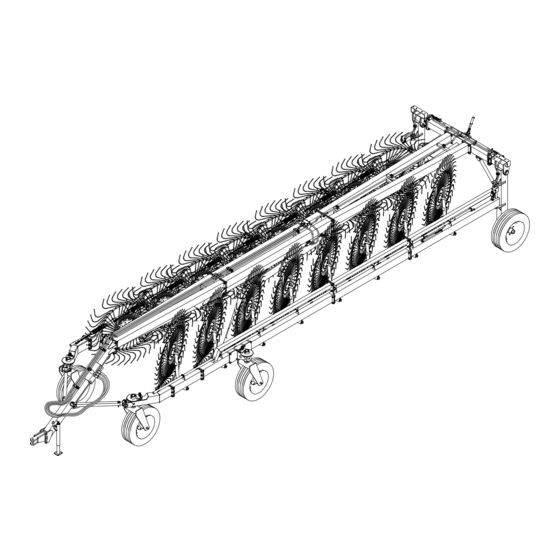
- Page 1 ASSEMBLY MK/14-16 MY15 09-14 (TEMPORARY ASSEMBLY)
- Page 2 Assembly Instructions Examples of general measurements for identifying assembly accessories according to type. To make it easier to identify the assembly accessories (nuts, bolts, washers, pins, etc.) on the basis of the general dimensions and the type, we provide a diagram that shows you the accessory parts to which the measurements refer as given in the various steps of assembly.
- Page 3 Assembly Instructions Examples of general measurements for identifying accessories for assembly according to type. For tightening torques, see the table below (the class of the material is normally stamped on the head of the bolts).
- Page 4 General assembly instructions for all models in the MK series. regards indicating right/left, they are understood to be attributed observing the machine from point A (behind the machine) looking forward. The machine must be assembled in a suitable area, done by qualified personnel equipped with the proper clothing, protective equipment and tools necessary for the job.
- Page 6 DANGER Insert bushings 4 in the openings in supports 2-3 (RH/LH - 40kg/88lbs). Lift unit 1 (weight 110kg/245lbs) with a suitable forklift W. Connect the vertical supports 2-3 to the crosspiece assembly 1 using pin 5, washers 6-7 and bolt 8. Insert the grease nipples 9 into the openings in supports 2-3 and in the crosspiece assembly 1.
- Page 7 DANGER The tie rod 4 is preassembled to the right size for it to be attached to seat A on the crosspiece assembly 1 and to seats C on the vertical supports 2-3. Part B of tie rod 4 goes to seat A on the crosspiece assembly 1 and part D goes to seat C on the vertical supports 2-3.
- Page 8 DANGER Attach the wheel hubs 1 to vertical supports 2-3 using bolts 4 and nuts 5. Attach the wheels 6 to the hubs 1 and fasten with the special nuts 7. Note: the rounded part A of the special nut 7 should be applied facing the wheel 6.
- Page 9 DANGER Check that manufacturer has assembled on the vertical supports (RH-LH) the pins 5, spacers 6, washers 7 and nuts 8 that you will use for assembly in the order in which you find them assembled. Check that manufacturer assembled bushings B to their seats on sections 3-4 (RH- LH).
- Page 10 7) DANGER Check that pipe B protrudes about 288mm-11.34” from section 1-2. Note: this measurement is with the cylinder to which it is attached completely closed, and the total pipe length must be 1670 mm – 65.75”. Now attach sections 3-4 (RH-LH – 65kg/143lbs) to sections 1-2 (RH-LH) using bolts 5 and nuts 6.
- Page 11 8) DANGER Now attach sections 3-4 (RH-LH – 105kg/230lbs) to sections 1-2 (RH-LH) using bolts 5 and nuts 6. In this step, you will use: Item 5: 20 bolts M16x45 (0.63”x1.77”) - Item 6: 20 nuts M16 (0.63”) 9) DANGER Insert the nylon bushings 5 into the openings in sections 1-2 (RH-LH).
- Page 12 10) DANGER Attach the plate with bolt 2 underneath flange 1. Attach the counterplate 3 over flange 1, inserting the counterplate pins A into the holes in the plate with bolt 2 and into holes B in the sections. Place the bushing 4, spring 5 and washer 6 over the plate 2 bolt and put nut 7 on the bolt.
- Page 13 12) DANGER Note: Sections 3-4 (RH-LH) are to be assembled only for MK/16. Attach sections 3-4 (RH-LH) to sections 1-2 (RH-LH) using bolts 5 and nuts 6. Note: For MK/14 and MK/16 – At this point the assembly of the sections is completed.
- Page 14 13) DANGER Attach the wheel supports 3-4 to sections 1-2 (RH-LH) using bolts 5 and nuts 6. Apply grease nipples 7 to the seats in wheel supports 3-4. In this step, you will use: Item 5: 12 bolts M16x45 (0.63”x1.77”) Item 6: 12 nuts M16 (0.63”) Item 7: 2 grease nipples M8 (0.31”) 14) DANGER...
- Page 15 15) DANGER Check to make sure the manufacturer has correctly secured the bushings C with retaining rings D on all the RH and LH sections. In this assembly position holes F in pipes 1-3 are not used. Starting from bracket A for the 16-rake wheel machine and from bracket B for the 14-rake wheel machine, insert pipe 1 (L.2515mm-99.01”) into all the brackets B until reaching pipe E already assembled by the manufacturer.
- Page 16 16) DANGER Carry out this operation very carefully and with suitable lifting equipment because the drawbar 2 is heavy and bulky. Weight 170kg/375lbs. First of all remove the nut A and packing retainer B from the crosspiece assembly 1. The nuts A and packing retainers B will not be reused.
- Page 17 18) DANGER Carry out this operation very carefully and with suitable lifting equipment because the drawbar 2 is heavy and bulky. Weight 135kg/297lbs plus the preceding drawbar. To work safely and make the next assembly easier, set the drawbar 2 on a support A. Attach drawbar 2 to drawbar 1 using bolts 3 and nuts 4.
- Page 18 20) DANGER Attach the safety chain 1 to the holes A in the drawbar using the bolt 2, washer 3 and nut 4. Attach the canister 5 to seats B on the drawbar using bolts 6, washers 7 and nuts 8. In this step, you will use: Item bolt...
- Page 19 22) DANGER Attach the opening arms 3-4 (RH-LH) to sections 1-2 by means counterplates bolts 6 and nuts 7. theoretic measurements given assembly of arms 3- 4 and counterplates 5. At this stage do not fully tighten nuts 7, because when the cylinders attached (see step necessary to move...
- Page 20 24) DANGER Insert brackets 2 in the slots A in all the pipes (RH-LH). Attach the chain 3 at all the brackets 2 using the bolt, washer 5 and nut 6. In this step, you will use: Item 2: 14-16 chain brackets - Item 3: 14-16 chains, length 820mm (32.3”) Item 4: 14-16 bolts M10x25 (0.4”x1”) - Item 5: 14-16 washers ø11-30x2.5 (ø0.43”-1.18”x0.1”) - Item 6: 14-16 nuts M10 (0.4”) 25) DANGER...
- Page 21 25) DANGER In this step, you will use: Item 1: 28-32 nylon bushings ø35-42x26 (ø1.38”-1.65”x1”) Item 4: 14-16 washers ø35-50x5 (ø1.38”-1.97”x0.19”) Item 5: 14-16 spring pins ø8x50 (ø0.31” x 1.97”) Item 8: 84-96 bolts M10x25 (0.39”x1”) Item 9: 84-96 split washers ø10.5-17x2.5 (ø0.41”-0.67”x0.1”) Item 10: 84-96 nuts M10 (0.39”)
- Page 23 26) DANGER Hook X on spring 1 is more closed than hook Y. Hook Y (the more open one) should be inserted into hole Z in the lever of arms 2-3 (RH-LH). First of all pass chain K, which is screwed onto the rake wheel lifting pipes, through the spring 1.
- Page 24 27) DANGER Note: Spread open the machine in order to have more room to work in. There are two hydraulic cylinders complete with valves, one set up for the RH side indicated by reference 1 and one for the LH side indicated by reference 2. The assembly is correct when the valve is on the upper part of the cylinder and when holes A-B are facing the outside of the machine.
- Page 25 28) DANGER Extend the hose 1 along the drawbar until the female end is near bracket A. Connect the female end of hose 1 to the T coupling 2. Connect the elbow couplings 3 to the T coupling 2. The assembled hose and couplings unit 1-2-3 are placed underneath bracket A so that the couplings 3 are at the back of it.
- Page 26 29) DANGER Apply washers 2 and nipples 3 to holes A on the check valves of the RH and LH cylinders. Apply washers 2 and nipples 3 to holes B on the flow divider. Connect the curved end of hoses 4 to nipples 3 on the cylinder check valves. Connect the other end of hose 4 to nipples 3 on the flow divider without fastening completely.
- Page 27 30) DANGER Apply washers 2 and nipples 3 to holes C on the check valves of the RH and LH cylinders. Connect the curved end of hoses 4 to nipples 3 on the cylinder check valves without tightening completely. Connect the other end of hose 4 to couplings D located underneath the flow divider bracket without fastening completely.
- Page 29 31) DANGER (see drawing on preceding page) Connect coupling 1 to cylinders A using washers 2 and bolts 3. Apply nipple 4 to coupling 1. Apply washer 2 and valve 5 to nipple 4. Apply washer 2 and nipple 6 to valve 5.
- Page 30 32) DANGER Send hose 11 under bracket A and continue to secure it with collars 3 and screws 4. Apply washer 6 and nipple 5 to hole B on the flow divider. Bring the female end of hose 2 near the nipple and extend it along drawbar C toward the front of the machine parallel to hose 1 already assembled.
- Page 31 33) DANGER Continue to secure hose 11 with collars 3 and screws 4. Continue to secure hoses 1-2 with collars 6, clamps 7 and bolts 8. Bring the female end of hose 5 near the male end of hose 11 and extend it along drawbar C toward the front of the machine parallel to hoses 1-2 already assembled.
- Page 33 34) DANGER Continue to secure hose 5 with collars 3 and screws 4. Continue to secure hoses 1-2 with collars 6, clamps 7 and bolts 8. Connect the quick-release couplings 9 to the male ends of hoses 1-2-5. In this step, you will use: Item 1,2,5: see preceding step Item 3: 6 collars ø18 (ø0.71”) Item 4: 6 cheese head screws M6x25 (0.24”x1”)
- Page 35 35) DANGER The assembly is now completed. The machine is ready to be lubricated and then used. If for lubricating or for other reasons the machine must be moved, the safety arms must be rotated from the working position A-B to the transport position A-C.
- Page 36 MAINTENANCE POINTS AND INSTRUCTIONS...
- Page 37 MAINTENANCE POINTS AND INSTRUCTIONS Every x Pos. Qty. Description Operation hours Rear crosspiece Lubricate 50 (A) Opening tie rod Lubricate 50 (A) Vertical support Lubricate Rear wheel hub Lubricate Section joint pin Lubricate 50 (A) 14-16 Rake wheel arm joint Lubricate Pirouetting wheel support Lubricate...
- Page 38 Zona Industriale-Viale Grecia, 8 06018 TRESTINA-(Perugia)-ITALY Tel. +39.075.8540021-Telefax +39.075.8540523 e-mail: sitrex@sitrex.it www.sitrex.com...
Need help?
Do you have a question about the MK14 MY15 and is the answer not in the manual?
Questions and answers