Advertisement
Quick Links
Advertisement

Subscribe to Our Youtube Channel
Related Manuals for Global BM 360


Summary of Contents for Global BM 360
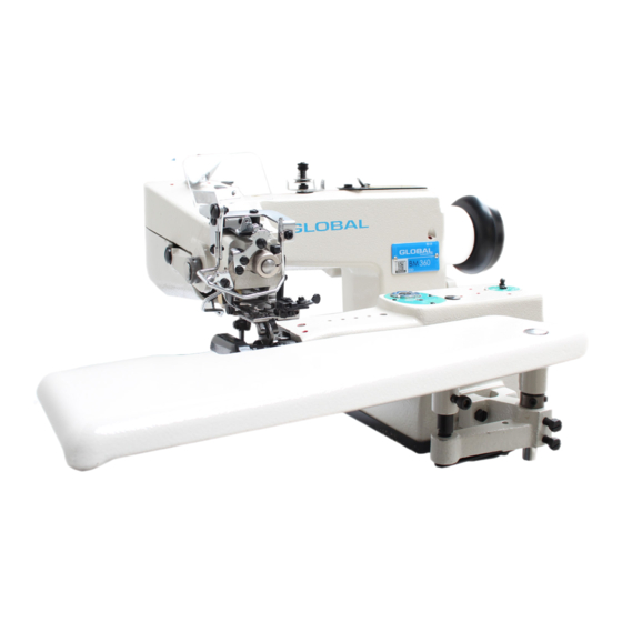
- Page 1 BM 360 - BM 364 Blindstitch felling machi � e spare parts & instru4tion manual...
-
Page 3: For Safe Operation
FOR SAFE OPERATION 1 . Safety symbols and definitions Alert and illustration symbols are affixed on this instruction, our sewing machine, and device in order to prevent personal injury or danage for the safe operation. The symbols and their definitions are as follows: (1) Alert symbols This sign shows that wrong handling by negl ecting �WARNING... - Page 4 - 19 - FOR SAFE OPERATION CAUTION FOR HIGH TEMPERATURE: DO NOT TOUCH STEPP ING &, MOTORAND SOLENO ID Stepping motor and solenoid may overheat if used continuously. ;i!l;ill.iHI!. To prevent a burn, take care not to touch. This caution label CAUTION for high temperature is affixed on these parts for calling attention.
- Page 5 FOR SAFE OPERAT I ON Working environment � FOR SAFETY, DO NOT WORK IN THE FOLLOWING ENVIRONMENTS: (D The where atmosphere temperature and humidity give a bad influence the performance of sewing machine. ® The outdoors and the where sunlight is exposed directly. •...
-
Page 6: Caution Before Operation
Never connect the plug to power supply until assembly is finished. Fix securely the cable connectors connecting the sewing machine head, motor, and electric apparatus . Be sure not to apply excessive tension to the connection cables. Connect the cables near the driving parts apart from them. Take an earth to the designated position on the machine head. -
Page 9: Installation Of Belt Cover
Bolt Bolt (1(6-1 x 50) Felt Pad 1------ Receiver Seal �-Oil Receiver �- �>---Jasher ®--Nut � 1 -3 Installation of Belt Cover For safe operation, be sure to install Belt Cover (Middle) and Belt Cover(Lower) and operate Machine. Belt Cover :·-�(lliddle) •... -
Page 10: Motor And Belt
2. Sewing speed and rotating direction The maximum sewing speed of this machine is 3,000 s.p.m. However, for the durability of the machine, it is recommended to operate at the speed of 2,500 s.p.m. for the initial one week and increase the speed gradually since then. - Page 13 Stitch Stitches per 5-8 Ad j us tme nt of s tit eh I en g th length 30mm inch Stitch length can be adjustde in 6 stages from 8.5mm 3. 2mm to 8. 5mm. 6. 4mm 4. 7 The right table shows stitch length and number of 5.
- Page 19 CM-364 et the stitch length to "8. 5" when making the following adjustment . When Main Feed Dog(A) comes to the foremost position, with the distance of 10mm between Need and the tip of the Feed Dog, fix the Feed Needle Dog with Screw (B).
- Page 21 Parts Amt. Req. Description Machine Frame Unit 4010000 • I Top Cover • • • • . ffii&,jj. 0080746 000559 Conical Spring Washer • • 1 . ii * 006147 Screw(3/16-32X6. 4) • 0080144 Head Cover (Rear) • � Jlft ,jj . .
- Page 22 32-, r-,,__ , ..-- • ,,.= --.: • • • .. . • -36-...
- Page 23 THREAD EYELETS. BUSHINGS & OILING SPOTS Ref. Parts Amt . l'b. l'b . Description Req . {i/, 4010008• Thread Tension Mechanism, C. Set it �::fJffl.{4 · 000182 Thread Tension Spring Adjusting Nut )Eii,!ll;. jf i,'113!1!1-lij: 0020126 Tension Spring Bushing )Eii,!11;.jflf.i!li • 0020125 Thread Tension Spring •...
- Page 24 -38-...
- Page 25 & Ref . Parts N:J. Description 4010042 Eye Guard, C. Set • Eye Guard Support 4010044 Eye Guard • 4010043 Screw (M2 . 5-0. 45 X 4 . 5) 110038 Screw(ll/64-40X9. 7) 006004 000010 Conical Spring Washer • Nut • •...
- Page 27 IEEDLE DRIVING MECHANISM Amt. tef. Parts £ lilt Req. Description . litffl'� • Pu 11 ey 0080145 . !II # . Screw(l5/64-28Xl7. 5) 003595 Ill . . fc! Collar(l2. 71X21 X8mm) 0080123 ·4 Screw (7 /32-32X4 . 8) 003554 . .:£� . •...
- Page 28 ..✓ . • ..· . ,..,.,," • • • ·\�� -- • -------�--------,.- -::;: �- ·�� 'Z_ -42-...
- Page 29 • 1 ESSER FOOT MECHANISM(1) Arnt. Parts tilt Description N:i. � �-ffi 0080325 Spring Pin *�ff±.��- 0080309 Knee Press Shaft Spring· ffi-=f 000724 ffllI!I 0080308 Collar(9 . 53Xl9X6. 4mm) 004397 Screw (5/32-40 X 7. 1) fl-�ff-3:.�- 0080304 Knee Press Shaft fl-�ff��#c.
- Page 30 �- ...... -..... ,,,, .. > -44-...
-
Page 31: Presser Foot Mechanism
Ref. Parts Amt . Description Presser Foot Plate, 4017004 Complete Set ttl!Hll.# 4017006 Presser Foot Plate 4017007 Chaining Finger· 004246 Screw (11/128-56 X 2 . 4) • 1 0080358 Needle Guard . !fl # 004393 Screw (5/32-40 X 1. 9) 4017016 Cloth Guide·... - Page 32 1 � � "" -46-...
- Page 33 Ref. Parts Amt . It>. t-b. Description � 0080601 Ridge Forming Plate Eccentric t;I!# . 003559 • Screw(7 /32-32 X 7. 5) 003555 Screw(7/32-32 X 6. 4) t;I!# . 0080602 Skipstitch Eccentric 1"6f.l ffl ,.:,, :q; 0080624 Skipstitch Eccentric Pin 0080623 Main Shaft Gear Sypport •...
- Page 34 ➔ -48-...
- Page 35 Amt. Ref. Parts Description /ii, � N:i . fua..g_, 4010038 Ridge Form Regulator Graduation Plate • • 3 230007 Screw(29/256-48X5) • • /!!l # • 006520 Screw(7 /32-32X6) • • • Ridge Forming Regulator, C. Set • 0080690 5-1 0080693 Ridge Forming Regulator(l:O.
- Page 36 -50-...
- Page 37 .OOPER DRIVING MECHANISM Parts tef . Amt. N:J. N:J. Description � � 0080403 Looper Driving Crank Pin • tTlfi� dMfli$ffi . �llilflil 0080414 Oil Wick 0080215 Oil Retainer(without hole) • lf'llilff (�it) • 0080400 Looper Ori ving Crank, Complete Set tT:Ef-ffdbffi, ft'i: 0080401 Looper Driving Crank •...
- Page 38 • r -. '4.! ::;, -, 2 1 _ , .,,,. , .-- --· 30 - - 211 r· -52-...
- Page 39 FEED DRIVING MECHANISM " Parts Ref . Amt . 1-'i � !'b. Description 0080520 Feed Regulating Pushbutton, Set ttl!JB1'11tt-W.(ffl,f'I'·) • tt i'411 0080521 Feed Regulating Pushbutton llJl: ffl. • 1 0080523 Pushbutton Spring· • tt-W.iJ¥. 0080524 Pushbu tton Spring Sleave •...
- Page 40 �. �-- • • � : r ::_ '-J' '--� � _J '· = '-' - -5 4-...
- Page 41 Ref. Parts Description Req. 4011058 Machine Frame Unit 4011062 Machanism Cover • • • �i;IJ,l& • • 1 • l!I! # • • 004406 Screw(ll/64-40X8) · 2 4012082 • � i;IJ �J /l fl: • Differential Graduation • • !JIK #J :lt t&' 0080432 •...
- Page 42 IJl-3&4 .-· j)-5 I r--, ' � ' ... '.., ' ' ' " -56-...
-
Page 43: Extra Parts
Amt. Parts Description Thread Pull-off Device. C. Set • 1 4010020 Thread Eyelet Support 4010021 Screw(ll/64-40X10). 004437 Thread Guide Support 4010023 Screw (9/64-40X4) 007006 Thread Guide Holder 4010024 Screw (9/64-40X4. 5) 001203 Thread Guide • 1 4010025 Screw (9/64-40X3. 8) •... - Page 44 EXTRA PARTS -58-...
- Page 45 ACCESSORIES Ref. Parts Amt. Description ·U· ♦ 0099044 Machine Cover • ♦ -�'f . 9620003 Bag • • 1 . •*JJ ♦ 0099091 Screwdriver • . tt . ---- ♦ Needle (System: LWX6T #3) ♦ 0 099051 Thread Tweezers • .
- Page 46 •• <y ·r & • AT" DEY ICE 18--<> -60-...
Need help?
Do you have a question about the BM 360 and is the answer not in the manual?
Questions and answers