Advertisement
Quick Links
Advertisement

Subscribe to Our Youtube Channel
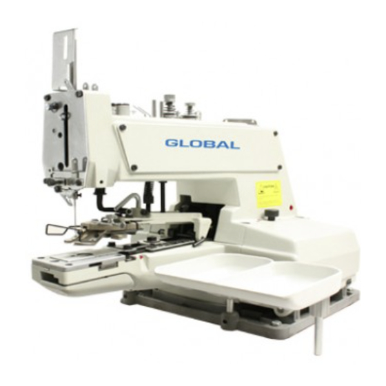
Summary of Contents for Global B5473
- Page 1 GLOBAL B5473 Instruction & parts Manual www.globalsew.com info@globalsew.com...
- Page 3 Before operating SINGLE THREAD CHAINSTITCH machine, please read this Instruction Manual Care BUTTON ATTACHING MACHINE fully in order to operate correct efficient manners. INSTRUCTION MANUAL Thanks your selec tion, wish like forever. CAUTIONS BEFORE OPERATION CAUTIONS IN OPERATION 1. The machine has been determined in facto1y, I.Never place your hands under the needle during operation.
- Page 4 4.HOW TO INSTALL THE 3. HOW TO INSTALL THE NEEDLE � --- ------------ --'. N EE DL E BA R GU ARD *Turn off the motor powr.r. I.Loosen setscrew ® Use a TQ 7#20 neerlle. 2.lnstall the needle I.Loosening needle setscrew bar guard CD uncle CD hold needle ®...
- Page 5 9.NEEDLE-TO-LOOPER RELATION '---' 10 >< 1 l O )( 7 tst: *Ser the meedle to looper relation in the following way: l .ln the state of the pedal was fully treaded. turn the pulley in the direction of rotation.bring down the needle bar to the lowest point.
- Page 6 Pulling the thread in the At first. please measure the hole distance . For the 4-hole arrow direction. rotate the button. the crosswise stitch width is the same as the driving pulley. now the longitude width. tension disc No. 2 was released.
- Page 7 *The clearance between the bullon cl *How lo install the button *Height of moving knife poke hook The clearance between the moving knife amp lifting lever and the adjusting bolt lifting rod. CD and the looper® is approx. 0.5-0.7 Make arljustmenl so that a clearance of Mount the follow parts on the but...
- Page 8 release of the tensity down at feed"plate. knife poke hook. is 9mm. Remedy T ruble Cause Making yoke slide working in coordination CD Yoke slide doesn't work well. 1. Needle thread with timing tension close. is broke Set the timing for the tension release of ®Wrong timing for the tension release of tension disc No.2 earlier.
-
Page 11: Table Of Contents
CONTENTS ..................BUTTON CLAMP MECHANISM COMPONENTS ARM & MISCELLANEOUS COVERS COMPONENTS ..................LOOPER SHAFT MECHANISM COMPONENTS NIPPER &... - Page 13 llcsc r iption l' L ,IT ll l lTTON C l.AMI' ASM. 15/64-28 l.=8 FJ65 SCREW BUTTON CLAMP LIFTING RO D E90116 FJ65 SCREW 15/64-28 !.=8 SCREW 3/16-32 L= I 3. 5 FJ5783 WASI IER 5 x 1 ll. 5 x I GB97.
- Page 15 E80217 FRONT COYER ASM. SCREW 11/64-40 L=8 F J 6 5 TENS 1 ON SPR IN(; E80201 NI PPER RELEAS 1 N(; PLIINCER E90211 E902201 TENSION ADJllSTlN(; TTAS E N O. 3 E902202 TllREAD T ENSI ON STllll E902203 TIIREAll l RESSER l'Li \ TE TENS ION Sl' R INC E902204...
-
Page 16: Looper Shaft Mechanism Components
LOOPER SHAFT MECHANISM COMPONENTS 36 37 3 839 40... - Page 17 Description TIIRl/S T BALL BEAR INC E80322 LOOPER SIIAFT Bl/SII INC, REAR E90323 SCREW 15/64-28 L=l 0. 5 FJ75 DR I VEN WOR M ASM. 280324 SCREW 1/4-40 L=7. U FJ?O. 1 CA M SHAFT DR I VEN GEAR ASM. E80325 SCREW 1/4-40 L=6.0 FJ80...
-
Page 18: Nipper & Thread Tension Parts Components
NIPPER & THREAD TENSION PARTS COMPONENTS... - Page 19 Description SCREW 15/64-28 L=12 FJ67 TIIREAIJ CII I DE E90401 111 NGE SCREW ll=7. 94 I I= 1 2. 7 E80405 NI I T 1/�-44 FJ6170 NllT E80403 TIIRE,\D NIPPER ASM. E8 04 04 TII R E,\11 RELEAS INC SCREW STIii) E80402 ILi R BLOCK SPRINC...
-
Page 20: Feed Plate Components
COMPONENTS .FEED PLATE 10111213 14 �: 'l1J' -?--- ,-:;-... , 4 Pt --- � l � J- 3 6 4 2 .(u-... - Page 21 Description r11n<·<-u11t·i: 1:1:i:n <'TI ,n r:on� 1, FIB) l'I.AIT.SMALL 13UTTON E80501 WA SI 11:R 5x I0.5x I GB97. I SCRl:W 3/16-28 L FJ5783 IINGE SCRl�W FOR CROSSWISE FEl:I) 1280526 INDICATOR PIN llEA RING BLOCK E80528 CROSSWISE FEED INDICATOR E80529 CROSSWISI: FLED INDICATOR PIN E80527 NUT 1/4 -24 f'J6 I 70...
-
Page 22: Button Clamp Lifter Components
BU TTO N CL AM P LIF TE R CO MP ON EN TS - - , 1 L .. - Page 23 Description -·-· 1: . 1 2<). : SC RE\\' 15/64-28 L= l I 1·�!1/iil llllTTON CLAM P Ll l' T INC LEVER Wi\SIIER 7.5xJ9xJ.5 i-::-.1I1,11� 7 X 2 () X D.5;4;4.5) W, \ Sl!El t 1-:sw,11, CIISII I ON WASIIER 8.5x22.0xl.8 F 811 ri11 (, S,I H :TY...
- Page 24 MEEDLE DRIVING PULLEY SHAFT COMPONENTS 26f;p > ;',',-,'. --.._ � ', ': ',;<;..___ .� - 15',,_ ---.__,' 16 ', "" i �14: 1 7 : � '·· llcscriplion vll)U8 ILII.L I.ARCE E80701 1'111.1.EY I N S[RT GB308 llALL SMALL E80702 Sl'RINC E80703 NE EDLE...
-
Page 25: Needle Bar Driving Mechanism Components
NEEDLE BAR DRIVING MECHANISM COMPONENTS � ! - � ---- __.__., • J 8� -------l (4,._ �' I • er· Q> -Q; Description Nl:EDU: TQx7'18- '20,TQx I '14- '16 [90807 l:CCENTlllC CAM FJ67 SCREW 1/8-44 L=4.5 E80801 Nf:f:DLE IJAR [80802 Nl:l:DI.E BAR BUSHING LOWER E80809 NEEDLE llAR BALANCE... -
Page 26: Stop Motion Mechanism Components
STOP MOTION MECHANISM COMPONENTS '"· " '� I I I" I\JII E80904 STOP Wl T I ON PLII N CER GB91 SPl.lT PIN I.8x!O E8 09 0 I STOP �!OT I ON PLll N CER E80905 SCREW 15/6 ' 1 -28 L=IO E80902 STOP MOTION... -
Page 27: Stitch Selecting Parts Components
---- --- - 33 : ---=----rr--.. 16 , 15 ---- 26 24 32 3130 2 9 28 27 llcsc r iption IIINCE SCREW [)= 12. 7 0 11=3. 2 E81007 FRICTION PLATE SPRINC E81006 PLATE R OTATINC STUD FRICTION E91017 W, \ SIIER E910l6 SPl:Ell...


Need help?
Do you have a question about the B5473 and is the answer not in the manual?
Questions and answers