
Subscribe to Our Youtube Channel
Related Manuals for Global BS 377


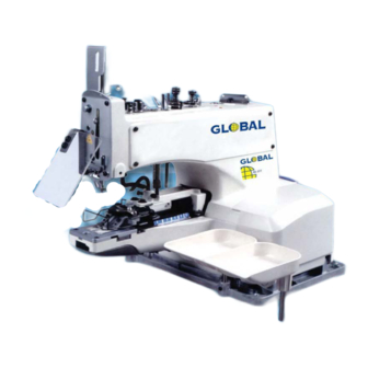
Summary of Contents for Global BS 377
- Page 1 BS 377 Single Thread Chainstitch Button Sewer INSTRUCTION OPERATING MANUAL PARTS MANUAL E-MAIL: WEBSITE: INFO@IMCA.NET WWW.IM CA.NET...
- Page 2 CAUTIONS FOR SAFETY...
- Page 3 IMPORTANT SAFETY INSTRUCTIONS Putting sewing systems into operation is prohibited until it has been ascertained that the sewing 1ystems In which these sewing machinee will be built into, have conformed with the safety regulations in your country. Technlcal service for thoae sewing systems Is also prohibited. Observe the basic safety measures, tnciuding, but not limited to the following ones, whenever you use the machine.
- Page 4 FOR SAFE OPERATI O N 1. To avoid personal Injury, never put your fingers under the needle when you turn ON the power switch or operate the sewing machine. � 2. To avoid personal injury, turn OFF the power switch when you tilt the machine head. 3.
- Page 5 CAUTION BEFORE OPERATION L:!!::i WARNING: To avoid malfunction and damage of the machine, confirm the following. • Use the oil adaptable to the machine specifications. • Clean the sewing machine thoroughly before using it for the first time. • Remove all dust collected on the sewing machine during the transportation. •...
- Page 6 INSTRUCTION MANUAL...
-
Page 7: Table Of Contents
CONTENTS 1. SPECIFICATIONS ......................1 2. PREPARATION OF THE SEWING MACHINE ..............1 2·1. Installation ............................1 2-2. Lubrlcatlon ............................2 2•3. Attaching the needle .......................... 2 2-4. Attaching the needle bar cover ......................3 2-5. Attaching the button tray assembly ....................3 2·6. -
Page 8: Specifications
( 1. SPECIFICATIONS - - - MB- 373 MB- 377 Sewing speed Normal�300 rprn (Max. 1,500 rpm) 8, 16 and 32 stitches Number of stitches Lateral feed 2.5 to 6.5mm Feed amount Lateral feed 2.5 to 6.5mm Longitudinal feed 0. 2.5 to 6.5mm Longitudinal feed o. -
Page 9: Lubrlcatlon
2-2. Lubrication WARNING: To protect against possible personal injury due to abrupt start of the machine, be sure to start the following work after turning the power off and ascertaining that the motor Is at rest. 1) Open the side cover, and apply JUKI New Detrix Oil No. 1 to the portions shown by the red marks f) (f): MB-1377 only). -
Page 10: Attaching The Needle Bar Cover
( 2-4. Attaching the needle bar cover ) WARNING: To protect against possible personal injury due to abrupt start of the machine, be sure to start the following work after turning the power off and ascertaining that the motor is at rest. 1) Loosen screw 8 and remove thread guide 2) Place needle bar guard O under thread guide and attach thread guide... -
Page 11: Adjustment Of The Sawing Machine
ADJUSTMENT OF THE SAWING MACHINE 3-1. Thread tension adjustment Tension post No. 1 O is used to adjust the thread tension to sew on the button and a relatively low tension will be enough. Tension post No. 2 8 is used to adjust the thread tension applied to the root of the button sewing stitches. -
Page 12: Adjusting The Nipper
( 3-4. Adjusting the nipper ) WARNING: To protect against possible personal Injury due to abrupt start of the machine, be sure to start the following work after turning the power off and ascertaining that the motor is at rest. 1) Provide a 0.4 to 0.6 mm clearance between nipper block 8 and nipper O to prevent the nipper O from hold... -
Page 13: 3·7. Position Of The Needle Guide
To protect against possible personal injury due to abrupt start of the machine, be sure to start the following work after turning the power off and ascertaining that the motor is at rest. 3-7. Position of the needle guide) Loosen screw 8 and provide a 0.05 to 0.1 mm dear- WARNING: ance between the needle guide O and the needle �... -
Page 14: 3· 11. Timing Of Thread Tension Release
( 3-11. Timing of thread tension release) Turn the needle driving pulley as you draw the thread in the direc tion of arrow mark and you will find a point at which the tension discs on the tension post No. 2 release the thread. At this moment, the standard distance from the top end of the needle bar bushing (upper) to the top end of the needle bar is 44 to 47 mm (in case of the needle of TO X 7, 54 to 57 mm). -
Page 15: Setting A Number Of S1Itches
3-13. Setting a number of stitches) WARNING: To protect against possible personal injury due to abrupt start of the machine, be sure to start the following work after turning the power off and ascertaining that the motor is at rest. To change the number of stitches, open the left-hand side cover and change the number of strtches using st i tch number adjusting screw O and stitch number adjusting lever 8 (optional). -
Page 16: Automatic Thread Trimmer
( 3-15. Automatic thread trimmer ) (1) Adjusting the position of the moving knife WARNING: To protect against possible personal injury due to abrupt start of the machine, be sure to start the following work after turning the power off and ascertaining that the motor is at rest. When the presser has completely lifted at the stop... -
Page 17: Knot-Tying Mechanisms
3-18. Knot-tying mechanisms) WARNING: To protect against possible personal Injury due to abrupt start of the machine, be sure to start the following work after turning the power off and ascertaining that the motor is at rest. (1) Adjusting the knot-tying connecting plate Loosen screws O and adjust so that a clearance of 1 to 1.5 mm is provided between the needle &... -
Page 18: Changeover Of With/Without Knot-Tying
( 4) Changeover of with/without knot-tying To make "with knot-tying", pull knot-tying changeover knob toward the front and place it to the position in the figure. To make •without knot-tying", pull knot-tying change• over knob toward the front and p l ace it to the position in the figure. -
Page 19: Attachments
4-3. Attachments WARNING: To protect against possible personal injury due to abrupt start of the machine, be sure to start the following work after turning the power off and ascertaining that the motor Is at rest. 1) In order to install the attachment on the machine, you may have to remove button clamp mecha... -
Page 20: Attachments For Shank Buttons (Peart Buttons) (Z033)
(1) Attachments for shank buttons (Peart buttons) (Z033) WARNING: To protect against possible personal injury due to abrupt start of the machine, be sure to start the following work after turning the power off and ascertaining that the motor Is at rest. (INSTALLATION) Remove both the button clamp mechanism assem•... -
Page 21: Attachment For The Second Process Of Wrapped-Around Buttons (Z035)
(3) Attachment for the second process of wrapped-around buttons (2035) WARNING: To protect against possible personal Injury due to abrupt start of the machine, be sure to start the following work after turning the power off and ascertaining that the motor is at rest. (INSTALLATION) (Z035) Remove the button clamp mechanism assembly, but... -
Page 22: Att Achment For Metal Buttons (2038)
(5 ) Attachment for metal buttons (Z038 ) WARNING: To protect against possible personal injury due to abrupt start of the machine, be sure to start the following work after turning the power off and ascertaining that the motor is at rest. (INSTALLATION) Remove both the button clamp mechanism assem... -
Page 23: Troubles And Corrective Measures
® TROUBLES AND CORRECTIVE MEASURES CAUSES CORRECTIVE MEASURES TROUBLES The yoke sl i de does not move in lhe correct 1. Thread breakage A<ljust the timing of forward. backward and way , sideways of the yoke sl i de. The tension lever has been improperly adjusted. Property adjust the tension lever. - Page 24 PARTS MANUAL...
- Page 25 1. BUTI'ON CLAMP MECHANISM COMPONENTS l ____ ____ ____ ____ _ r ____ ____ ____ ___ l t- 0-1s �------------------------...
- Page 26 .'l't . 260-26858 PICl·UP DEVICE ASM. • 400·41068 BUTTON CLAIIP LlrTING HOOl SS-7160940-SP SCREW 15/64·28 L•9 SS·K21413-SP SCR.&11 3/16·32 L-13.5 IIP·0601016·SD WASHER 6XI0.6Xl m 260•%6f>02 BUTTON CWP HOLDER SS•70i0410•SP SCR.&11 9/64•40 L• 3.6 SD·066030l•SP HINGE SCREll D•S. 5 H•3 280-26403 JAI LEVER HOLDER SD-0660181-SP HING£...
- Page 27 2.ARM & MISCELLANEOUS COVERS COMPONENTS 33 3 2 " f 0-22 « �4 20 � �...
- Page 28 ·- -· -· ·-- ..·· - ,. _ I!) __ - � _ . _ . � _!19, ___ . ______ .D.� ; _C_ � _I. P. ! _f.� !f .._,.t_ !'-':f • 400-38'16 fACl_P\.ATE_COMPL. > Sl-4040865-SP SCREW •...
- Page 29 · -·---··· - ·- ·-- - · --·--·- 3. LOOPER SHAFT MECHANISM COMPONENTS ,,..___, � ta �c:: ..__, a L ____________ .J �...
- Page 30 ·-· ·-········· ..J!S!\IY., ... 1J!T!.. ___ r�_"!:) . _. _______ . _o _ � LC.� _l f .T .1.'?.? ..<l!t. CS·07907ZA·TH TIIRUST COLLAR A.SM. CS•0790721 ·TH THRUST COLLAR 0•7 .94 1•7 C I J SCREW 9/64·40 L-6.
- Page 31 4. NIPPER & THREAD TENSION PARTS COMPONENTS...
- Page 32 .. ---- ·-- '!'I!�'!> ..� ___ .. � ."9•. ___ .. _ . ___ o. � � _c _ � _1 _ ,_ _1 . � � _ . _ . -�L Sl-4°'11$5-SP SCREII 116 L-12 400-38205 IIILOLl_JIAJt_GUAIID SD·07tl276·TP SROOLDU SCREW 111·603000l·S"...
- Page 33 5. FEED PLATE COMPONENTS...
- Page 34 ··-··· ·-·-· ..- ·· ·- �;.'!' ... fl'!l!.._ .._o_� f_C_� J.P . ! _l_� �-. _. _fl!L .t�/f� ..ru.n. 12S2t-37S-OOO SJWJ. JUT'To,I SS·tl:IOkl·TP SQU:I l/11-11 L-1 • 110·Z4I04 U, ICU'OI rt II lt.U: I 11G SLOCI 260-14901 CIOSSltlSt ,m lOIClTOa 0t0$$WIU rtD IAJClTOI P'llt...
- Page 35 6. BUTTON CLAMP LIFTER COMPONENTS...
- Page 36 . ·-·-- ·-- ·- - -··- · - �.c.� ·'. ,_ ! _ 1 . � �. _ .. .'I!>:. !17 r. I!>. _ - � .. _ - � - 19- ..__ .. _ - ·. � LtnllG_Ltvtlt 400·Slllt IIISJIIIIG M0-11101...
- Page 37 7. NEEDLE DRIVING PULLEY SHAFT COMPONENTS ' " -�L tl20)•372-000 IALI, ..• ' 260-U«n l'tJU.tt I !IS I.Rt ..,,,.. 400-31203 IWJ._SIWJ . 2'0·11SOO Sf'ltt,.-; 400•l81H DIii YI IIIC PVLl.Cf .LSI. ioti•UJfS iM:ifliC_rOU2t Sl•I040I ll • ff SCIDM L-4 JllJILt . )111 YI 11G ,..N.Ul SILUT .OO•SM<t •...
- Page 38 8. NEEDLE BAR DRIVING MECHANISM COMPONENTS !l!',l!I .. ! -'-� �- .. _"'{t1_ ..t!t. . 'MT.�- - ..-- - � LC.� _I_P_ SS·1080610·TP SCID 1/1·« t.,.4.S 141·08107 Rl!DLI IIOt IIIDI.IW-IJICILOIIIJ 2'0· 11707 4G0•40KI IIUIU_W_IAUIICI w cu. 400-40H2 IIIDI.I www ii 1..:u 11-164 I loo-sf...
- Page 39 9. STOP MOTION MECAHNISM COMPONENTS "" 20 � t' � /1 2� ttO-UIOf STOP a,flOII PLIJIIGU IOt •·-3·SP 111T N TIPU CIIOIS I Ill. lOOl 400-31111 Sl·IOIIIIO• ff SCIII N Loll IUft-372-000-A S'IOP a,f IOI P- LIVDI BJ-BIR 400-31110 S'IOP .117l'IOII.SPIIIIG -•-•000 IUIUI CVAIOI •...
- Page 40 SELECTING PARTS COMPONENTS 10. ST I TCH -- - ..... -- - ,.,., .. D-llt'Utt·ff IPIIN ,_ fllCT* PUii • • •---• ntCTJGI ,un ll'TATI•..,,..--•.u. 1 111., 11'1DIU91NUYD •. ,. ----r- M•JIM hiiiW fQft -- -- fllCT1CIINn ..
- Page 41 11. THREAD BIND NOTCH COMPONENTS (FOR 3 7 7) r---- 1�1 ..� � �� ....''-.] ..1�� j--1 0 � · u --@ k�, � �i �15 � 2 4 � �...
- Page 42 ·-----···- .. · ·- --·� .• L 400·3U88 TIIRW_IUD.Ll'IIR 400 � 62 COUICTIIIG.PU.n.WGl SD· 321-TP SIIOUUIR scan M.35 H•l.1 400·114U COIIIIECIIIG_Pt.t.n_SIW.J. ff·0430800·SD WASHER 1M a .. • 1o4o150.r, SD·0720331• . SP SIIOUUDt SCIEI • D250t·Z12·J.OO -,; C6IP root WJ. Lllll •...
- Page 43 12. THREAD Sl'AND COMPONENTS ------------- -------------- ✓ - �.,,. .,,..,,. • .,,. 0--- -<f· j � .---1 � 14 [.,,.·/ L __________________________________ i...
- Page 44 - �L 280·01'51 T1IU.U STUD ASI. • 221-3 0401 SPOOL 111ST ROD, UPPU 2% 1- 3 0 309 SPOOL UST ROt, LOIIR TIIBU STAB NOUD PLUI 210-0UOO ( I) --ffi- TIIRUJ IIUSIIIG T1lllil GUIDI A 210·0l40t sPOOI. Jolff ifl .. Jiiot •...
- Page 45 13.ACCESSORIE PARTS COMPONENTS r ------------------ j ____________________ � I it &-l • > L ________________________________________ J �,,� U::: 1 " '- / ",/11 c __ t/ '\(��I · 1 r --------L ___ r ---1 r--- --- 7 ---7 2 9 -1 2 7 _.
- Page 46 . Cl!L 121·33303 VllllLCOYU SCUI Ml VII, L.\ltGl Ul·UOOI lffll·IOOll601 IIWLI TQll 111·1 400·41012 IA&I.SCID.SIT -m IIUIID CUSIIIOR 400·38174 D-iJAbo-d R/U-D Loli IIll.612 • IP·Oll20M·SI liJIII J. U•IIIOIIO·IP IIUT 16/'4·11 -ffi- 400-41071 ACQUORII_IWI_ASI. m-mn 11t·»l06 SCIII IRIVD 1IDDLI 1IRUCII UO·UIOI 400·11127 nill.llJPPORT .IWl ( I)
- Page 47 14 .. SPECIAL ORDER SPEC COMPONENTS -� W·201010AO PICl·UP DEYICI ASI. L BUl10N IIOTOR.PIILLll.50BZ_l500RPI.ASI 400·38290 12556-372•0il BUTrOR Cl.Allf JAI LllER ASI .• L 12H3·372·0il 8U1TOII CIJ.IP UI L&nll ASI., R D2556•372•C.V. BUTTOtl CLAIIP JAI LllIR ASI., L D2658·372·cll IOffok CU.ii' JII llftJi Ui . . R D2628-373•COO·A F!!D PLATE.
Need help?
Do you have a question about the BS 377 and is the answer not in the manual?
Questions and answers