
Subscribe to Our Youtube Channel
Related Manuals for Global BS 9917


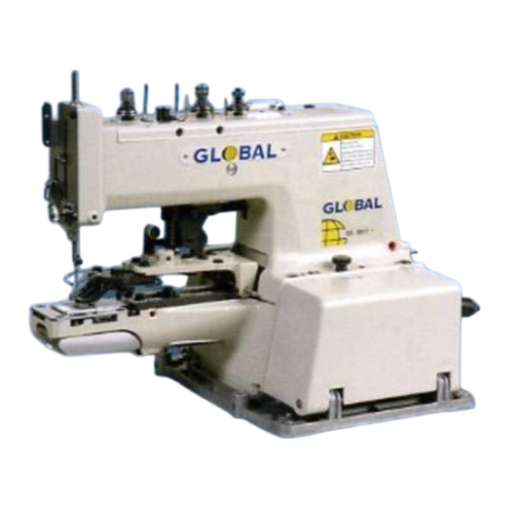
Summary of Contents for Global BS 9917
- Page 1 GLOBAL BS 9917 Instruction & parts Manual www.globalsew.com info@globalsew.com...
-
Page 3: Machine Body
A. Machine body B. Stitch number conversion ----- rrr --- --e• H -- ·' l ___ _ _ .,,, �<@ • ---- �-... - Page 5 A. Machine body Description Ref. No. Bed base assy 8X74510001 Bed base 8X74519000 10 -1 Bed cover ( R) assy BX07738901 10 -2 Bed cover shaft B996126000 10 -3 Set screw, socket (CP) SM5. 95 xlO B096349070 10 -4 BX03115009 Clutch lever assy 10 -5 Clutch driving lever assy...
- Page 6 C. Driving clutch and brake mechanism �1)1 · >• 11-6 11-8 11-9 11-1 O 11-11 11-12 11-13 11-14 ml) jj m llill) ) illl> &>== :: :: :: :::: ,:I :: :: :::: :: :: :: � jm 11-7 16-4 16-3 11-2 11- 3 �...
- Page 7 C. Driving clutch and brake mechanism Ref. No. Description Driving shaft bush ( U 8995895900 Driving shaft bush ( R) BX07732000 8097340398 Set screw, (CP) SM5. 95 BX07731909 Pulley assy 4 -1 Pulley BX76769009 8996118000 Needle bearing 4 -2 BX76760009 Ball holder Screw, SM3.
- Page 8 D. Needle bar and driving clutch mechanism 1-----1-1-3 13 - - - 1( 12�...
- Page 9 D. Needle bar and driving clutch mechanism Description Ref. No. BX07601009 Needle bar driving assy 1 -1 BX07690009 Crank rod assy 1 -1 -1 BX07:l91009 Lower crank rod ( Ll assy 1-1-1-1 B968452009 Screw, M4. 37 1 - 1-1-2 BX07698000 Felt 1 - 1 - 1 - 3 B095330298...
- Page 10 E1. Feed mechanism � -- ··::::-r � � c � 42 � ..--"- . _ __::.., , � � __ __., � 11 � �--, 11 � li-- 67 ' .- .- ------.- I 33...
- Page 11 E1. Feed mechanism Description Ref. No. B995032909 Cam shaft BX07666000 Cam shaft bush ( U Cam shaft bush ( R) B995020000 Set screw, (CP) SM5. 95 B097340398 Worm gear assy B096330488 Set screw, socket (CP) SM6. 35 Transverse feed cam assy B096330488 Set screw, socket (CP) SM6.
- Page 12 E2. Feed mechanism 44 -2 - - -- 44-4 - - -J 44. 3 - For Button Size 44.5 .3 44-1 44• 44 -5 -1 l. � 44 -5• 2 44.5 .10 - - - --" 44 .,3 !&=4417 44.5.4 44.9 �...
- Page 13 E2. Feed mechanism Description Ref. No. < Common parts> Presser arm BX73758001 44 -1 Presser adjusting plate assy BX07651059 44 -2 Washer, plain 6 44-3 BX07415009 Bolt, socket M6 x 10 B092049088 44 -4 Button clamp bracket BX07646909 44 -5 -1 Guide pin B995954009 44 -5 -6...
- Page 14 20-9 20-4 � F. Work clamp lifter mechanism , o � N f , a , 20-s-® � 20-s --{t:'._ • 20-2 �23-2...
-
Page 15: Work Clamp Lifter Mechanism
F. Work clamp lifter mechanism Description Ref. No. Driving cam assy BX07622009 Set screw socket (CP) SM6. 35 8096330488 1 -1 Button clamp driving fork BX07621909 Button clamp driving fork shaft 8995984009 Set screw, socket SM5. 95 8096340488 Set screw collar assy BX07410009 Set screw. - Page 16 G. Lower shaft __ ___::_ :_:' ' mechanism H. Loop spreading mech anism...
-
Page 17: Lower Shaft Mechanism
G. Lower shaft mechanism Ref. No. Description BX07588009 Helical gear assy 1 -1 8096330488 Set screw, socket (CP) SM6. 35 BX07587909 Lower shaft BX07586000 Lower shaft bush, F BX07585000 Lower shaft bush, 8 BX07584009 Lower shaft gear assy 5 -1 B096330488 Set screw, socket (CP) SM6. -
Page 18: Threading Mechanism
J. Threading mechanism --12-1... - Page 19 J. Threading mechanism Description Ref. No. Top cover assy BX07495901 Top cover 1 -1 BX07572901 Slider assy, B 1 -2 BX07494909 M4. 76 Shoulder screw. 1 -3 BX07560009 Rotor base BX07569009 1 -4 Rotor assy 1 -5 BX07568009 Screw, pan SM4. 76 -32 x6 B048390498 1 -6 Washer, plain 5...
- Page 20 • er mechanism K. Threading trim_m __ _...
- Page 21 K. Threading trimmer mechanism Ref. No. Description BX73741009 Thread trimmer lever assy 1 -1 BXF9024009 Thread trimmer lever sub assy 1 -1 -1 BX74493009 Thread trimmer lever 1 - 1 -2 BX07604909 Claw 1 -1 - 3 BX07603009 Roller 1 - 1 - 4 BX07602009 Shoulder screw 1 - 1 -5...
- Page 22 L2. Option parts...
- Page 23 L2. Option parts Description Ref. No. < For button size 010 - 020> Button clamp set A BX07309009 BX70095909 Button clamp assy 2 -1 Button clamp bracket 2 -1 -1 BX07646909 BX81112009 Button clamp, L 2 -1 -2 2 -1 -3 BX70009009 Spring, plate;...
- Page 24 L3 0 • pt1on parts • • 5-1-7 5-1 -13 5-1-1 O � ½i 'it - - 5 _ , _ , , 5 -1- 9 5- ,-• ---<i!!, � 5- 1- 5- 1- 8 L . � 5-3----, � 5-1-1 5-11 5-10...
- Page 25 L3. Option parts Ref. No. Description Sharik button attachment 8968530901 B968421701 Shank button clamp brae. assy 5 -1 Shank button clamp bracket 5 -1 -1 B956426001 5 - 1 - 2 Button clamp, A B968433909 Button clamp, B 5 -1 -3 B968432909 5 -1 -4 8048430298...
- Page 26 L4 0 pt1on parts �"'�· · -1-1-1 ·1-1-2...
- Page 28 L5. Option parts 8-4 - - , � 8- 3 �9-6 9-4.- __J� 11-2-2 9-3� �...
- Page 29 L5. Option parts Description Ref. No. Label attachment BX07418009 Label clamp BX01966009 Stopper BX01967009 Clamp spring BX01965009 Screw, SM2. 38 x3. 5 BX09815009 Stay button attachment (SI BX07417009 Stay button feed plate BX01628009 9 -1 Button receiver ( D) BX01627009 Button receiver ( U} BX01626009 Screw, SM3.18-44x3.4...
-
Page 31: Option Parts
L6. Option parts Ref. No. Description BX07475909 Snap clamp set 4 -1 BX07474909 Snap clamp assy 4 -1 -1 BX07646909 Button clamp bracket 4 -1 -2 8992569009 Snap clamp, L 4 -1 -3 8992571009 Snap clamp, R 4 -1 -4 8995954009 Guide pin 4 -1 -5... - Page 32 Z1. Accessories 1--9 � Q2)--10 fEil �--- --�- JI,. 7-1-3 __ LI_ I �---, < > For Export ::.. - 1=--=- - -::... - - -----... 2 4 -3 J_ - 24-1 0{:J24-4I : 40 CJL..:) '-- - ---- - - - - \...
- Page 33 Z1. Accessories Description Ref. No. B988119009 Accessory bag 2 -1 B905766009 Screw driver, 2. 6 x70 B992273009 Screw driver, 3. 4 x70 B903320009 Wrench, 10 x 12 3 -1 3 -2 B968805009 Wrench, 7 x8 B968389009 Hexagonal wrench, B968008009 Hexagonal wrench, B992046009 Hexagonal wrench, 4 B995057096...
- Page 34 Z2. Accessories �101 @- 2 6...
- Page 35 Z2. Accessories Ref. No. Description 7 -2 BX09407001 Treadle assy (For Z - type stand) 7 - 2 - 1 BX09911007 Treadle pedal 7 - 2 -2 B977922009 Treadle shaft 7 -2 -3 B991303007 Bracket 7 - 2 - 4 B991302001 Collar 7 -2 -5...
- Page 36 Different parts list G -9 E1 - 7 E1 -5 E1 -6 Vertical feed Worm gear Transverse Stitch control Worm assy feed cam assy cam assy cam assy assy � BX07582-009 BX07664-009 BX07659-009 BX7 4414-009 BX07665-009 ® BX07663-009 ® BX07664-009 BX07658-009 �...
- Page 37 Index Code Ref. No. Code Ref. No. Page Page Code Ref. No. Page Code Ref. No. Page 5 - 1 B085070878 24 -4 8097390598 5 -1 -5 B995012009 B908303007 B085040878 20-5 6 - 1 - 1 - 5 8995011009 B097390398 1 -4 B995909009 B905037009...
- Page 38 Index Code Ref. No. Page Ref. No. Page Ref. No. Ref. No. Page Code Code Page Code BX07502009 I 12 BX07691009 2 -1 B980110009 B950554009 BX07501009 9 6-1-1-13 44 -12 BX07680009 3 BX0759800S 1 -16 BX07689009 5 8X0759400S 20 -1 B988119009 1 B959059809 BX07687009 6...
- Page 39 Index ---�- Code Rei. i\Jo. Page Ref. No. Code Ref. No . Paqe Code Code Ref. No. Page �� BX7449 1 W09 11 -1 BX07 484009 6 BX01610009 11 -2 -2 BX7449:S009 BX07483009 7 11 --2 -3 8X01619009 BX74488009 BX07482009 8 11-2-•4 BX01618009 BX7t14860093...
-
Page 40: Safety Instructions
Thank you very rnuch for buying a our cornpo11y • sewing machine. Before using your new machine, please ,ead the safety instructions below and the explanations given in the instruction manual. With industrial sewing, it is normal to carry out work while positioned directly in front of moving parts such as the needle and :'lreac take -up lever, and consequently there is always a danger of injury that can be caused by these parts. -
Page 43: Warning Labels
3. Warning labels The following warning labels ap· p ear on the sewing machine. or are Please follow the instructions on the labels at all times when using the machine. If the labels have been removed diffcul to read, please contact your nearest Brother dealer. 1 Safety devices: (A) Finger guard ( B) Eye guard... -
Page 49: Ground Wire Connections
5 -5. Ground Wire Connections Connect the ground wire to the sewing machine head and mo- tor. ( Use the correct type of ground wire. ) 1. Secure the ground wire ( 1 ) to the sewing machine head with screw(2). -
Page 50: Turning The Machine Pulley By Hand
6. TEST CJPERATION ..-------------------------------------- - ------- ACAUTION not touch any the moving parts nress any objects against machine while sewing, a:; this may r<'511lt £:\personal injury or damage lo the mach11, 1. Insert the power cord plug into a wall outlet, and turn on the power switch. -
Page 51: Installing The Needle
8. PREP1- \ RATION BEFORE SEWING 8 -1, Installing the needle A.CAUTION Turn off the power switch before installing the needle. The machine may operate if the pedal is pressed b y mistake , which could result in injury. L::!!:A The motor will keep turning even after the power is switched off as a result of the motor·... - Page 52 8 -2. Threading CAUTION Turn off the power switch before threading. The machine may operate if the pedal is pressed by mistake, which could [:!!1 result in injury. The motor will keep turning even after the power is switched off as a result of the motor's inertia. Wait until the motor stops fully before starting work.
-
Page 53: Adjusting The Thread Take - Up Lever
8 -3. Adjusting the thread take - up lever �---------------------------------------·-·-·-------� A,.CAUTION Turn off the power switch before adjusting the thread take - up lever. The machine may operate if the pedal is pressed by mistake, which could result in injury. The motor will keep turning even after the power is switched off as a result of the motor's inertia. -
Page 54: Vertical Feed And Transverse Feed Positioning
<Transverse feed> 8 -4. Vertical feed and transverse feed positioning A,CAUTION Turn off the power switch before carrying out vertical feed and transverse feed positioning. The machine may operate if the pedal is pressed by mistake, which could result in injury. /.::!l. -
Page 56: Setting The Number Of Stitches
8 -6. Setting the number of stitches CAUTION Turn off the power switch before setting the number of stitches. The machine may operate if the pedal is pressed by [::!1 mistake, which could result in injury. The motor will keep turning even after the power is switched off as a result of the motor' s inertia. Wait until the motor stops fully before starting work. -
Page 57: Checking The Needle Drop Position
9. SEWING .A.CAUTION £:\ Attach all safety devices before using the sewing machine. When turning the machine pulley by hand in order to l,:J:!:A If the machine is used without these devices attached, check the needle down position in the hole of the injury may result. -
Page 61: Adjusting The Needle Bar Height
12. STANDARD ADJUSTIV1Ef\ J TS ----------------------,., A.CAUTION I('\ Maintenance and inspecti �� of the _ s�w ing machine should When turning the ma � hine pull � y by h �� d, turn thE � pulley until the needle Is at the final posItIon after orn \Y only be carry out by a qualified technician cycle. -
Page 62: Adjusting The Needle Guide
Adjusting the needle and looper clearanc• 3 Adjusting so that the clearance between the needle and the tip of the looper (1) is 0. 03 -0. 08mm when the needl.:- bar rises from its lowest position until the tip of the looper ( 1 ) is aligned with the center of the needle. -
Page 63: Adjusting The Machine Pulley Clearance In The Direction Of Thrust
12 -6. Adjusting the machine pulley clearance in the direction of thrust At the sewing machine stopping position, adjust the clearance between the machine pulley ( 1 I and the clutch plate ( 2) to 0.5-0.Smm. 1 . Loosen the nut ( 3 l, and then turn the set screw ( 41 to adjust the postion fo the ball presser plate ( 5 I . -
Page 64: Adjusting The Button Opener
12 -9. Adjusting the button opener Carry out the following adjustment after carrying out the ad justment in "Adjusting the button clamp lift amount". < Transverse position> Contact Adjust so that button opener claw B (3) touches the button opener claw (4) at the same time as the presser lifter arm ( 1 l touches the roller ( 2) when the machine pulley is turned to move the mechanism to the final stitch position. - Page 66 13. REPLACING PARTS ACAUTION 1---------------------------------------------- Replacement of parts should only be carried out by a qualified technician. Turn off the power switch and disconnect the power cord before installing any optional parts. The machine may operate if the pedal is pressed by mistake, which could result in injury. The motor will keep turning even sfter the power is switched off as a result of the motor's inertia.
- Page 67 1. Loosen the two bolts ( 1 ) . and then remove the feed plate (2) that is currently installed. 2. Provisionally install the new feed plate (3) with the two bolts ( 1 l. 3. Loosen the shoulder screw (4), push the size adjust plate (5) as far as it will go, and then tigl1ten the shoulder screw (4).
-
Page 68: Troubleshooting
14. TROUBLESHOOTING • Pl&ase check the following points before calling for repairs or service. • If the following suggestions do not solve the problem, turn off the machine power supply and contact your neares, servicE center. A.CAUTION Turn off the power switch and disconnect the power cord before carrying out troubleshooting. �... - Page 69 Possible cause Proble 4. Thread breaks • Is the needle and looper timing correct? • Thread frays and breaks. Adjust the height of the needle bar. • Thread breaks at different points. Adjust the needle and looper timing. • Thread breaks and stitch skips •...
- Page 70 Possible cause Proble 9. Stitch joint is loose. • Is the thread take - up amount for the thread take up lever too small? Adjust the position of the thread take - up lever in accor dance with the thread being used. •...
- Page 71 Possible cause Proble 13. Thread winds onto looper in ma • Is the auxiliary tension too weak? chine stop position. Adjust the auxiliary tension. • Set the needle drop position to the outside of the button thread hole. • Is the thread being used too thick? Use a finer thread.
- Page 72 Proble Possible cause • Does the outer diameter of the button match the opening amount for the 18. Button does not drop at the stop button clamp? position. Set a button in place and adjust the size adjust plate. • Is the button opener adjusted correctly? Adjust the transverse position and vertical position of the button opener.
Need help?
Do you have a question about the BS 9917 and is the answer not in the manual?
Questions and answers