
Subscribe to Our Youtube Channel
Related Manuals for Unilumin UMini W


Summary of Contents for Unilumin UMini W
- Page 1 Revision Records Version Revised Content Date Initial release 2023.04.18 The manual may be modified without any prior notice.
- Page 2 Revision Records Versio Revised Cpntent Date Initial release 2022.10.14 SPEC update 2023.04.14 Cabinet drawing 2023.05.05 update SPEC update 2023.07.10 SPEC update 2023.10.18 The manual may be modified without any prior notice.
- Page 3 Copyright The manual is the property of Unilumin Group Co., Ltd. The Unilumin LED’s operating software is developed based on the Windows operating system. No part of the manual can be transcripted, transmitted, reproduced, translated, edited, published, stored to a retrieval system, or used in any form by any individual or organization without a prior written permission of Unilumin.
- Page 4 Read the following content carefully to ensure correct use of the LED display products: WARNING! The LED display may be damaged and become irreparable if you ignore the following warnings. Do not place the LED display upside down or throw it during transport and storage. Do not incline, scratch, or crash the LED display during installation.
-
Page 5: Table Of Contents
Contents Chapter 1 Product Introduction ....................7 Features ..........................7 Cabinet Appearance ......................8 1.3 Specification ...........................9 1.4 System Solution .......................... 10 1.5 Scope of Application ........................10 Chapter 2 Installation and Wiring ................... 11 2.1 Out-of-Box Inspection ........................ 11 2.2 General Installation ........................11 2.2.1 Installation of Fixed LED Display-Front Installation (Standard) ........ - Page 6 3.5.1 Setting Coefficients for a New Receiving Card .............. 31 3.5.2 Setting Coefficients for a New Module ................34 3.6 Pre-storing Picture ........................36 3.7Drying Mode ..........................37 3.8 MDC Mode ..........................39 3.8.1 MDC-Loading ........................39 3.9 Image Booster Engine ....................... 39 Chapter 4 LED Display Playing Setting ................
- Page 7 6.1.2 Incomplete Picture or Incorrect Position of Picture Displayed ........62 6.1.3 Screen Blinking ........................62 6.1.4 Blinking of a Cabinet in the Display .................. 63 6.1.5 Failure in Lighting up of a Cabinet in the Display ............63 6.1.6 Failure in Lighting up Part of the Modules in the Cabinet ..........63 6.2 Replacement of Main Components ..................
-
Page 8: Chapter 1 Product Introduction
Chapter 1 Product Introduction UMini W series is the company's new generation of Mini products. It is based on the concept of high- definition display application and adopts standard 16:9 picture ratio design, and has achieved perfect match between video signals and display terminals. Ultra-thin cabinet design, small space occupation, easy installation, suitable for more scenarios. -
Page 9: Cabinet Appearance
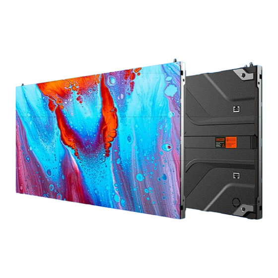
1.2 Cabinet Appearance 1. Screws of upper and lower cabinets. 2. Location pin 3. Signal port on the back of the cabinet 4. Product sticker 5. Working status indicator 6. Cabinet installation hole 7. Signal In/Out 8. Signal In/Out 9. Power In 10.... -
Page 10: Specification
1.3 Specification Parameter Pixel composition 1R1G1B LED type Fully flip chip COB Pixel per Cabinet(dots) 640×360 480×270 384×216 320×180 Cabinet size(mm) 600(W)×337.5(H)×29.8(D) Aspect Ratio 16:9 16:9 16:9 16:9 Physical Material Die-cast Aluminum Parameter 4kg/panel Weight(kg) Refresh rate(Hz) 3840 Frame frequency(Hz) 50/60 Sign cable≤100m,Multi-mode optical fiber≤... -
Page 11: System Solution
Fig 1-2 System Topology 1.5 Scope of Application The UMini W series products can be assembled seamlessly into a screen of any size, and are extensively used as and other fixed LED displays for advertisements in public places such as Conference room, command, control room fields. -
Page 12: Chapter 2 Installation And Wiring
2.2 General Installation Screen calibration is performed on the UMini W series product before shipment, and the product needs to be installed sequentially according to the cabinet number, as shown in Figure 2-1:... -
Page 13: Installation Of Fixed Led Display-Front Installation (Standard)
2.2.1 Installation of Fixed LED Display-Front Installation (Standard) Check whether the bottom beam is level. Make sure that its levelness is within ±1mm. (bottom beam is a must have) Install the cabinets sequentially from bottom to top and from middle to both sides. In addition, in front of the screen, fix the front connecting plates and cabinets with installation screws to the square tubes. - Page 14 Fig 2-4 Front Connecting Plate Fig 2-5 M8×65 socket head cap bolts(front) M8×65 Inner hexagon bolt Front mounting plate Fig 2-6 Back view of front maintenance Installation Details...
-
Page 15: Installation Of Fixed Led Display-Rear Installation(Optional)
Front Mounting plate Bolts Square tube Fig 2-7 Back view of front maintenance Installation Fig 2-8 Front View of Cabinet Installation Fig 2-9 Front View of the Display 2.2.2 Installation of Fixed LED Display-Rear Installation(Optional) Check whether the bottom beam is level. Make sure that its levelness is within ±1mm. (bottom beam is a must have) Install the cabinets sequentially from bottom to top and from middle to both sides. - Page 16 behind the screen, fix the rear connecting plates and cabinets with installation screws to the square tubes. Keep proper joints and flatness between the cabinets during cabinet installation. After the installation of the cabinet is completed, behind the screen, connect the power cable and the signal cable between the cabinets.
- Page 17 Fig 2-12 Rear maintenance installation plate Fig 2-13 Rear installation M10×60 Inner hexagon bolt M10×60 Inner hexagon bolt Rear mounting plate Fig 2-14 Back view of rear maintenance Installation Details Square tube: 40*40mm Rear mounting plate Fig 2-15 Rear View of Cabinet Installation...
- Page 18 Fig 2-16 Front View of the Cabinet Installation Fig 2-17 Front View of the Display...
-
Page 19: Concave Installation (2°~3°)
2.2.3 Concave Installation (2°~3°) Make sure that the bottom beam is horizontal, and the levelness value is within ± 1mm; Assemble the specific trimming cabinet from the bottom to the top and from the middle to both sides successively. Fix the angle block to right side of the the cabinet by using screw KM2*6; (bottom beam is a must have) The left and right cabinets are fixed with left and right shoulder screw, and the mounting plate and cabinets are fixed on the square pipe with hexagon socket bolts. - Page 20 Fig 2-19 Splicing of left and right cabinet Fig 2-20 Splicing of left and right cabinets completed Fig 2-21 Rear Mounting Plate...
-
Page 21: Module Flatness Adjustment
2.3 Module Flatness Adjustment 2.3.1 Module Flatness Adjustment When there is a deviation in flatness between adjacent modules, use the adjustment tool to adjust the magnet forward until the module is flush on the cabinet. For the module at the low end, adjust the adjustable magnet with the adjacent module. -
Page 22: Wiring For Led Display
Fig 2-25 Schematic diagram of module flatness adjustment 2.4 Wiring for LED Display 2.4.1 Common Cables Power Cables DVI Cable Incoming Signal Cable USB Cable... -
Page 23: Signal Cable Connection
2.4.2 Signal Cable Connection Signal cables shall be connected based on the wiring diagram of the delivered products for the project. Sending Box Fig 2-26 Signal Cable Connection Diagram of UMini W1.2 2.4.3 Power Cable Connection Power cables shall be connected based on the wiring diagram of the delivered products for the project. AC Power Cable Fig 2-27 Power Cable Connection Diagram of UMini W1.2... -
Page 24: Smart Control Distribution Box
2.4.4 Smart Control Distribution Box The Smart Control Distribution Box can be used for distributing electric power to the LED display, and has the function for real-time monitoring of the temperature, humidity, smoke, and mains voltage of the external environment. The control software has the scheduled start/stop function, allowing you to set any time for the LED display to be remotely started or stopped Fig 2-28 Internal Structure of Distribution Box... -
Page 25: Chapter 3 Led Display Control Setting
The PLC communication system is RS485, It uses converter from control computer RS232 to RS485. For more detail information, please refer to our Intelligent Power Distribution Management System Manual. Fig 2-29 Distribution Box PLC Connection Diagram Chapter 3 LED Display Control Setting 3.1 Power-on Testing Before performing control setting on the LED display, confirm that each device is connected correctly. -
Page 26: Preparation For Debugging
ground wire of the AC power supply, in order to ensure they are not conductive with each other. The ground wire must be in reliable contact with the ground, and kept away properly from the live wire. The connected power supply shall be distant from high-power equipment. When the 3-phase and 5-wire system is adopted, the load shall be distributed evenly among the phases to ensure three-phase balance as far as possible. -
Page 27: Display Configuration
3.3 Display Configuration Run UniLCT-Mars. Make sure that Control System on the main window is 1. Click the User option and select Advanced Login, as shown in Figure 3-3. Fig 3-3 Main Window of UniLCT-Mars Enter the initial password “admin”, as shown in Figure 3-4, to go to the advanced user window. Fig 3-4 User Login After login, click Screen Config on the main window, as shown in Figure 3-5: Fig 3-5 Main Window for Advanced User... - Page 28 The following window is displayed. Set Sending Board Resolution (1920×1080 recommended). Set Graphics Output Resolution to the same value as Sending Board Resolution. Then click Save to save the settings. Fig 3-7 Sending Board Configuration After configuring the parameters on the Sending Board page, click Recaiving Card to display the following window: 1)...
- Page 29 Fig 3-8 Scan Board Configuration After configuring the parameters on the Scan Board page, click Screen Connection to display the following window: Fig 3-9 Screen Connection Click Read File to load the file xxxx.scr stored in the optical disk, as shown in Figure 3-10.
-
Page 30: Brightness Adjustment
Click Send to HW. After sending, confirm that the screen is complete. Then click Save. Fig 3-10 Screen Connection with Loaded File 3.4 Brightness Adjustment On the main window, click Brightness, as shown in Figure 3-11, to display the brightness adjustment interface: Fig 3-11 Main Window for Advanced User There are four brightness adjustment modes, namely Manual, Schedule, Auto, and Auto Adjustment by Hardware. -
Page 31: Correction Coefficient Management
Fig 3-12 Manual Adjustment Display Quality: Includes Soft mode and Enhanced mode. The Soft mode is generally used for indoor LED displays while the Enhanced mode is used for outdoor LED displays. Gamma Adjustment: Includes Mode A and Mode B. The LED display in Mode A can light up earlier than that in Mode B. -
Page 32: Setting Coefficients For A New Receiving Card
Configure Enable/Disable Calibration to Brightness, click Save, and then click Manage Coefficients to display the following window: Fig 3-14 Manage Coefficients Upload coefficients: Upload the correction coefficient database generated by the software or read back by the display screen to the screen. Save coefficients to database: Read back and save the coefficients from the screen to the coefficient database. - Page 33 Fig 3-15 Selecting Area for New Receiving Card Select the coefficient source. Click Browse at Select Database. Fig 3-16 Obtaining Correction Coefficients for Receiving Card...
- Page 34 Select the corresponding correction coefficients: Fig 3-17 Selecting Correction Coefficients for Receiving Card Select Stable Upload and click Next: Fig 3-18 Uploading Correction Coefficients Adjust Coefficient: Perform a simple adjustment if the displaying effect is not good enough after you upload the coefficient.
-
Page 35: Setting Coefficients For A New Module
Fig 3-19 Simple Adjustment Red:Adjust the red brightness value of calibration coefficients. Green:Adjust the green brightness value of calibration coefficients. Blue:Adjust the blue brightness value of calibration coefficients. 5) Save Coefficients: Click Save to save the correction coefficients to the hardware. The saved coefficients are retentive even after a power failure. - Page 36 where the new module is located. Double click the selected position: Fig 3-21 Selecting Cabinet for the New Module ) Choose Display Mode to Modules. Select the position of the new module and click Next. Fig 3-22 Selecting Position of New Module Module Size:Set the size of the module in a cabinet.
-
Page 37: Pre-Storing Picture
Fig 3-23 Obtaining Correction Coefficients for a New Module 3.6 Pre-storing Picture On the Prestore Picture interface, you can save a picture as the prestored picture for the screen. This prestored picture can be set as a screen displayed upon booting, signal cable disconnection, or DVI signal absence. On the main window, click Tool and select Prestore Picture, as shown in Figure 3-24. -
Page 38: Drying Mode
Fig 3-25 Prestore Picture Settings Prestore Picture Settings Select Picture: Click Browse to select the directory of the picture. Screen Effect: Set the selected picture to be displayed on the whole screen by means of stretching, tiling, or centering. Cabinet Effect: Set the selected picture to be displayed on each cabinet of the screen by means of stretching, tiling, or centering (the number of pictures displayed by each cabinet shall be equal to the number of receiving cards in the cabinet). - Page 39 Fig 3-26 Drying mode Settings Click “drying mode” based on actual circumstances, then click “Refresh” to enter corresponding drying mode. Fig 3-27 Drying mode Settings There are three dehumidification mode levels. The dehumidification time varies with the dehumidification level. Exit the dehumidification mode and select the normal mode. The default brightness value is 60% after you exit the dehumidification mode.
-
Page 40: Mdc Mode
3.8 MDC Mode 3.8.1 MDC-Loading In the main window, tap Tools –Controller Cabinet Configuration File Import(E) to enter the page for importing configuration file to the controller. Select the configuration file that you want to import to the controller and click Add Configuration File. Fig 3-27 MDC Loading Settings Refresh Configuration File allows you to view whether the configuration file is saved to the device in real time. - Page 41 In the main window, tap “Image Booster Engine” to enter into the page Fig 3-29 Image Booster Engine Settings Select the COM Port and Screen to be calibrated, open 22bit, adjust the gray level of the display to 15 gray level, and check whether the screen shake.
-
Page 42: Chapter 4 Led Display Playing Setting
level, and check again whether there is any jitter in the screen body. Jitter indicates that the image quality engine is started to set the image quality. Fig 3-32 Image Booster Engine Settings Fig 3-33 Image Booster Engine Settings Chapter 4 LED Display Playing Setting 4.1 LED Display Playing Setting 4.1.1 Selecting a Playing Solution The playing software UniStudio has three playing modes, namely Simple playing program, Professional playing... -
Page 43: Playing Setting
Fig 4-1 Switching Schedule Mode Fig 4-2 Edit Mode Setting 4.2 Playing Setting 4.2.1 Display Window Setting Run the UniStudio, click Settings and select Display Setting, as in following fig:... - Page 44 Fig 4-3 Display Window Setting Number of Display Windows: Indicates the number of display windows. To increase or decrease the number of display windows, re-enter the number of display windows in the box next to Number of Display Windows and then click Update.
-
Page 45: Editing Professional Playing Solution
Fig 4-4 Startup Setting Auto Run after Power-on: If you enable this function, UniStudio will run automatically the next time when the PC is started. Restart Software on Time: If you enable this function, set the restart interval and time, and click OK, UniStudio will be automatically restarted after the PC time reaches the preset restart time. - Page 46 Fig 4-5 Creating a Playing Solution...
-
Page 47: Editing The Program Page
Editing the properties of the playing solution After adding a general time segment or interstitial segment, click General Segment 1 to edit the properties displayed in the segment editing area on the right side, as shown in Fig 4-6: Fig 4-6 Properties of General Time Segment 4.3.2 Editing the Program Page Creating a program page As shown in Fig 4-7, right click General Segment or click the Add Global Program Page in the toolbar to... - Page 48 Setting the properties After creating the program page, click Program 1 and set the background, displaying mode, and other properties displayed on the property page on the right side. See Fig 4-8: Fig 4-8 Properties of Program Page If you select Specify Number of Times, the next general program page is played after the preset Times to Play for the display window with the longest playing time on the current program page has been reached.
-
Page 49: Editing The Display Window
When the current program page is played, the background picture or colour of the program page is displayed in the area not covered by the display window, as shown in Figure 4-9: Fig 4-9 Background of Program Page After adding the program page, you can move, copy, paste, or delete the program page by using the toolbar in the program page editing area, or by using the short-cut menu, as shown in Fig 4-10. - Page 50 After adding a program page, you need to add a display window to this program page. Click Add Window on the toolbar of the program page to add a window to the current program page. See Fig 4-11: Fig 4-11 Adding a Window to Program Page After the window is added, the added window is selected and displayed on the screen, as shown in Fig 4-12: Fig 4-12 Added Window Setting the location and size of the display window...
- Page 51 Fig 4-13 Setting the Window Size Click the display window on the screen and adjust its size by using the mouse, as shown in Fig 4-14: Fig 4-14 Adjusting the Window Size Using the Mouse c) Deleting a display window Select the window to be deleted.
-
Page 52: Editing The Media
Fig 4-16 Moving a Display Window 4.3.4 Editing the Media Adding the media The type of window for adding the media is Common Window. Click the Add Media button of a common window to select media of different types to be added into the media list. See Fig 4-17: Fig 4-17 Adding the Media After adding the media, you can set the media texts and properties, as shown in Figure 4-18. - Page 53 Fig 4-18 Media Setting Window Setting the media properties Different media have different properties. After a medium in the media list is selected, the property page of this medium is displayed below the selected medium. On this property page, you can change the properties of the medium. See Fig 4-19: Fig 4-19 Properties of Medium Editing the media in the common windo...
- Page 54 Modify Fig 4-20 Changing the Media Playing Times Right click the media to perform operations on the selected media, as shown in Fig 4-21: Fig 4-21 Media Operation Menu Right click a blank area in the media playlist. A media playing menu is displayed, as shown in Fig 4-22:...
-
Page 55: Playing The Media
Fig 4-22 Media Playing Menu 4.3.5 Playing the Media After the playing mode is edited or loaded, click the play key on the main toolbar to start the current playing mode, as shown in Fig 4-23: Fig 4-23 Play Key on the Toolbar After play is activated, the editing page is switched to the playing page, as shown in Fig 4-24:... - Page 56 Fig 4-24 Play Information Page Clicking Pause or Stop on the toolbar can pause or stop the currently played program. You can also perform this operation by using the operation menu that appears when you right click the display window. See Fig 4-25: Fig 4-25 Short-cut Menu Attention: All display windows on the same program page plays simultaneously.
-
Page 57: Saving And Opening A Playing Solution
Fig 4-26 Transparent Displaying Effect of the Clock 4.4 Saving and Opening a Playing Solution Save: After a playing solution is created, you can click Schedule on the toolbar and select Save or Save As to save the playing solution in the format of xxxx.plym. See Fig 4-27: Fig 4-27 Saving a Playing Solution File Open: After a playing solution is saved, you can directly click Schedule in the toolbar and select Open to open the playing solution. -
Page 58: Chapter 5 Startup, Shutdown, And Maintenance
Fig 4-28 Opening a Playing Solution File Chapter 5 Startup, Shutdown, and Maintenance 5.1 Startup Sequence Start the distribution box for the LED display. Start the control computer. Start the video processor. -
Page 59: Shutdown Sequence
Start the sending box. 5.2 Shutdown Sequence Shut down the video processor. Shut down the sending box. Shut down the control PC. Shut down the distribution box for the LED display. 5.3 Daily Maintenance Check whether ambient temperature and humidity meet the operating conditions for the LED display on a daily basis. -
Page 60: Warm-Up Operation
5.4 Warm-up Operation If the LED display has been idle for 14 days, perform warm-up operations before using the LED display. Set the prestored picture as follows when you initially start the LED display. This setting is for warm-up operation only. -
Page 61: Ageing Operation
5.4.2 Ageing Operation On the main window, click Brightness to enter the brightness adjustment interface, as shown in Fig 5-2: Figure 5-2 Main Window for Advanced User Select Manual and set the brightness to 26 (the brightness is about 10%) by dragging the scroll bar below Brightness Adjustment. - Page 62 Fig 5-5 Display Control Adjust the screen brightness and perform ageing based on the steps described in Section 5.4.2. Display Brightness Aging Time 2.5h 100% 0.5h...
-
Page 63: Chapter 6 Troubleshooting And Component Replacement
Chapter 6 Troubleshooting and Component Replacement 6.1 Common Faults and Troubleshooting Methods 6.1.1 Failure in Lighting up the Display Causes: No power is supplied to the display or the control devices. The LED display does not have input signals. The control PC is in sleep mode or the graphics card is set incorrectly. Troubleshooting method: Check AC power input of the display and the control devices. -
Page 64: Blinking Of A Cabinet In The Display
The ports on the sending box are loose, or the signal cables are too long. The output resolution of the playing device or sending box is set incorrectly. Troubleshooting method: Check whether the DVI cable and signal cable are connected to the display and devices, or whether the length of signal cables exceeds the maximum transmission distance (the effective transmission distance shall not exceed 10 m for DVI cable, 100 m for signal cable, 300 m for multi-mode optical fiber, and 15 km for single-mode optical fiber). -
Page 65: Replacement Of Main Components
6.2 Replacement of Main Components Before performing maintenance on the LED display, cut off the power supply to ensure your personal safety and equipment safety. 6.2.1 Replacement of Module Cut off the power supply of the display , replace a module of the LED display based on the following steps: Front maintenance Picture Description... -
Page 66: Replacement Of Power Supply
6.2.2 Replacement of Power Supply Cut off the power supply of the display , replace a power supply of the LED display based on the following steps: Front maintenance step Picture Description Find the faulty cabinet Step 1 and disconnect the power supply Remove module and Step 2... - Page 67 Front maintenance step Picture Description Find the faulty cabinet Step 1 and disconnect the power supply Remove the module of Step 2 the fault cabinet Step 3 Remove HUB card Remove the failure Step 4 receiving card and replace it...
-
Page 68: Replacement Of Hub Card
6.2.4 Replacement of HUB Card Cut off the power supply of the display , replace HUB card of the LED display based on the following steps: Front maintenance step Picture Description Find the faulty cabinet Step 1 and disconnect the power supply Remove the module of Step 2... -
Page 69: Chapter 7 Packaging Transportation And Storage
Chapter 7 Packaging Transportation and Storage 7.1 Packaging The UMini W series products would be packed in carton, and the carton is vacuum-packed in an anti-static bag, and finally packed in heavy-duty carton, as shown below: Figure 7-1 Package in Carton Figure 7-2 Package in Heavy-Duty Carton 7.2 Transportation... -
Page 70: Chapter 8 After-Sales And Warranty
Provide On-site Engineer Service for Quality Issues: If there is a quality issue as stipulated in Article 5 of this Warranty Policy, and Unilumin believes the condition is necessary, on-site engineer service free of charge will be provided. In this case, customer shall provide a fault report to Unilumin for on-site service application. -
Page 71: Disclaimer
8.4 Disclaimer No warranty liability shall be assumed by Unilumin for defects or damages due to the following conditions: Unless written agreed otherwise, this Warranty Policy does not apply to consumables, including but not limited to connectors, networks, fiber optic cables, cables, power cables, signal cables, aviation connectors, and other wire and connections. -
Page 72: Other
Shall provide receipt postal information (company name, address, consignee, contact information, etc.) To avoid damages of the returned products during transportation, please be cautious about the package and protection of the products. Unilumin is not responsible for any damages to the returned products or parts during delivery. -
Page 73: Product Warranty Card
8.7 Product Warranty Card Product Warranty Card Order NO. Shipment Date Warranty Period Product Model Product Quantity Contact Customer Name Information Customer Address: Remark(s): Warranty Record Signature Warranty Date Fault and Troubleshooting Completion Date Customer... -
Page 74: Contact Information
E-mail: Customer-service@unilumin.com Hotline: 400-677-3888 Unilumin USA Subsidiary Name: UNILUMIN USA LLC. Unilumin USA HQ Address: 254W 31st St. 12th Floor, New York, NY 10001 Email: service@unilumin-usa.com Tel: 001 844-263-3675 EUROPEAN SERVICE CENTER Address: Parellaan 28, 2132 WS, hoofddorp, the Netherlands E-mail: euro-support@unilumin.com... - Page 75 UNILUMIN GERMANY GMBH Address: Raiffeisenstr. 30 - 70794 Filderstadt E-mail: info@unilumin.de Tel: +49 711 38967 898 UNILUMIN AUSTRALIA PTY LTD (BUSINESS IN OCEANIA) Address: Level 1, Trak Centre, 443/449 Toorak Road, Toorak, VIC 3142 Tel: +61 3 9006 8960 +86-755-29918999 +61 3 9827 8374 E-mail: amer-support@unilumin.com...
- Page 76 51904-Y100000038...
Need help?
Do you have a question about the UMini W and is the answer not in the manual?
Questions and answers