Table of Contents
Advertisement
Advertisement
Table of Contents

Related Manuals for Unilumin UTV-P


Summary of Contents for Unilumin UTV-P
- Page 3 UTV-P Product Manual Revision Records Version Revised Content Date Initial release Nov. 12, 2017 Update operating instructions Jun. 08, 2019 Update address Mar. 20,2020 The manual may be modified without any prior notice.
- Page 5 Copyright The manual is the property of Unilumin Group Co., Ltd. The Unilumin LED’s operating software is developed based on the Windows operating system. No part of the manual can be transcripted, transmitted, reproduced, translated, edited, published, stored to a retrieval system, or used in any form by any individual or organization without a prior written permission of Unilumin.
- Page 6 UTV-P Product Manual Read the following content carefully to ensure correct use of the indoor LED display products: WARNING! The LED display may be damaged and become irreparable if you ignore the following warnings. Do not place the LED display upside down or throw it during transport and storage.
- Page 7 UTV-P Product Manual CAUTION! The optimum displaying effect may fail to be achieved if you ignore the following cautions. Wear antistatic gloves when installing or repairing the product. Ensure good ventilation for the LED display when designing the heat dissipation solution.
- Page 8 UTV-P Product Manual Read the following content carefully to ensure correct use of the outdoor LED display products: WARNING! The LED display may be damaged and become irreparable if you ignore the following warnings. Do not place the LED display upside down or throw it during transport and storage.
- Page 9 UTV-P Product Manual CAUTION! The optimum displaying effect may fail to be achieved if you ignore the following cautions. Wear antistatic gloves when installing or repairing the product. Ensure good ventilation for the LED display when designing the heat dissipation solution.
-
Page 10: Table Of Contents
UTV-P Product Manual Contents Chapter 1 Product Introduction ..................9 1.1 Features ....................... 9 1.2 Product Appearance ..................... 9 1.3 Specification ....................... 10 1.4 Scope of Application ................... 11 Chapter 2 Installation Guide ..................12 2.1 Out-of-Box Inspection ..................12 2.2 Introduction of Installation Method .............. - Page 11 6.1 Use environment ....................39 6.1.1 Control device access to UTV-P hotspots ........... 39 6.1.2 Control device and UTV-P access to LAN ........... 39 6.2 Introduction to software interface features ............41 Chapter 7 Instructions for operation under iOS System ..........50 7.1 Use environment ....................
- Page 12 UTV-P Product Manual 11.7 Other ........................ 69 11.8 Product Warranty Card ..................70 Contact Information ...................... 71 VIII...
-
Page 13: Chapter 1 Product Introduction
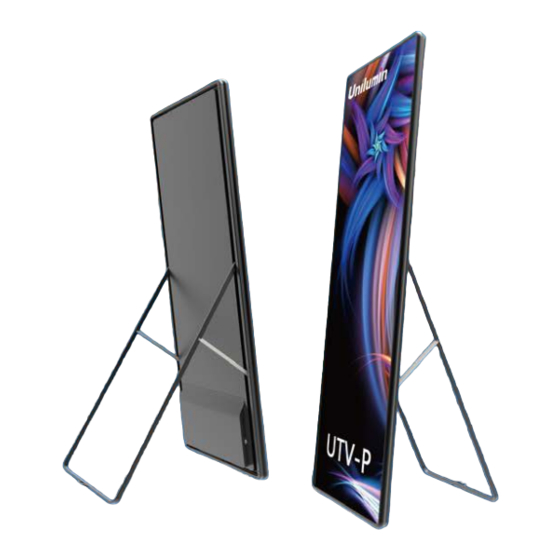
Chapter 1 Product Introduction Chapter 1 Product Introduction The UTV-P series is a new generation of commercial poster LED display product launched by Unilumin. Designed for super light, ultra-thin, high quality and intelligent management. It shows excellent results and supports multiple interface connections. -
Page 14: Specification
Chapter 1 Product Introduction 1.3 Specification Parameter UTV-P 1.8 UTV-P 2.5 Physical Pixel composition 1R1G1B Parameter LED type 3-in-1 Black SMD Pixel Pitch 2.57 Pixels per Cabinet(dots) 320*1080 224*756 Display area(mm) 576(W)*1944(H)*35(D) Cabinet size (Wx Hx D)(mm) 618(W)*1986(H)*35(D) Material Aluminum... -
Page 15: Scope Of Application
Chapter 1 Product Introduction 1.4 Scope of Application The UTV-P series products are extensively used for advertisements in public places such as retail brand stores, shopping malls, hotels, churches, airports, theatres, cinemas, company lobbies, high-end clubs, museums, and large conference rooms. -
Page 16: Chapter 2 Installation Guide
Chapter 2 Installation Guide Chapter 2 Installation Guide 2.1 Out-of-Box Inspection Check whether the packages are damaged. If the packages are intact, check the main components against the shipping list. If any inconsistency is found, contact us in time. The main components include cabinets, signal cable, power cable, USB cable, HDMI cable, maintenance tools and Parts box. - Page 17 Chapter 2 Installation Guide...
-
Page 18: Installation Of Base Support
Chapter 2 Installation Guide 2.2.2 Installation of Base Support Base Limit module Support module Bolt Gasket Fixed module Figure 2-3 Parts Install the limit module. - Page 19 Chapter 2 Installation Guide M5 Bolt Install the support module M8 Bolt Install the fixed module...
- Page 20 Chapter 2 Installation Guide...
- Page 21 Chapter 2 Installation Guide Install the cabinet M5 Bolt...
-
Page 22: Vertical Wall Mounted
Chapter 2 Installation Guide 2.2.3 Vertical Wall Mounted Note: Please install on the wall that can withstand 38KG weight. M8*80mm Impact Drill Wrench Hammer Explosive bolts... - Page 23 Chapter 2 Installation Guide Drill the holes Put the mounting frame close to the wall and adjust the level, make the mark in the hole, take off the mounting frame and drill the hole. Hole Hole Use explosive bolts to fasten the mounting frame to the wall. Hang the top of the cabinet on the mounting bracket...
-
Page 24: Horizontal Wall Mount
Chapter 2 Installation Guide 2.2.4 Horizontal Wall Mount Rotate the cabinet counterclockwise to 90° Installing the retention module at the distance from the edge 500mm, then fasten the cabinet. -
Page 25: Chapter 3 Function Introduction
Chapter 3 Function Introduction Chapter 3 Function Introduction Button Function Before performing control setting on the LED display, confirm that each device is connected correctly. 1. HDMI IN 2. Audio 3. LAN 4. USB 5.USB 6. Config 7. Liquid crystal display board 8. -
Page 26: Display Mode Introduction
Chapter 3 Function Introduction 3.2 Display Mode Introduction 3.2.1 Standalone Mode When the poster is used routinely, each poster can operate independently and display different pictures. The poster screen can be segmented into multiple windows by the software editing of the system. -
Page 27: Replication Mode
Chapter 3 Function Introduction 3.2.2 Replication Mode When multiple posters are routinely connected through HDMI, from left to right the first poster is the controller. In the replication mode, the other entire posters will read the main poster’s information and play the same picture. -
Page 28: Extended Mode
Chapter 3 Function Introduction 3.2.3 Extended Mode When multiple posters are routinely connected through HDMI, from left to right the first poster is the controller. Set all posters to extend mode, the posters’ screens will be connected to a large display screen. -
Page 29: Chapter 4 Basic Setting
Schedule: Conduct timing settings on command contents like play program, sleep, wakeup, reboot, brightness adjustment, etc. 1) After connecting UTV-P to the computer, a player will show up in Direct USB, you can check the specific information and some basic settings about it through selecting... - Page 30 Chapter 4 Basic setting 2) In Program Management, you can conduct a comprehensive management on programs included in UTV-P, and all programs can be deleted in Program Management regardless of the type and source. 3) Schedule Settings: In Schedule Settings, click [ Add ] to add schedule command,...
- Page 31 Chapter 4 Basic setting 4) Commands can be edited and deleted after completing adding schedule commands.
-
Page 32: Advanced Settings
Chapter 4 Basic setting 4.2 Advanced Settings 4.2.1 Playing Parameters ①LED Resolution The [ Width ] / [ Height ] you input must be equal to or slightly larger than the actual screen resolution. ②Input Type: HDMI or Internal Media ③Output [ Every Frame ] (Default) [ Every Other Frame ] (Choose [ Every Other Frame ] can help avoid lag when... -
Page 33: Network Setting
Chapter 4 Basic setting 4.2.2 Network Setting ①WIFI Check [ WIFI ] in network tab, and input your WIFI login information for [ SSID ] and [ Password ], then click [ Apply ] and [ Refresh ] to complete setting, click [ Details ] to check connection status. - Page 34 Chapter 4 Basic setting ②WIFI Hotspot Input your [ SSID ] and [ Password ] to use a WIFI Hotspot; [ Band ]: 2.4G or 5G (5G mode will be faster and more reliable if both smart phone and computer support 5G WIFI) [ Channel ]: 14 or 24 choices, to avoid network overload.
- Page 35 UTV-P will automatically obtain an IP address. 2. [ Use Following IP Address ] To use a specific IP address, enter information for [ IP ], [ Subnet Mask ], [ Gateway ], then connect UTV-P LAN port to the router. 3. [ Details ]...
- Page 36 Chapter 4 Basic setting ④4G Check [ 4G ] in network tab, click [ Apply ] and [ Refresh ] to access 4G network, click [ Test Network State ] to check connection status.
-
Page 37: Chapter 5 Instructions For Operation Under Windows System
Chapter 5 Instructions for operation under Windows System Chapter 5 Instructions for operation under Windows System 5.1 Program Editing Turn on the software, you will see [ LED1 ] in program editing area. Right-click [ LED1 ] to add [ Normal Page ], you can add [ File Window ] in [ Normal Page ], then add [ Image ] and [ Video ] under the [ File Window ] to add media for asynchronous play. -
Page 38: Program Publishing
①In [ Program Editing Area ], after finishing program editing, select the [ Program Page ] that you are going to publish. ②Click [ UTV-P ] and then right-click to choose [ Publish current program to the selected player ], you must rename the program and allow it to finish uploading to... -
Page 39: Publish Program Through Ethernet Port
①In [ Program Editing Area ], after finishing program editing, select the [ Program Page ] that you are going to publish; ②Click [UTV-P ] and then right-click to choose [ Publish current program to the selected player ], you must rename the program and allow it to finish uploading to... - Page 40 Chapter 5 Instructions for operation under Windows System...
-
Page 41: Publish Program Through Usb Disk
Chapter 5 Instructions for operation under Windows System 5.2.3 Publish Program through USB Disk 1. To begin publishing through USB, first insert your USB disk to the PC USB port; Click [ Publish Program to Playboxes ] to extend program publishing window. Note: USB disk should be empty before publishing for best performance. - Page 42 Chapter 5 Instructions for operation under Windows System ②Choose USB Disk Mode: ●Play program from USB disk (Auto play USB disk content after inserting to UTV-P; and the content won’t be stored in UTV-P) ●Update program from USB disk (Auto play USB disk content after inserting to UTV-P;...
-
Page 43: Use Environment
6.1 Use environment When using mobile device control of Android, you need to connect the control device to the hotspot issued by UTV-P, or the control device and UTV-P to connect to the same local area network. 6.1.1 Control device access to UTV-P hotspots UTV-P emits a hotspot by default, which is enough for the first time with a direct connection. - Page 44 Chapter 6 Instructions for operation under Android System 3) Click on the advanced settings, enter the management password 168, enter the management interface: 4) Select the network, check WIFI, enter the LAN account number and password, click on the OK.
-
Page 45: Introduction To Software Interface Features
Chapter 6 Instructions for operation under Android System 6.2 Introduction to software interface features Open the software, enter the main interface: click to refresh, find the terminal. Click : Access to the quick management interface. - Page 46 Chapter 6 Instructions for operation under Android System Search Terminal: Find Online UTV-P; Editing program: directly into the program editing interface, the follow-up will introduce the specific operation; Fast connection terminal: When multiple devices are connected, you can view all device status and choose management;...
- Page 47 Chapter 6 Instructions for operation under Android System After entering the management interface, there are three main modules: control, program, screenshot: ① Control: basic settings management of equipment;...
- Page 48 Chapter 6 Instructions for operation under Android System...
- Page 49 Chapter 6 Instructions for operation under Android System ② Program: Editing and managing the programs that need to be used; All programs that have been played are saved here and can be called directly, or you can edit the program in advance and call it directly if needed. ③...
- Page 50 Chapter 6 Instructions for operation under Android System 6.3 Program Management and Broadcasting 1) Click on the icon in the upper right corner to select ‘Edit Program’. 2) Enter the program management interface, where all the programs that have been played are recorded and can be called directly.
- Page 51 Chapter 6 Instructions for operation under Android System 3) Set the screen size: size refers to the total resolution of the display, UTV-P1.8 resolution is 320 x 1080, UTV-P2.5 resolution is 224 x 756; 4) enter the window settings interface, if there is no multi-screen playback needs, directly add programs, if you need multi-screen display, click on the window, set the screen resolution (Note: set the screen 1 size, need to click on the blank to cancel the selection, and then add the next screen window)
- Page 52 Chapter 6 Instructions for operation under Android System 5) Set the screen 1 size, click blank to cancel the selection, click on the add window, while adjusting the resolution below; 6) After the screen adjustment, click on the screen to add playback material...
- Page 53 Chapter 6 Instructions for operation under Android System 7) Add footage, click on the icon in the upper right corner to send the show 8) Select the device that needs to change the program, click again, and finish sending the program.
-
Page 54: Chapter 7 Instructions For Operation Under Ios System
7.1.1 Control device access to UTV-P hotspots UTV-P emits a hotspot by default, which is enough for the first time with a direct connection. The hotspot name is C6-XXXX, the initial password is 123456789, and if you need to modify it, refer to the 4.2.2 network settings section. - Page 55 Chapter 7 Instructions for operation under iOS System 3) Click on the advanced settings, enter the management password 168, enter the management interface: 4) Select the network, check WIFI, enter the LAN account number and password, click on the OK.
-
Page 56: Introduction To Software Interface Features
Chapter 7 Instructions for operation under iOS System 7.2 Introduction to software interface features Open the software, click on the icon to switch languages, there are Chinese, English, Japanese three choices. Click the "screen control" at the bottom right for screen management;... -
Page 57: Program Quick Release
1) At the find terminal, select the terminal device that needs to change the program; 2) Click to quickly upload images/videos: select the corresponding material file in the mobile album, click "Complete", the program is sent, complete the UTV-P program changes. - Page 58 Chapter 7 Instructions for operation under iOS System 2) Click on the icon to create a new program, according to the playback content selection type of pictures / videos, picture text, single lines of text, multi-line text, etc. 3) After selecting the type, it will automatically enter the add footage interface, if you do not need multi-screen playback, directly add footage can be published;...
- Page 59 Chapter 7 Instructions for operation under iOS System 4) Multi-screen settings: after clicking back in the previous step, modify the window coordinates and resolution below 5) After the window adjustment, the footage management. Click on the window and select Edit:...
- Page 60 Chapter 7 Instructions for operation under iOS System 6) Go into the add edith interface. Click to add footage, click on the properties to edit the form of footage;...
- Page 61 Chapter 7 Instructions for operation under iOS System 7) After the material is added, click on the upper right corner to send the program;...
-
Page 62: Chapter 8 Daily Maintenance
Chapter 8 Daily Maintenance Chapter 8 Daily Maintenance 8.1 Daily Maintenance The screen surface (including PC glass) is strictly prohibited from being hit and scraped by other sharp objects, do not put product in high temperature, high humidity and strong magnetic environment to avoid direct sunlight. Do not use strong oxidizer or other washing products to wipe PC glass. -
Page 63: Chapter 9 Troubleshooting And Component Replacement
Chapter 9 Troubleshooting and Component Replacement Chapter 9 Troubleshooting and Component Replacement 9.1 Common Faults and Troubleshooting Methods Failure Fault description Troubleshooting method phenomenon 1. confirm whether the power supply is normal 2. the flicker of the signal indicator, such as Open the power Failure in no flicker, confirms whether the screen is... - Page 64 Chapter 9 Troubleshooting and Component Replacement 1. confirm that the U disk is able to read and U disk cannot write normal data and check the format of U disk cannot load the video or the U disk (default FAT32) update content picture 2.
-
Page 65: Replacement Of Main Components
Chapter 9 Troubleshooting and Component Replacement 9.2 Replacement of main Components 9.2.1 Replacement of Module Step Picture Description Remove the frame fix part(each one on the top and bottom) Remove the frame Take out the PC glass Remove the faulty module and replace with a new one... -
Page 66: Replacement Of Power Supply
Chapter 9 Troubleshooting and Component Replacement 9.1.2 Replacement of Power Supply Step Picture Description Remove the rear cover Remove the screws Power supply cover plate Find the faulty power supply and replace with a new one. -
Page 67: Chapter 10 Packaging Transportation And Storage
Chapter 10 Packaging Transportation and Storage Chapter 10 Packaging Transportation and Storage 10.1 Packaging The UTV-P series products would be packaged with flight case. Figure10-1 Package 10.2 Transportation The cabinets must be packaged before transportation. The product shall not be placed upside down or horizontally, and must be protected against the wind, rain, direct sunlight, and corrosive liquid during transportation. -
Page 68: Chapter 11 After-Sales And Warranty
Unilumin provides warranty service to the products meet the requirements of this warranty term. Including quality problem, materials problem and manufacturing problem during normal use. Unilumin has the right to judge whether the product has defects and problems. 11.3.1 Warranty service type 1)Free Online Remote Service:... -
Page 69: Disclaimer
Unilumin to make a preliminary fault judgment. If the on-site analysis by Unilumin engineers determines that the quality problem is not covered by the warranty, the customer shall pay the travel expenses of the engineer and pay the technical service fee according to the after-sales service standard. -
Page 70: Warranty Service Process
16) Unilumin’s product don’t work or damage due to the match with equipment such as broadcasting and control system which are not provided by Unilumin, If the maintenance is required, the charging standard shall be implemented according to the contract. -
Page 71: Warning
In order to avoid damage to the returned items during logistics, please pay attention to the packaging and protection of the products. Unilumin will not be responsible for any damage to the products or parts returned to Unilumin. - Page 72 Chapter 11 After-Sales and Warranty turning the equipment off and on, the user is encouraged to try to correct the interference by one or more of the following measures: -Reorient or relocate the receiving antenna. -Increase the separation between the equipment and receiver. -Connect the equipment into an outlet on a circuit different from that to which the receiver is connected.
- Page 73 (including any agent, distributor or sales representative) is authorized to make any representations or warranties that are different from this warranty. Unless confirmed by Unilumin in the form of the contract, attachments, etc., any warranty and content that conflicts with the terms of this warranty policy will automatically become invalid.
- Page 74 Chapter 11 After-Sales and Warranty 11.8 Product Warranty Card Product Warranty Card Warranty Order No. Shipment Date Period Product Product Model Quantity Customer Contact Name Information Customer Address: Remark(s): Warranty Record Completion Signature of Warranty Date Fault and Troubleshooting Date Customer...
- Page 75 Daya Bay manufacturing center: Longsheng Fifth Road, western Daya Bay, Huiyang District, Huizhou, China. Telephone (switchboard): +86-755-29918999 Fax: +86-755-29912092 Website: www.unilumin.com Service Department Tel: + 86- (0) 755-29592226 (direct line) 24-hour service hotline: 400-677-3888 Display sales department International department (direct line): + 86- (0) 755-29918999...
- Page 76 RUSSIA POST-SALE SERVICE CENTER Address: Russia, 111250, Moscow,Zavoda Serp I Molot Drive,D.10 Tel: +86-755-29918999 SINGAPORE Address: 10 Ubi Crescent #07- 36, Lobby B Ubi Techpark, Singapore 408564 E-mail: sales@unilumin.com UNILUMIN GROUP CO., LTD (JAPAN) Address: 6-chōme-104 Aioichō Naka-ku, Yokohama, Kanagawa, Japan...
- Page 77 UNILUMIN GERMANY GMBH Address: Raiffeisenstr. 30 - 70794 Filderstadt E-mail: info@unilumin.de Tel: +49 711 38967 898 UNILUMIN AUSTRALIA PTY LTD (BUSINESS IN OCEANIA) Address: Level 1, Trak Centre, 443/449 Toorak Road, Toorak, VIC 3142 Tel: +61 3 9006 8960 +86-755-29918999...
Need help?
Do you have a question about the UTV-P and is the answer not in the manual?
Questions and answers