Table of Contents
Advertisement
Advertisement
Table of Contents

Related Manuals for Unilumin SC Series


Summary of Contents for Unilumin SC Series
- Page 1 Unilumin | SC series All-in-one LED Display Product Manual 产品使用手册...
- Page 2 S All-in-one Led Display Revivsion History Brief Introduction of Revise Number Version Revision Date Contents First Version Initial issue 2024-03-14 The contents of this manual are subject to modification without prior notice. 1 / 43...
- Page 3 (including but not limited to color, size, screen display, etc.) please refer to the actual product. Copyright The copyright of this manual belongs to Shenzhen Unilumin Technology Co., Ltd., UniluminLED operational software is developed based on Windows and Android systems. Without written permission, no other individual or organization may extract, reprint, copy, translate, edit, publish or store this software in the retrieval system for other occasions.
- Page 4 10) It is strictly prohibited for users to personally install APK application software that has not been tested by Unilumin; If the system is stuck or crashed due to this reason, please contact the professional personnel; 11) In the living environment, the product may cause radio interference, and practical measures shall be taken to deal with the interference;...
- Page 5 S All-in-one Led Display There is a great possibility that the best display effect cannot be obtained due to ignoring the contents of attention. When installing and repairing products, antistatic gloves and antistatic wrist strap must be worn; The storage environment of the display screens shall be ventilated and dry, and the humidity shall not exceed 85%;...
-
Page 6: Table Of Contents
S All-in-one Led Display Contents ............7 CHAPTER 1 PRODUCT INTRODUCTION CHAPTER 1 PRODUCT INTRODUCTION ............7 1.1 P ................7 RODUCT NTRODUCTION 1.2 P ................... 7 RODUCT EATURES 1.3 P ................8 RODUCT APPEARANCE 1.4 S ............... 9 PECIFICATION ARAMETERS 1.5 S ................ - Page 7 S All-in-one Led Display 3.5 S ............... 28 YSTEM ESCRIPTION 3.6 I ..............29 NTRODUCTION OF OFTWARE 3.6.1 Signal source ..................29 3.6.2 Wireless Projection ................30 3.6.3 File Browser ..................32 3.6.4 Welcome Wall ................... 33 3.6.5 Browser ..................34 3.6.6 Other Applications ................
-
Page 8: Chapter 1 Product Introduction
Chapter 1 Product Introduction 1.1 Product Introduction SC series all-in-one LED Display is the third generation of commercial LED TV products of our company.SC is a new generation of intelligent display screen based on the concept of hard and soft combination and integrated design, which will perfectly replace the traditional display equipment in large and medium-sized conference rooms. -
Page 9: Product Appearance
Chapter 1 Product Introduction 1.3 Product appearance 8 / 43... -
Page 10: Specification Parameters
Chapter 1 Product Introduction 1.4 Specification Parameters UTV SC108 UTV SC135 UTV SC162U Specifications and Models Display Size (inch) 1.25 1.5625 0.9375 Dot Spacing (mm) Overall Dimensions (W/H) 2411x1476x30.4 3011x1813.5x30.4 3611x2151x30.4 (mm) 1920X1080 1920X1080 3840X2160 Screen Resolution (W× H) Full front Full front Full front Maintenance Method... - Page 11 Chapter 1 Product Introduction Standard Android 11.0 Operating System Cotex A73*4+A53*4 Mali-G52 MP8 DDR4 8G/64G Memory/Storage SPDIF*1/USB2.0*1/HDMI in*2/USB3.0*3/Audio Out*1/RJ45*2 External Interface Support Wireless Projection Support Remote Control Operation Wanlibo Sound Brand 12W/8Ω*2 Rated Power (W) Built-in(Support customer outsourcing) Fixed mode 90~20KHz Frequency Response 79±3dB...
-
Page 12: Scope Of Application
Chapter 1 Product Introduction 1.5 Scope of Application SC is widely used in indoor spaces such as conference rooms and multi-function halls of schools. At the same time, it can also be used in public places such as studios, airports, stations, urban subways, as well as exhibition halls, shopping malls, brand stores, promotion sites, home theaters and other fields. -
Page 13: Chapter 2 Equipment Installation
Chapter 2 Equipment Installation Chapter 2 Equipment Installation 2.1 Installation Method Wall-mounted Mobile Bracket To install the equipment, it requires to drill It provides standard mobile bracket, which mounting holes in the wall, so the wall must can be installed on the flat level floor without be solid. -
Page 14: Preparation Before Installation
Chapter 2 Equipment Installation 2.3 Preparation Before Installation 2.3.1 Installation Precautions This equipment must be installed by at least 2 professional technicians. If the network cable or power socket (such as through-wall wiring) needs to be re-laid before installation, the customer needs another professional to complete it in advance, and the specifications must meet the requirements of the equipment. -
Page 15: Preparation Tools
Chapter 2 Equipment Installation Please confirm the installation size, and check the corresponding dimension figure and wiring diagram in the attachment. 2.3.2 Preparation Tools Tool Name Explanation Illustration Used to drill in Chopping bit φ10 wall and install (wall-mounted expansion need) screws... - Page 16 Chapter 2 Equipment Installation Used for Paper cutter equipment and module unpacking Used to Tape measure dimensions Hexwrench Used to lock the (included with Cabinet goods) Used for Phillips screwdriver Phillips head (included with screws and goods) install Sound Used to drive Open End expansion Wrencehers...
-
Page 17: Equipment Unpacking
Chapter 2 Equipment Installation Used to install Slotted screwdriver or remove the cabinet (included with positioning goods) column 2.4 Equipment Unpacking Firstly, please carefully check whether the packaging is damaged. If the packaging is normal, continue to examine the shipping list to check the main components. If there is any discrepancy, please contact us in time. - Page 18 Chapter 2 Equipment Installation Step 2: Beam fixing. The height of the beam from the ground can be determined according to the height of the conference table and the wall surface. Attach the beam to the determined position, keep beam level with a gradienter, and mark the hole position with a marker. Then punch the marked holes with percussion drill, and finally fix the beam with expansion screws.
- Page 19 Chapter 2 Equipment Installation Step 3: Cabinet installation. Take out the Cabinets, hang the cabinet to the beam according to the coding sequence. Lock the box to the hanging bracket connection screws with an allen wrench. Finally, lock the lateral box to the box with an allen wrench to connect and organize the power and network cables in the bottom bezel.
- Page 20 Chapter 2 Equipment Installation Step 4: Bottom Border Installation. Splicing the left and right control boxes through the control box connection board, and fixing the control box on the screen body, connecting the power cable and network cable. 19 / 43...
- Page 21 Chapter 2 Equipment Installation 20 / 43...
- Page 22 Chapter 2 Equipment Installation Step5: Module installation. Take out the modules and install them to the cabinets according to the coding sequence. The module will be adsorbed on the surface of the Cabinet by magnets. Please read the following Attention during installation: 21 / 43...
- Page 23 Chapter 2 Equipment Installation Step6: After the installation, plug in and light it up. We have already done luma corrector and LED parameter configuration before leaving the factory, so this product does not need software debugging on site. If you want to know the specific parameters and debugging methods, please contact us for technical support.
-
Page 24: Installation Of Mobile Bracket
Chapter 2 Equipment Installation Attention When installing the module, you must be careful and pay attention to the following matters: 1. Antistatic gloves must be worn on both hands. In addition to antistatic effect, gloves can also keep the surface of the module clean. -
Page 25: Inspection After Installation
Chapter 2 Equipment Installation 2.6 Inspection after Installation Number Check Items Check Mode Whether the overall installation of the equipment is horizontal, whether the height is appropriate, whether the full screen can be seen when sitting at the last position of the View conference table, and the overall viewing angle is good. -
Page 26: Chapter 3 Equipment Use
Chapter 3 Equipment Use 3.1 Instructions of Remote Control 3.2 Description of External Interface... -
Page 27: Power On And Power Off
3.3 Power on and Power off 1)Plug in and turn on the power switch to start the equipment. 2)When the indicator light is red, the equipment is in standby state. At this time, press the on/off button of the remote control. 3)Power off:Press the on/off button of the remote control, equipment standby, indicator light is red. -
Page 28: Networks And Hotspots
3.4 Networks and Hotspots You can connect the device to the network and turn on the hotspot according to the following operations. 1)Wired access network 2)Wireless access network 3)Turn on hotspot... -
Page 29: System
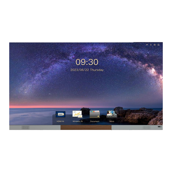
3.5 System Page Description SC uses its own business UI system. The home page displays the network status, clock, common software bar, Hiboard, etc. It is convenient for you to give priority to the operation in the meeting. At the same time, you can customize the layout through Themes according to your personal preferences. -
Page 30: Introduction Of Software
3.6 Introduction of Software 3.6.1 Signal source 1)Select signal source... -
Page 31: Wireless Projection
2) Exit signal source When you need to exit the HDMI signal source,please press the Back button on the remote control and select Yes to exit.Or press the HOME key to directly return to the system main page. 3.6.2 Wireless Projection You can project your mobile phone, tablet or computer onto the screen by wireless projection without any cable connection. - Page 32 2) Software Projection: Enter https://transcreen.app/ or scan QR code through mobile phone to download Transcreen client, achieve projection by Transcreen. Applicable equipment: Android phones, Android tablets, Windows computers. 1.The mobile device is connected to the screen hotspot or connected to the same network segment as the screen. 2.Open the installed Transcreen client for projection.
-
Page 33: File Browser
3)Airplay Projection: Applicable equipment: Iphone, Apple computer, iPad. No need to install software 1.The apple device is connected to the screen hotspot or connected to the same network segment as the screen 2.Turn on the Airplay function of the Iphone for projection 1,... -
Page 34: Welcome Wall
3.6.4 Welcome Wall Through the welcome wall, you can display your meeting or event theme on the home page more quickly. Entering the interface of “welcome wall”, click “More” to edit various style of welcome wall interface. You can use flying mouse mode and virtual keyboard of the remote control to edit, and also can access the mouse and keyboard through the USB port for operation. -
Page 35: Browser
3.6.5 Browser We have built-in UBrowsers specially designed for large screens. Users can quickly enter search content through the search box on the home page, and enjoy the browsing experience of large screen pages. 3.6.6 Other Applications We support you to install other apps, but there is no guarantee that the device is compatible with applications other than those we develop or test. -
Page 36: Settings
3.6.7 Settings In the setting interface, you can set up related systems such as network connection, timing on/off, time and date, etc. -
Page 37: Chapter 4 Common Troubleshooting And Component
Chapter 4 Common Troubleshooting and Component Replacement 4.1 Common Troubleshooting 4.1.1 Blank Screen Reason analysis: 1) The power supply of the equipment is not turned on or the equipment is in standby state 2) The hardware of the system is abnormal Elimination methods: 1) Check the power input and equipment operation indication status 2) Check the system card inside the power box. -
Page 38: Chromatic Aberration Exists In A Module In The Display Screen
2) The connection of the pinboard data interface is poor Elimination methods: 1) Replace the module and check whether the module is abnormal 2) Replace the pinboard or the data interface of the pinboard 4.1.4 Chromatic aberration exists in a module in the display screen Reason analysis: 1) The calibration data of the module has not been uploaded Elimination methods:... -
Page 39: Chapter 5 Drawings
Chapter 5 Drawings Note: We are sorry that our products may be updated without any notice, so the following drawings may not be the latest and only for reference , if you have any doubts, please do not hesitate to contact us. 5.1 UTV SC108 Drawings (1-1)... -
Page 40: Utv Sc135 Drawings
5.2 UTV SC135 Drawings (2-1) UTV SC135 Mobile bracket installation (2-2) UTV SC135 Wall mounted installation... -
Page 41: Utv Sc162U Drawings
5.3 UTV SC162U Drawings (3-1) UTV SC162U Mobile bracket installation (3-2) UTV SC162U Wall mounted installation... -
Page 42: Contact Information
Pingshan manufacturing center: No. 6 North Lanjing Road, Pingshan New District, Shenzhen Daya Bay manufacturing center: Longsheng Fifth Road, western Daya Bay, Huiyang District, Huizhou. Telephone (switchboard): + 86- (0) 755-29918999 Fax: + 86- (0) 755-29912092 Website: www.unilumin.com Service Department Tel: + 86- (0) 755-29592226 (direct line-24-hour service hotline: 400-677-3888...
Need help?
Do you have a question about the SC Series and is the answer not in the manual?
Questions and answers