Table of Contents
Advertisement
Advertisement
Table of Contents

Subscribe to Our Youtube Channel
Related Manuals for Unilumin Upanel 0.9S


Summary of Contents for Unilumin Upanel 0.9S
- Page 3 Upanels Product Manual Revision Records Version Revised Content Date Initial release Jun. 13, 2016 Optimized playback setting Oct. 17,2016 Modify the cable connection Jan.16,2018 diagram Optimized internal configuration and Jan.25,2019 functionality The manual may be modified without any prior notice.
- Page 4 Copyright The manual is the property of Unilumin Group Co., Ltd. The Unilumin LED’s operating software is developed based on the Windows operating system. No part of the manual can be transcripted, transmitted, reproduced, translated, edited, published, stored to a retrieval system, or used in any form by any individual or organization without a prior written permission of Unilumin.
- Page 5 Upanels Product Manual Read the following content carefully to ensure correct use of the LED display products: WARNING! The LED display may be damaged and become irreparable if you ignore the following warnings. Do not place the LED display upside down or throw it during transport and storage. Do not incline, scratch, or crash the LED display during installation.
- Page 6 Upanels Product Manual CAUTION! The optimum displaying effect may fail to be achieved if you ignore the following cautions. Wear antistatic gloves when installing or repairing the product. Ensure good ventilation for the LED display when designing the heat dissipation solution.
-
Page 7: Table Of Contents
Upanels Product Manual Contents Chapter 1 Product Introduction ................. 1 1.1 Features ....................1 1.2 Cabinet Appearance ................. 2 1.3 Specification ....................3 1.4 System Solution ..................4 1.5 Scope of Application ................. 5 Chapter 2 Installation and Wiring ..............6 2.1 Out-of-Box Inspection ................ - Page 8 Upanels Product Manual 4.3 Editing Professional Playing Solution ............. 41 4.3.1 Editing the Time Segment ..............41 4.3.2 Editing the Program Page ..............43 4.3.3 Editing the Display Window ............... 46 4.3.4 Editing the Media ................49 4.3.5 Playing the Media ................53 4.4 Saving and Opening a Playing Solution ..........
- Page 9 Upanels Product Manual Attachment 1 - Product Warranty Card ............69 Attachment 2 - Path of Signal Cable inside the Cabinet ......... 70 Contact Information ..................71...
-
Page 11: Chapter 1 Product Introduction
Chapter 1 Product Introduction Chapter 1 Product Introduction The Upanels series is a pioneering product in the industry in that it is a small pitch LED display product that supports contactless smart maintenance. The Upanels series is installed on the wall and the modules, control cards, power supply, and cables can be installed and removed from the front side of the LED display. -
Page 12: Cabinet Appearance
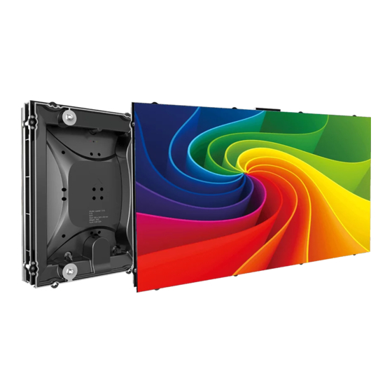
Chapter 1 Product Introduction 1.2 Cabinet Appearance 1. Signal/power port 2. Cabinet mounting hole 3. Module safety rope 4. Power supply box 5. Positioning slot (with screw hole) 6. Operating status indicator light 7. Module bracket 8. Module ejection sensor 9. -
Page 13: Specification
Chapter 1 Product Introduction 1.3 Specification Parameter Upanel0.9S Upanel1.2S Upanel1.5S Upanel1.9S Pixel composition 1R1G1B LED type 3-in-1 Black SMD Pixels per panel(dots) 640x360 480x270 384x216 320x180 Cabinet size Physical 609.92x343.08x71 (WxHxD) (mm) Parameter Size ratio 16:9 Die-casting aluminum(cabinet)/ Material Die-casting magnesium(module) Weight(kg) Grey scale(bits) Refresh rate(Hz) -
Page 14: System Solution
Chapter 1 Product Introduction 1.4 System Solution The display system consists of the LED display, sending box, control PC, matrix, splicing controller and power distribution box (refer to the shipping list for details). The following shows a topology of the system for reference: Figure 1-2 System Topology... -
Page 15: Scope Of Application
Chapter 1 Product Introduction 1.5 Scope of Application The Upanels series products can be assembled seamlessly into a screen of any size, and are extensively used as fixed LED displays for advertisements in public places such as retail brand stores, shopping malls, hotels, banks, churches, airports, bus stations, theatres, cinemas, company lobbies, high-end clubs, museums, and large conference rooms. -
Page 16: Chapter 2 Installation And Wiring
Chapter 2 Installation and Wiring Chapter 2 Installation and Wiring 2.1 Out-of-Box Inspection Check whether the packages are damaged. If the packages are intact, check the main components against the shipping list. If any inconsistency is found, contact us in time. The main components include cabinets, signal cable, power cable, USB cable, DVI cable, and sending box. - Page 17 Chapter 2 Installation and Wiring Insert the nut piece into the aluminium profile. Fig 2-2 Installation Diagram 1 Mark and drill holes on the wall based on the installation drawing. Fasten the embedded plate onto the wall and install the aluminium profile onto the plate. Check the installed aluminium profile to ensure that its levelness is within ±1 mm.
- Page 18 Chapter 2 Installation and Wiring Install part of the vertical back frames without tightening the screws. Install 2*2 cabinets from the bottom and adjust the vertical back frames. Then tighten the screws on the vertical back frames. Install other vertical back frames in a similar way.
- Page 19 Chapter 2 Installation and Wiring Fig 2-9 Installation Diagram 4 Connect the power cables and signal cables based on the wiring diagram for the delivered product. Turn on the power and check the power supply for each cabinet. Place the modules sequentially into the empty cabinets from right to left and from bottom to top based on the serial number indicated on each module (place Module A-1 to the bottom right corner viewed from the front side of the LED display).
- Page 20 Chapter 2 Installation and Wiring Wrap the edge cover of the LED display after the LED display operates normally. Fig 2-11 Installation Diagram 6 Fig 2-12 Installation Diagram 7...
-
Page 21: Wiring For Led Display
Chapter 2 Installation and Wiring 2.3 Wiring for LED Display 2.3.1 Common Cables Incoming Power Cables DVI Cable USB Cable Power/Signal Incoming Incoming Signal Cable Cable Switching Board... -
Page 22: Signal Cable Connection
Chapter 2 Installation and Wiring 2.3.2 Signal Cable Connection Figure 2-13 ~ Figure 2-16 shows the signal cable connection for display with a resolution of 1920 x 1090. Signal cables shall be connected based on the wiring diagram of the delivered products for the project. Figure 2-13 Signal Cable Connection Diagram of Upanels 0.9 Figure 2-14 Signal Cable Connection Diagram of Upanels 1.2... - Page 23 Chapter 2 Installation and Wiring Figure 2-15 Signal Cable Connection Diagram of Upanels 1.5 Figure 2-16 Signal Cable Connection Diagram of Upanels 1.9...
-
Page 24: Power Cable Connection
Chapter 2 Installation and Wiring 2.3.3 Power Cable Connection Figure 2-17 ~ Figure 2-20 shows the power cable connection for display with a resolution of 1920 x 1090.Power cables shall be connected based on the wiring diagram of the delivered products for the project. AC Power Cable Figure 2-17 Power Cable Connection Diagram of Upanels 0.9 AC Power Cable... - Page 25 Chapter 2 Installation and Wiring AC Power Cable Figure 2-19 Power Cable Connection Diagram of Upanels 1.5 AC Power Cable Figure 2-20 Power Cable Connection Diagram of Upanels 1.9...
-
Page 26: Smart Control Distribution Box
Chapter 2 Installation and Wiring 2.3.4 Smart Control Distribution Box The Smart Control Distribution Box can be used for distributing electric power to the LED display, and has the function for real-time monitoring of the temperature, humidity, smoke, and mains voltage of the external environment. The control software has the scheduled start/stop function, allowing you to set any time for the LED display to be remotely started or stopped. - Page 27 Chapter 2 Installation and Wiring PLC connection of the smart control distribution box: The PLC communication system is RS485, It uses converter from control computer RS232 to RS485. For more detail information, please refer to our Intelligent Power Distribution Management System Manual. Figure 2-22 Distribution Box PLC Connection Diagram...
-
Page 28: Chapter 3 Led Display Control Setting
Chapter 3 LED Display Control Setting Chapter 3 LED Display Control Setting 3.1 Power-on Testing Before performing control setting on the LED display, confirm that each device is connected correctly. Before turning on the power of the LED display, you must use a multimeter to test the live wire, neutral wire, and ground wire of the AC power supply, in order to ensure they are not conductive with each other. -
Page 29: Preparation
Chapter 3 LED Display Control Setting 3.2 Preparation 3.2.1 Starting the Hardware Start the control PC Windows system. After the graphics card driver is activated, set graphics card of the control PC to replication mode and confirm that the green indicator of the sending box is blinking normally (blinking once per second). -
Page 30: Display Configuration
Chapter 3 LED Display Control Setting 3.3 Display Configuration Run UniLCT-Mars. Make sure that Control System on the main window is 1. Click the User option and select Advanced Login, as shown in Figure 3-3. Figure 3-3 Main Window of UniLCT-Mars Enter the initial password “admin”, as shown in Figure 3-4, to go to the advanced user window. - Page 31 Chapter 3 LED Display Control Setting Click Next, as shown in Figure 3-6: Figure 3-6 Screen Config The following window is displayed. Set Sending Board Resolution (1920×1080 recommended). Set Graphics Output Resolution to the same value as Sending Board Resolution. Then click Save to save the settings. Figure 3-7 Sending Board Configuration...
- Page 32 Chapter 3 LED Display Control Setting After configuring the parameters on the Sending Board page, click Scan Board to display the following window: Figure 3-8 Scan Board Configuration Click Load File to load the file xxxx.rcfg stored in the optical disk. Click Send to HW.
- Page 33 Chapter 3 LED Display Control Setting After configuring the parameters on the Scan Board page, click Screen Connection to display the following window: Click Read File to load the file xxxx.scr stored in the optical disk, as shown in Figure 3-9. Figure 3-9 Screen Connection 1...
-
Page 34: Brightness Adjustment
Chapter 3 LED Display Control Setting Click Send to HW. After sending, confirm that the screen is complete. Then click Save. Figure 3-10 Screen Connection with Loaded File 3.4 Brightness Adjustment On the main window, click Brightness, as shown in Figure 3-11, to display the brightness adjustment interface: Figure 3-11 Main Window for Advanced User... - Page 35 Chapter 3 LED Display Control Setting There are four brightness adjustment modes, namely Manual, Schedule, Auto, and Auto Adjustment by Hardware. After adjustment is finished, click Save to HW to save the adjustment results to the hardware. Manual Adjustment Select Manual and adjust the brightness by dragging the scroll bar below Brightness Adjustment or directly modifying the brightness value (the maximum value is 255) next to the scroll bar.
-
Page 36: Correction Coefficient Management
Chapter 3 LED Display Control Setting Automatic Adjustment Schedule, Auto, and Auto Adjustment by Hardware are automatic adjustment modes. Automatic adjustment function is not recommended for indoor LED display products because the indoor environment has stable ambient light and is rarely affected by the ambient brightness. - Page 37 Chapter 3 LED Display Control Setting Configure Enable/Disable Calibration to Brightness, click Save, and then click Manage Coefficients to display the following window: Figure 3-14 Manage Coefficients Upload coefficients: Upload the correction coefficient database generated by the software or read back by the display screen to the screen. Save coefficients to database: Read back and save the coefficients from the screen to the coefficient database.
-
Page 38: Setting Coefficients For A New Receiving Card
Chapter 3 LED Display Control Setting 3.5.1 Setting Coefficients for a New Receiving Card 1) As shown in Figure 3-15, select Topology or List. Select the position of the replaced receiving card. Click Next: Figure 3-15 Selecting Area for New Receiving Card 2)... - Page 39 Chapter 3 LED Display Control Setting Select the corresponding correction coefficients: Figure 3-17 Selecting Correction Coefficients for Receiving Card Select Stable Upload and click Next: Figure 3-18 Uploading Correction Coefficients...
- Page 40 Chapter 3 LED Display Control Setting Adjust Coefficient: Perform a simple adjustment if the displaying effect is not good enough after you upload the coefficient. Then click Next. Figure 3-19 Simple Adjustment Red:Adjust the red brightness value of calibration coefficients. Green:Adjust the green brightness value of calibration coefficients.
-
Page 41: Setting Coefficients For A New Module
Chapter 3 LED Display Control Setting 3.5.2 Setting Coefficients for a New Module Select Position of the New Module: Select Topology or List. Then select the position of the receiving card where the new module is located. Double click the selected position: Figure 3-21 Selecting Cabinet for the New Module... - Page 42 Chapter 3 LED Display Control Setting Choose Display Mode to Modules. Select the position of the new module and click Next. Figure 3-22 Selecting Position of New Module Module Size:Set the size of the module in a cabinet. The software determines each module arrangement based on module size and cabinet size.
- Page 43 Chapter 3 LED Display Control Setting Save the correction coefficients to the hardware (Use similar steps in setting coefficients for a new receiving card. For details, refer to Step 4, Step 5, and Step 6 in Section 3.5.1) so that they are retentive after a power failure. Figure 3-23 Obtaining Correction Coefficients for a New Module...
-
Page 44: Pre-Storing Picture
Chapter 3 LED Display Control Setting 3.6 Pre-storing Picture On the Prestore Picture interface, you can save a picture as the prestored picture for the screen. This prestored picture can be set as a screen displayed upon booting, signal cable disconnection, or DVI signal absence. On the main window, click Tool and select Prestore Picture, as shown in Figure 3-24. - Page 45 Chapter 3 LED Display Control Setting 1) Prestore Picture Settings Select Picture: Click Browse to select the directory of the picture. Screen Effect: Set the selected picture to be displayed on the whole screen by means of stretching, tiling, or centering. Cabinet Effect: Set the selected picture to be displayed on each cabinet of the screen by means of stretching, tiling, or centering (the number of pictures displayed by each cabinet shall be equal to the number of receiving cards in the cabinet).
- Page 46 Chapter 3 LED Display Control Setting .3.7 Dehumidification Mode In the main window, click "Tools" - "SD600E Dehumidification" to enter the dehumidification interface. Figure 3-25 Dehumidification Setting Select the corresponding dehumidification module and click “Settings” to enter the corresponding dehumidification mode. Figure 3-26 Dehumidification Interface...
- Page 47 Chapter 3 LED Display Control Setting There are three dehumidification mode levels, and the dehumidification time corresponding to different dehumidification levels is different. Exit the dehumidification mode and select the normal mode. The default brightness value is 60% after exiting the dehumidification mode.
-
Page 48: Chapter 4 Led Display Playing Setting
Chapter 4 LED Display Playing Setting Chapter 4 LED Display Playing Setting 4.1 Selecting a Playing Solution The playing software UniStudio has three playing modes, namely Simple playing program, Professional playing program, and Priority programs of the page. Professional playing program is used most commonly. This Section introduces the Professional playing program only. -
Page 49: Playing Setting
Chapter 4 LED Display Playing Setting 4.2 Playing Setting 4.2.1 Display Window Setting Run the UniStudio, click Settings and select Display Setting, as in following fig: Figure 4-3 Display Window Setting Number of Display Windows: Indicates the number of display windows. To increase or decrease the number of display windows, re-enter the number of display windows in the box next to Number of Display Windows and then click Update. -
Page 50: Startup Setting
Chapter 4 LED Display Playing Setting 4.2.2 Startup Setting On the main window of the software, click Setting > Start Setting to enable the software to run automatically upon startup of the PC and to automatically activate a playing solution. See Figure 4-4: Figure 4-4 Startup Setting Auto Run after Power-on: If you enable this function, UniStudio will run automatically the next time when the PC is started. -
Page 51: Editing Professional Playing Solution
Chapter 4 LED Display Playing Setting Enable Auto Play: If you enable this function and specify a playing solution for the screen, the software will automatically activate the specified playing solution once the software is started. Instant plug and play of USB disk: If you enable this function, the PC will automatically read and activate the playing solution once the USB flash drive is inserted to the PC. - Page 52 Chapter 4 LED Display Playing Setting Editing the properties of the playing solution After adding a general time segment or interstitial segment, click General Segment 1 to edit the properties displayed in the segment editing area on the right side, as shown in Figure 4-6: Figure 4-6 Properties of General Time Segment...
-
Page 53: Editing The Program Page
Chapter 4 LED Display Playing Setting 4.3.2 Editing the Program Page Creating a program page As shown in Figure 4-7, right click General Segment or click the Add Program Page button in the toolbar to create a program page: Figure 4-7 Creating a Program Page... - Page 54 Chapter 4 LED Display Playing Setting Setting the properties After creating the program page, click Program 1 and set the background, displaying mode, and other properties displayed on the property page on the right side. See Figure 4-8: Figure 4-8 Properties of Program Page If you select Specify Number of Times, the next general program page is played after the preset Times to Play for the display window with the longest playing time on the current program page has been reached.
- Page 55 Chapter 4 LED Display Playing Setting When the current program page is played, the background picture or colour of the program page is displayed in the area not covered by the display window, as shown in Figure 4-9: Figure 4-9 Background of Program Page After adding the program page, you can move, copy, paste, or delete the program page by using the toolbar in the program page editing area, or by using the short-cut menu, as shown in Figure 4-10.
-
Page 56: Editing The Display Window
Chapter 4 LED Display Playing Setting 4.3.3 Editing the Display Window Adding a display window After adding a program page, you need to add a display window to this program page. Click Add Window on the toolbar of the program page to add a window to the current program page. - Page 57 Chapter 4 LED Display Playing Setting Setting the location and size of the display window The location and size of the new window is generated randomly and can be adjusted based on actual conditions by using either of the following two methods: Directly specify the new location and size in the setting pane, as shown in Figure 4-13: Figure 4-13 Setting the Window Size...
- Page 58 Chapter 4 LED Display Playing Setting Deleting a display window Select the window to be deleted. Click the delete key to delete the window, as shown in Figure 4-15: Figure 4-15 Deleting the Display Window Moving a display window Select the program or window. Click the direction key to adjust the playing sequence, as shown in Figure 4-16: Figure 4-16 Moving a Display Window...
-
Page 59: Editing The Media
Chapter 4 LED Display Playing Setting 4.3.4 Editing the Media Adding the media The type of window for adding the media is Common Window. Click the Add Media button of a common window to select media of different types to be added into the media list. - Page 60 Chapter 4 LED Display Playing Setting After adding the media, you can set the media texts and properties, as shown in Figure 4-18. Figure 4-18 Media Setting Window Setting the media properties Different media have different properties. After a medium in the media list is selected, the property page of this medium is displayed below the selected medium.
- Page 61 Chapter 4 LED Display Playing Setting Editing the media in the common window In an actual application, if different playing times are required for different media, you can select the media in the media list and then double click Times to Play to modify the playing times by either entering a new value or selecting a value from the drop-down list.
- Page 62 Chapter 4 LED Display Playing Setting Right click the media to perform operations on the selected media, as shown in Figure 4-21: Figure 4-21 Media Operation Menu Right click a blank area in the media playlist. A media playing menu is displayed, as shown in Figure 4-22: Figure 4-22 Media Playing Menu...
-
Page 63: Playing The Media
Chapter 4 LED Display Playing Setting 4.3.5 Playing the Media After the playing mode is edited or loaded, click the play key on the main toolbar to start the current playing mode, as shown in Figure 4-23: Figure 4-23 Play Key on the Toolbar After play is activated, the editing page is switched to the playing page, as shown in Figure 4-24: Figure 4-24 Play Information Page... - Page 64 Chapter 4 LED Display Playing Setting Clicking Pause or Stop on the toolbar can pause or stop the currently played program. You can also perform this operation by using the operation menu that appears when you right click the display window. See Figure 4-25: Figure 4-25 Short-cut Menu All display windows on the same program page plays simultaneously.
-
Page 65: Saving And Opening A Playing Solution
Chapter 4 LED Display Playing Setting 4.4 Saving and Opening a Playing Solution Save: After a playing solution is created, you can click Schedule on the toolbar and select Save or Save As to save the playing solution in the format of xxxx.plym. See Figure 4-27: Figure 4-27 Saving a Playing Solution File Open: After a playing solution is saved, you can directly click Schedule in the toolbar... -
Page 66: Chapter 5 Startup, Shutdown, And Maintenance
Chapter 5 Startup, Shutdown, and Maintenance Chapter 5 Startup, Shutdown, and Maintenance 5.1 Startup Sequence Start the distribution box for the LED display. Start the control computer. Start the video processor. Start the sending box. 5.2 Shutdown Sequence Shut down the video processor. Shut down the sending box. -
Page 67: Warm-Up Operation
Chapter 5 Startup, Shutdown, and Maintenance 5.4 Warm-up Operation If the LED display has been idle for a long period of time, perform warm-up operations before using the LED display. Set the prestored picture as follows when you initially start the LED display. This setting is for warm-up operation only. You do not need to set the prestored picture if the LED display is used frequently. -
Page 68: Ageing
Chapter 5 Startup, Shutdown, and Maintenance 5.4.2 Ageing On the main window, click Brightness to enter the brightness adjustment interface, as shown in Figure 5-2: Figure 5-2 Main Window for Advanced User Select Manual and set the brightness to 26 (the brightness is about 10%) by dragging the scroll bar below Brightness Adjustment. -
Page 69: Display Brightness And Ageing Time Table
Chapter 5 Startup, Shutdown, and Maintenance Return to the main window. Click Display Control to enter the Screen Control interface. Set Self Test to White. Click Send to finish the operation. As showed in Figure 5-4 and Figure 5-5. Figure 5-4 Display Control Fig 5-5 Display Control 5.4.3 Display Brightness and Ageing Time table Adjust the screen brightness and perform ageing based on the steps described in... -
Page 70: Chapter 6 Troubleshooting And Component Replacement
Chapter 6 Troubleshooting and Component Replacement Chapter 6 Troubleshooting and Component Replacement 6.1 Common Faults and Troubleshooting Methods 6.1.1 Failure in Lighting up the Display Causes: No power is supplied to the display or the control devices. The LED display does not have input signals. The control PC is in sleep mode or the graphics card is set incorrectly. -
Page 71: Screen Blinking
Chapter 6 Troubleshooting and Component Replacement 6.1.3 Screen Blinking Causes: The ports on the sending box are loose, or the signal cables are too long. The output resolution of the playing device or sending box is set incorrectly. Troubleshooting method: Check whether the DVI cable and signal cable are connected to the display and devices, or whether the length of signal cables exceeds the maximum transmission distance (the effective transmission distance shall not exceed 10 m... -
Page 72: Failure In Lighting Up Part Of The Modules In The Cabinet
Chapter 6 Troubleshooting and Component Replacement 6.1.6 Failure in Lighting up Part of the Modules in the Cabinet Causes: Output of the power supply for the modules is faulty. Output of signal which controls the related modules is faulty. Troubleshooting method: Check DC voltage for the modules. - Page 73 Chapter 6 Troubleshooting and Component Replacement Wait the module popup out gently. Hold the module bottom and remove the module from front side slowly, loose the back rope and replace a new one.
- Page 74 Operation Log in to the software, click on the screen control → start the maintenance interface → enter the password: unilumin or admin Select the faulty module, click the right mouse button, and click the pop-up option Wait the module pop-up out gently.
-
Page 75: Replacement Of Power Supply
Chapter 6 Troubleshooting and Component Replacement 6.2.2 Replacement of Power Supply Replace a power supply of the LED display based on the following steps: Step Picture Instruction Operation Switch off the power, remove the four screws at the corner of cabinet. -
Page 76: Replacement Of Power/Signal Input Cable Switching Board
Chapter 6 Troubleshooting and Component Replacement 6.2.3 Replacement of Power/Signal Input Cable Switching Board Replace switching board of the LED display based on the following steps: Step Picture Instruction Operation Disconnect the signal cable, remove the fixed screws of power cable and signal switching board. -
Page 77: Replacement Of Receiving Card
Chapter 6 Troubleshooting and Component Replacement 6.2.4 Replacement of Receiving Card Replace receiving card of the LED display based on the following steps: Step Picture Instruction Operation Put the modules on the soft and dry mat, then remove all the spring screws. -
Page 78: Chapter 7 Packaging Transportation And Storage
Chapter 7 Package Transportation and Storage Chapter 7 Packaging Transportation and Storage 7.1 Packaging The Upanels series products would be packaged with anti-static EVA foam, anti-static bag vacuum and splint plywood cases. Figure 7-1 Package 7.2 Transportation The cabinets must be packaged before transportation. The product shall not be placed upside down or horizontally, and must be protected against the wind, rain, direct sunlight, and corrosive liquid during transportation. - Page 79 Attachment 1 – Product Warranty Card Attachment 1 - Product Warranty Card Product Warranty Card Warranty Order No. Shipment Date Period Product Product Model Quantity Customer Contact Name Information Customer Address: Remark(s): Warranty Record Completion Signature of Warranty Date Fault and Troubleshooting Date Customer...
- Page 80 Attachment 2 - Path of Signal Cable inside the Cabinet Attachment 2 - Path of Signal Cable inside the Cabinet Cabinet Cable Connection Diagram of Upanels (Front View) Receiving card Signal Cable Connection Diagram of Upanels (Front View)
- Page 81 Daya Bay manufacturing center: Longsheng Fifth Road, western Daya Bay, Huiyang District, Huizhou. Telephone (switchboard): + 86- (0) 755-29918999 Fax: + 86- (0) 755-29912092 Website: www.unilumin.com Service Department Tel: + 86- (0) 755-29592226 (direct line) 24-hour service hotline: 400-677-3888 Display sales department International department (direct line): + 86- (0) 755-29918999 E-mail: sales@unilumin.com...
- Page 82 Address: Room 2903, 29th floor China Network Center, 333 Lockhart Road, Wanchai,Hong Kong Tel:(852)2877 3339/2877 3899 US Subsidiary Subsidiary name: UNILUMIN LED TECHNOLOGY FL LLC Address:8350 Parkline Blvd.Ste. Unit 15, Orlando FL, 32809 Tel:001 407 455 4180 Email: leddisplay-evon@unilumin.com European Service Center Address:Diamantlaan 29, 2132 WV Hoofddorp, Amsterdam, The Netherlands.
Need help?
Do you have a question about the Upanel 0.9S and is the answer not in the manual?
Questions and answers