Table of Contents
Advertisement
Quick Links
Advertisement
Table of Contents

Related Manuals for Unilumin UpanelII


Summary of Contents for Unilumin UpanelII
- Page 1 Upanel Product Manual...
- Page 3 UpanelII Product Manual Revision Records Version Revised Content Date Initial release April 15, 2019 Add After-Sales and Warranty, Add module flatness adjustment March 31,2020 Add Concave Installation Add MDC Function The manual may be modified without any prior notice.
- Page 4 Copyright The manual is the property of Unilumin Group Co., Ltd. The Unilumin LED’s operating software is developed based on the Windows operating system. No part of the manual can be transcripted, transmitted, reproduced, translated, edited, published, stored to a retrieval system, or used in any form by any individual or organization without a prior written permission of Unilumin.
- Page 5 UpanelII Product Manual Read the following content carefully to ensure correct use of the LED display products: WARNING! The LED display may be damaged and become irreparable if you ignore the following warnings. Do not place the LED display upside down or throw it during transport and storage.
- Page 6 UpanelII Product Manual CAUTION! The optimum displaying effect may fail to be achieved if you ignore the following cautions. When maintain the product, please disconnect the AC power of the screen first. Wear antistatic gloves when installing or repairing the product.
-
Page 7: Table Of Contents
UpanelII Product Manual Contents Chapter 1 Product Introduction ................1 1.1 Features ....................1 1.2 Cabinet Appearance ................2 1.3 Specification .....................3 1.4 System Solution ..................4 1.5 Scope of Application ................5 Chapter 2 Installation and Wiring ..............6 2.1 Out-of-Box Inspection ................6 2.2 General Installation ..................6 2.2.1 Installation of Fixed LED Display-Front Installation (Standard) ..7... - Page 8 UpanelII Product Manual 3.6 Pre-storing Picture ................49 3.7 Dehumidification Mode ................51 3.8 MDC Function ..................52 3.8.1 MDC mode loading ways ..............53 3.8.2 MDC mode switching ways ............. 55 Chapter 4 LED Display Playing Setting ............57 4.1 Selecting a Playing Solution ..............
- Page 9 UpanelII Product Manual 6.1.6 Failure in Lighting up Part of the Modules in the Cabinet ....81 6.2 Replacement of Main Components ............81 6.2.1 Replacement of Module ..............81 6.2.2 Replacement of Power Supply ............82 6.2.3 Replacement of Receiving Card ............83 6.2.4 Replacement of HUB Card ..............
-
Page 11: Chapter 1 Product Introduction
Chapter 1 Product Introduction Chapter 1 Product Introduction The UpanelII series is a new generation of small pitch LED display product launched by Unilumin. Designed for HD display application scenarios, the UpanelII series has a standard aspect ratio of 16:9 and has achieved perfect match between video signals and display terminals. -
Page 12: Cabinet Appearance
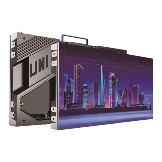
Chapter 1 Product Introduction 1.2 Cabinet Appearance Cabinet handle Upper/lower shoulder screw hole (rear maintenance) Power and signal port Telescopic structure hole LCD monitoring Left/right shoulder screw hole (front maintenance) Cabinet mounting hole Left/right shoulder screw hole (rear maintenance) Cabinet positioning column Upper/lower shoulder screw hole (front maintenance) Module... -
Page 13: Specification
Chapter 1 Product Introduction 1.3 Specification Parameter UpanelII 0.9 UpanelII 1.2 UpanelII 1.5 UpanelII1.9 Pixel composition 1R1G1B LED type 3-in-1 Black SMD Pixels per Cabinet(dots) 640x360 480x270 384x216 320x180 Cabinet size (WxHxD)(mm) 609.92x343.08x68 Aspect Ratio 16:9 Physical Material Die-casting aluminum Paramete Planeness(mm)... -
Page 14: System Solution
Chapter 1 Product Introduction 1.4 System Solution The display system consists of the LED display, sending box, control PC, matrix, splicing controller and power distribution box (refer to the shipping list for details). The following shows a topology of the system for reference: Figure 1-2 System Topology... -
Page 15: Scope Of Application
Chapter 1 Product Introduction 1.5 Scope of Application The UpanelII series products can be assembled seamlessly into a screen of any size, and are extensively used for advertisements in public places such as retail brand stores, shopping malls, hotels, banks, churches, airports, bus stations, theatres, cinemas, company lobbies, high-end clubs, museums, and large conference rooms. -
Page 16: Chapter 2 Installation And Wiring
For details about the components, refer to the shipping list. 2.2 General Installation Screen calibration is performed on the UpanelII series product before shipment, and the product needs to be installed sequentially according to the cabinet number, as... -
Page 17: Installation Of Fixed Led Display-Front Installation (Standard)
Chapter 2 Installation and Wiring 2.2.1 Installation of Fixed LED Display-Front Installation (Standard) Check whether the bottom beam is level. Make sure that its levelness is within ± 1mm. Install the cabinets sequentially from bottom to top and from middle to both sides. Fasten the adjacent cabinets with screws. - Page 18 Chapter 2 Installation and Wiring Connecting Plate (Front) Square Tube screws Bottom Beam Figure 2-2 Cabinet Fastening Upper/lower Left/right shoulder screw shoulder screw Figure 2-3 Fastening between Cabinets Figure 2-4 Front View of Cabinet Installation...
- Page 19 Chapter 2 Installation and Wiring power signal inner hexagon connected to the upper hole cabinet Figure 2-5 Front View of Power Signal Connection Between Babinets Figure 2-6 Front View of Single Cabinet Module Number...
- Page 20 Chapter 2 Installation and Wiring Figure 2-7 Front View of the Display Figure 2-8 Front Connecting Plate Figure 2-9 Front Connecting Plate (Front View) (Rear View) Figure 2-10 M8 x 70 socket head cap screws(front)...
-
Page 21: Installation Of Fixed Led Display- Rear Installation (Optional)
Chapter 2 Installation and Wiring 2.2.2 Installation of Fixed LED Display- Rear Installation (Optional) Check whether the bottom beam is level. Make sure that its levelness is within ± 1mm. Install the cabinets sequentially from bottom to top and from middle to both sides. Fasten the adjacent cabinets with screws. - Page 22 Chapter 2 Installation and Wiring Figure 2-13 Rear View of the Display Figure 2-14 Rear Connecting Plate front Figure 2-15 M10 x 60 socket head cap screws(rear)...
-
Page 23: Concave Installation(0°-2
Chapter 2 Installation and Wiring 2.2.3 Concave Installation(0°—2°) Make sure that the bottom beam is horizontal, and the value is within ± 1mm; Assemble the specific trimming cabinet from the bottom to the top and from the middle to both sides successively; The left and right cabinets are fixed with left and right shoulder screw, and the mounting plate and cabinets are fixed on the square pipe with hexagon socket bolts;... - Page 24 Chapter 2 Installation and Wiring Up/lower shoulder screw Mounting plate and socket head screws Figure 2-17 Upper and lower cabinet locked Figure 2-18 Rear Connecting Plate(front) Figure 2-19 Rear Connecting Plate...
-
Page 25: Concave Installation(≥2
Chapter 2 Installation and Wiring 2.2.4 Concave Installation(≥2°) Make sure that the bottom beam is horizontal, and the value is within ± 1mm; Assemble the cabinet from the bottom to the top, from the middle to both sides. Fix the angle block on the screw hole on the right side of the cabinet with KM2 * 6 screw, as shown in Fig. - Page 26 Chapter 2 Installation and Wiring Figure 2-22 Splicing of left and right cabinet s Angle block M6 plug bolts Figure 2-23 Internal drawing of left and right cabinet splicing...
- Page 27 Chapter 2 Installation and Wiring Figure 2-24 Splicing of left and right cabinets completed Up/lower shoulder screw Mounting plate and socket head screws Figure 2-25 Upper and lower cabinet locked...
- Page 28 Chapter 2 Installation and Wiring Figure 2-26 Rear Connecting Plate(front) Figure 2-27 Rear Connecting Plate...
- Page 29 Chapter 2 Installation and Wiring 2.2.5 Installation of Fixed LED Back Strip Installation(Optional) Back strip selection: According to the size of the display, select the corresponding back strip (2-in-1 back strip, 3-in-1 back strip, 4-in-1 back strip, 5-in-1 back strip), as shown in Figure 2- 5-in-1 4-in-1 3-in-1...
- Page 30 Chapter 2 Installation and Wiring Installation steps: 1. Install the first back strip on the wall that needs to be fixed on according to the screen size, and check whether the back strip is vertical, as shown in Figure2-29. Fig 2-29 Installing the first back strip...
- Page 31 Chapter 2 Installation and Wiring 2. Fix the positioning device on the first back strip, confirm the specific position of the second back strip, and remove the positioning device after fixing the second back strip. According to the positioning device, repeat the above steps to complete the installation of other back strips, and ensure that all back strips are vertical;...
- Page 32 Chapter 2 Installation and Wiring 3. Install the hanging pin on the cabinet, align the cabinet with the installation hole on the back strip, and hang the cabinet on the back strip. The other cabinets are then hung on the back strip from the bottom to the top, from the middle to the sides. This is shown in Figure2-32,2-33,2-34.
- Page 33 Chapter 2 Installation and Wiring 4. If there are multiple rows of back strip to install, when installing the next row, you need to install the connector on the first back strip of the previous row, so as to confirm the position of the first back strip of the next row, connect the upper and lower back strips and ensure that the upper and lower back strips are on the same vertical line, and then repeat the above steps to complete the installation of other back strips and ensure...
- Page 34 Chapter 2 Installation and Wiring 5. The installation of the back strip depends on the size of the cabinet. Different cabinet sizes have different mounting distances in the center of the back strip. Note: Confirm the array of the back strip according to the drawing of the order, the above array is for reference only.
-
Page 35: Module Flatness Adjustment
Chapter 2 Installation and Wiring 2.3 Module Flatness Adjustment 2.3.1 Module Flatness Adjustment When there is a deviation in flatness between adjacent modules, use the adjustment tool to adjust the magnet on the box. At the low end, the module regulates the adjustable magnets until the module is flush with the adjacent modules. -
Page 36: Wiring For Led Display
Chapter 2 Installation and Wiring Adjusting tool Adjustable magnet Figure 2-40 Schematic diagram of module flatness adjustment 2.4 Wiring for LED Display 2.4.1 Common Cables Incoming Power and DVI Cable USB Cable signal Cable Signal Cable Passing Incoming Signal Cable Through Cabinet... -
Page 37: Signal Cable Connection
Figure 2-41~ Figure 2-44 shows the signal cable connection for display with a resolution of 1920 x 1090. Signal cables shall be connected based on the wiring diagram of the delivered products for the project. Figure 2-41 Signal Cable Connection Diagram of UpanelII 0.9 Figure 2-42 Signal Cable Connection Diagram of UpanelII 1.2... - Page 38 Chapter 2 Installation and Wiring Figure 2-43 Signal Cable Connection Diagram of UpanelII 1.5 Figure 2-44 Signal Cable Connection Diagram of UpanelII 1.9...
-
Page 39: Power Cable Connection
Figure 2-45 ~ Figure 2-48 shows the power cable connection for display with a resolution of 1920 x 1090.Power cables shall be connected based on the wiring diagram of the delivered products for the project. Figure 2-45 Power Cable Connection Diagram of UpanelII 0.9 Figure 2-46 Power Cable Connection Diagram of UpanelII 1.2... - Page 40 Chapter 2 Installation and Wiring Figure 2-47 Power Cable Connection Diagram of UpanelII 1.5 Figure 2-48 Power Cable Connection Diagram of UpanelII 1.9...
-
Page 41: Smart Control Distribution Box
Chapter 2 Installation and Wiring 2.4.4 Smart Control Distribution Box The Smart Control Distribution Box can be used for distributing electric power to the LED display, and has the function for real-time monitoring of the temperature, humidity, smoke, and mains voltage of the external environment. The control software has the scheduled start/stop function, allowing you to set any time for the LED display to be remotely started or stopped. - Page 42 Chapter 2 Installation and Wiring PLC connection of the smart control distribution box: The PLC communication system is RS485, It uses converter from control computer RS232 to RS485. For more detail information, please refer to our Intelligent Power Distribution Management System Manual. Figure 2-50 Distribution Box PLC Connection Diagram...
-
Page 43: Chapter 3 Led Display Control Setting
Chapter 3 LED Display Control Setting Chapter 3 LED Display Control Setting 3.1 Power-on Testing Before performing control setting on the LED display, confirm that each device is connected correctly. Before turning on the power of the LED display, you must use a multimeter to test the live wire, neutral wire, and ground wire of the AC power supply, in order to ensure they are not conductive with each other. -
Page 44: Preparation
Chapter 3 LED Display Control Setting 3.2 Preparation 3.2.1 Starting the Hardware Start the control PC Windows system. After the graphics card driver is activated, set graphics card of the control PC to replication mode and confirm that the green indicator of the sending box is blinking normally (blinking once per second). -
Page 45: Display Configuration
Chapter 3 LED Display Control Setting 3.3 Display Configuration Run UniLCT-Mars. Make sure that Control System on the main window is 1. Click the User option and select Advanced Login, as shown in Figure 3-3: Figure 3-3 Main Window of UniLCT-Mars Enter the initial password “admin”, as shown in Figure 3-4, to go to the advanced user window. - Page 46 Chapter 3 LED Display Control Setting Figure 3-6 Screen Config The following window is displayed. Set Sending Board Resolution (1920×1080 recommended). Set Graphics Output Resolution to the same value as Sending Board Resolution. Then click Save to save the settings. Figure 3-7 Sending Board Configuration...
- Page 47 Chapter 3 LED Display Control Setting After configuring the parameters on the Sending Board page, click Scan Board to display the following window: Figure 3-8 Scan Board Configuration Click Load File to load the file xxxx.rcfg stored in the optical disk. Click Send To HW.
- Page 48 Chapter 3 LED Display Control Setting After configuring the parameters on the Scan Board page, click Screen Connection to display the following window: Click Read File to load the file xxxx.scr stored in the optical disk, as shown in Figure 3-9. Figure 3-9 Screen Connection 1...
-
Page 49: Brightness Adjustment
Chapter 3 LED Display Control Setting Click Send To HW. After sending, confirm that the screen is complete. Then click Save. Figure 3-10 Screen Connection with Loaded File 3.4 Brightness Adjustment On the main window, click Brightness, as shown in Figure 3-11, to display the brightness adjustment interface: Figure 3-11 Main Window for Advanced User... - Page 50 Chapter 3 LED Display Control Setting There are four brightness adjustment modes, namely Manual, Schedule, Auto, and Auto Adjustment by Hardware. After adjustment is finished, click Save to HW to save the adjustment results to the hardware. Manual Adjustment Select Manual and adjust the brightness by dragging the scroll bar below Brightness Adjustment or directly modifying the brightness value (the maximum value is 255) next to the scroll bar.
-
Page 51: Correction Coefficient Management
3.5 Correction Coefficient Management The UpanelII series products have been subject to correction before shipment. To ensure the optimum displaying effect of the screen, you need to activate the correction function when using the LED display, and to reload the correction coefficients after replacing the modules or scan board. - Page 52 Chapter 3 LED Display Control Setting Configure Enable/Disable Calibration to Brightness, click Save, and then click Manage Coefficients to display the following window: Figure 3-14 Manage Coefficients Upload coefficients: Upload the correction coefficient database generated by the software or read back by the display screen to the screen. Save coefficients to database: Read back and save the coefficients from the screen to the coefficient database.
-
Page 53: Setting Coefficients For A New Receiving Card
Chapter 3 LED Display Control Setting 3.5.1 Setting Coefficients for a New Receiving Card 1) As shown in Figure 3-15, select Topology or List. Select the position of the replaced receiving card. Click Next: Figure 3-15 Selecting Area for New Receiving Card 2)... - Page 54 Chapter 3 LED Display Control Setting Select the corresponding correction coefficients: Figure 3-17 Selecting Correction Coefficients for Receiving Card Select Stable Upload and click Next: Figure 3-18 Uploading Correction Coefficients...
- Page 55 Chapter 3 LED Display Control Setting Adjust Coefficient: Perform a simple adjustment if the displaying effect is not good enough after you upload the coefficient. Then click Next. Figure 3-19 Simple Adjustment Red:Adjust the red brightness value of calibration coefficients. Green:Adjust the green brightness value of calibration coefficients.
-
Page 56: Setting Coefficients For A New Module
Chapter 3 LED Display Control Setting 3.5.2 Setting Coefficients for a New Module Select Position of the New Module: Select Topology or List. Then select the position of the receiving card where the new module is located. Double click the selected position: Figure 3-21 Selecting Cabinet for the New Module... - Page 57 Chapter 3 LED Display Control Setting Choose Display Mode to Modules. Select the position of the new module and click Next. Figure 3-22 Selecting Position of New Module Module Size:Set the size of the module in a cabinet. The software determines each module arrangement based on module size and cabinet size.
- Page 58 Chapter 3 LED Display Control Setting Save the correction coefficients to the hardware (Use similar steps in setting coefficients for a new receiving card. For details, refer to Step 4, Step 5, and Step 6 in Section 3.5.1) so that they are retentive after a power failure. Figure 3-23 Obtaining Correction Coefficients for a New Module...
-
Page 59: Pre-Storing Picture
Chapter 3 LED Display Control Setting 3.6 Pre-storing Picture On the Prestore Picture interface, you can save a picture as the prestored picture for the screen. This prestored picture can be set as a screen displayed upon booting, signal cable disconnection, or DVI signal absence. On the main window, click Tool and select Prestore Picture, as shown in Figure 3-24. - Page 60 Chapter 3 LED Display Control Setting 1) Prestore Picture Settings Select Picture: Click Browse to select the directory of the picture. Screen Effect: Set the selected picture to be displayed on the whole screen by means of stretching, tiling, or centering. Cabinet Effect: Set the selected picture to be displayed on each cabinet of the screen by means of stretching, tiling, or centering (the number of pictures displayed by each cabinet shall be equal to the number of receiving cards in the cabinet).
-
Page 61: Dehumidification Mode
Chapter 3 LED Display Control Setting 3.7 Dehumidification Mode In the main window, click "Tools" - "SD600E Dehumidification" to enter the dehumidification interface. Figure 3-25 Dehumidification Setting Select the corresponding dehumidification module and click “Settings” to enter the corresponding dehumidification mode. Figure 3-26 Dehumidification Interface... -
Page 62: Mdc Function
Chapter 3 LED Display Control Setting There are three dehumidification mode levels, and the dehumidification time corresponding to different dehumidification levels is different. Exit the dehumidification mode and select the normal mode. The default brightness value is 60% after exiting the dehumidification mode. -
Page 63: Mdc Mode Loading Ways
Chapter 3 LED Display Control Setting 3.8.1 MDC mode loading ways In the main window, click "Tools" - "Controller Cabinet Configuration File Import" to enter the configuration file import controller interface. Figure 3-27 Controller Cabinet Configuration File Import Select the configuration file to be imported to the controller, click "Add Configuration File"... - Page 64 Chapter 3 LED Display Control Setting Through "Refresh Configuration File", you can see whether the configuration file is saved to the device successfully in real time. Figure 3-29 Refresh Configuration File After the configuration file is stored in the controller, click "Apply Configuration File" to send it through the software.
-
Page 65: Mdc Mode Switching Ways
Chapter 3 LED Display Control Setting Wait for the software to prompt that the application is successful, that is, the configuration file is sent successfully, and complete the different MDC mode switching. 3.8.2 MDC mode switching ways Quickly software switching In the main window, click "Tools"... - Page 66 Chapter 3 LED Display Control Setting Quickly hardware switching Operate through the front panel of the sending box, " Press knob " - " Advanced Settings " - " Load RCFG Files " - " Select mode switch " - " Save to RV Card ". Enter the following screen.
-
Page 67: Chapter 4 Led Display Playing Setting
Chapter 4 LED Display Playing Setting Chapter 4 LED Display Playing Setting 4.1 Selecting a Playing Solution The playing software UniStudio has three playing modes, namely Simple playing program, Professional playing program, and Priority programs of the page. Professional playing program is used most commonly. This Section introduces the Professional playing program only. -
Page 68: Playing Setting
Chapter 4 LED Display Playing Setting 4.2 Playing Setting 4.2.1 Display Window Setting Run the UniStudio, click Settings and select Display Setting, as in following fig: Figure 4-3 Display Window Setting Number of Display Windows: Indicates the number of display windows. To increase or decrease the number of display windows, re-enter the number of display windows in the box next to Number of Display Windows and then click Update. -
Page 69: Startup Setting
Chapter 4 LED Display Playing Setting 4.2.2 Startup Setting On the main window of the software, click Setting > Start Setting to enable the software to run automatically upon startup of the PC and to automatically activate a playing solution. See Figure 4-4: Figure 4-4 Startup Setting Auto Run after Power-on: If you enable this function, UniStudio will run automatically the next time when the PC is started. -
Page 70: Editing Professional Playing Solution
Chapter 4 LED Display Playing Setting Enable Auto Play: If you enable this function and specify a playing solution for the screen, the software will automatically activate the specified playing solution once the software is started. Instant plug and play of USB disk: If you enable this function, the PC will automatically read and activate the playing solution once the USB flash drive is inserted to the PC. - Page 71 Chapter 4 LED Display Playing Setting After adding a general time segment or interstitial segment, click General Segment 1 to edit the properties displayed in the segment editing area on the right side, as shown in Figure 4-6: Figure 4-6 Properties of General Time Segment...
-
Page 72: Editing The Program Page
Chapter 4 LED Display Playing Setting 4.3.2 Editing the Program Page Creating a program page As shown in Figure 4-7, right click General Segment or click the Add Program Page button in the toolbar to create a program page: Figure 4-7 Creating a Program Page... - Page 73 Chapter 4 LED Display Playing Setting Setting the properties After creating the program page, click Program 1 and set the background, displaying mode, and other properties displayed on the property page on the right side. See Figure 4-8: Figure 4-8 Properties of Program Page If you select Specify Number of Times, the next general program page is played after the preset Times to Play for the display window with the longest playing time on the current program page has been reached.
- Page 74 Chapter 4 LED Display Playing Setting When the current program page is played, the background picture or colour of the program page is displayed in the area not covered by the display window, as shown in Figure 4-9: Figure 4-9 Background of Program Page After adding the program page, you can move, copy, paste, or delete the program page by using the toolbar in the program page editing area, or by using the short-cut menu, as shown in Figure 4-10.
-
Page 75: Editing The Display Window
Chapter 4 LED Display Playing Setting 4.3.3 Editing the Display Window Adding a display window After adding a program page, you need to add a display window to this program page. Click Add Window on the toolbar of the program page to add a window to the current program page. - Page 76 Chapter 4 LED Display Playing Setting Setting the location and size of the display window The location and size of the new window is generated randomly and can be adjusted based on actual conditions by using either of the following two methods: Directly specify the new location and size in the setting pane, as shown in Figure 4-13: Figure 4-13 Setting the Window Size...
- Page 77 Chapter 4 LED Display Playing Setting Deleting a display window Select the window to be deleted. Click the delete key to delete the window, as shown in Figure 4-15: Figure 4-15 Deleting the Display Window Moving a display window Select the program or window. Click the direction key to adjust the playing sequence, as shown in Figure 4-16: Figure 4-16 Moving a Display Window...
-
Page 78: Editing The Media
Chapter 4 LED Display Playing Setting 4.3.4 Editing the Media Adding the media The type of window for adding the media is Common Window. Click the Add Media button of a common window to select media of different types to be added into the media list. - Page 79 Chapter 4 LED Display Playing Setting After adding the media, you can set the media texts and properties, as shown in Figure 4-18. Figure 4-18 Media Setting Window Setting the media properties Different media have different properties. After a medium in the media list is selected, the property page of this medium is displayed below the selected medium.
- Page 80 Chapter 4 LED Display Playing Setting In an actual application, if different playing times are required for different media, you can select the media in the media list and then double click times to play to modify the playing times by either entering a new value or selecting a value from the drop-down list.
- Page 81 Chapter 4 LED Display Playing Setting Right click the media to perform operations on the selected media, as shown in Figure 4-21: Figure 4-21 Media Operation Menu Right click a blank area in the media playlist. A media playing menu is displayed, as shown in Figure 4-22: Figure 4-22 Media Playing Menu...
-
Page 82: Playing The Media
Chapter 4 LED Display Playing Setting 4.3.5 Playing the Media After the playing mode is edited or loaded, click the play key on the main toolbar to start the current playing mode, as shown in Figure 4-23: Figure 4-23 Play Key on the Toolbar After play is activated, the editing page is switched to the playing page, as shown in Figure 4-24: Figure 4-24 Play Information Page... - Page 83 Chapter 4 LED Display Playing Setting Clicking Pause or Stop on the toolbar can pause or stop the currently played program. You can also perform this operation by using the operation menu that appears when you right click the display window. See Figure 4-25: Figure 4-25 Short-cut Menu All display windows on the same program page plays simultaneously.
-
Page 84: Saving And Opening A Playing Solution
Chapter 4 LED Display Playing Setting 4.4 Saving and Opening a Playing Solution Save: After a playing solution is created, you can click Schedule on the toolbar and select Save or Save As to save the playing solution in the format of xxxx.plym. See Figure 4-27: Figure 4-27 Saving a Playing Solution File Open: After a playing solution is saved, you can directly click Schedule in the toolbar... -
Page 85: Chapter 5 Startup, Shutdown, And Maintenance
Chapter 5 Startup, Shutdown, and Maintenance Chapter 5 Startup, Shutdown, and Maintenance 5.1 Startup Sequence Start the distribution box for the LED display. Start the control computer. Start the video processor. Start the sending box. Screen color will reach to best status after 5 minutes lighting up.(Color gradually changes as the temperaure warms up ) 5.2 Shutdown Sequence Shut down the video processor. -
Page 86: Warm-Up Operation
Chapter 5 Startup, Shutdown, and Maintenance 5.4 Warm-up Operation If the LED display has been idle for a long period of time, perform warm-up operations before using the LED display. Set the prestored picture as follows when you initially start the LED display. This setting is for warm-up operation only. You do not need to set the prestored picture if the LED display is used frequently. -
Page 87: Ageing
Chapter 5 Startup, Shutdown, and Maintenance 5.4.2 Ageing On the main window, click Brightness to enter the brightness adjustment interface, as shown in Figure 5-2: Figure 5-2 Main Window for Advanced User Select Manual and set the brightness to 26 (the brightness is about 10%) by dragging the scroll bar below Brightness Adjustment. -
Page 88: Display Brightness And Ageing Time Table
Chapter 5 Startup, Shutdown, and Maintenance Return to the main window. Click Display Control to enter the Screen Control interface. Set Self Test to White. Click Send to finish the operation. As showed in Figure 5-4 and Figure 5-5. Figure 5-4 Display Control Fig 5-5 Display Control 5.4.3 Display Brightness and Ageing Time table Adjust the screen brightness and perform ageing based on the steps described in... -
Page 89: Chapter 6 Troubleshooting And Component Replacement
Chapter 6 Troubleshooting and Component Replacement Chapter 6 Troubleshooting and Component Replacement 6.1 Common Faults and Troubleshooting Methods 6.1.1 Failure in Lighting up the Display Causes: No power is supplied to the display or the control devices. The LED display does not have input signals. The control PC is in sleep mode or the graphics card is set incorrectly. -
Page 90: Screen Blinking
Chapter 6 Troubleshooting and Component Replacement 6.1.3 Screen Blinking Causes: The ports on the sending box are loose, or the signal cables are too long. The output resolution of the playing device or sending box is set incorrectly. Troubleshooting method: Check whether the DVI cable and signal cable are connected to the display and devices, or whether the length of signal cables exceeds the maximum transmission distance (the effective transmission distance shall not exceed 10 m for DVI cable,... -
Page 91: Failure In Lighting Up Part Of The Modules In The Cabinet
Chapter 6 Troubleshooting and Component Replacement 6.1.6 Failure in Lighting up Part of the Modules in the Cabinet Causes: Output of the power supply for the modules is faulty. Output of signal which controls the related modules is faulty. Troubleshooting method: Check DC voltage for the modules. -
Page 92: Replacement Of Power Supply
Chapter 6 Troubleshooting and Component Replacement 6.2.2 Replacement of Power Supply Replace a power supply of the LED display based on the following steps: Step Picture Description Locate the faulty cabinet, cut off the power supply Remove the module of the faulty cabinet and remove the HUB card. -
Page 93: Replacement Of Receiving Card
Chapter 6 Troubleshooting and Component Replacement 6.2.3 Replacement of Receiving Card Replace receiving card of the LED display based on the following steps: Step Picture Instruction Operation Locate the faulty cabinet, cut off the power supply Remove the module of the faulty cabinet Remove the fixed screws of the receiving card. -
Page 94: Replacement Of Hub Card
Chapter 6 Troubleshooting and Component Replacement 6.2.4 Replacement of HUB Card Replace receiving card of the LED display based on the following steps: Step Picture Instruction Operation Locate the faulty cabinet, cut off the power supply Remove the module of the faulty cabinet Remove the fixed screws of the HUB card. -
Page 95: Chapter 7 Packaging Transportation And Storage
Chapter 7 Packaging Transportation and Storage 7.1 Packaging The UpanelII series products would be packed in carton, and the carton is vacuum- packed in an anti-static bag, and finally packed in heavy-duty carton, as shown below: Figure 7-1 Package in Carton Figure 7-2 Package in Heavy-Duty Carton 7.2 Transportation... -
Page 96: Chapter 8 After-Sales And Warranty
If factory repair service is needed, customer shall bear the freight, insurance, tariff and customs clearance for return delivery of the returned products or parts to Unilumin’s service station. And Unilumin will send back the repaired products or parts to customer... -
Page 97: Disclaimer
Unilumin believes the condition is necessary, on-site engineer service free of charge will be provided. In this case, customer shall provide a fault report to Unilumin for on- site service application. The content of the fault report shall include but not limited to photos, videos, number of faults, etc., to enable Unilumin to conduct preliminary fault... -
Page 98: Warranty Service Process
Unilumin with warranty card or contract number. Specific content of the service and contact information shall be provided. Product Return to Repair Process: Submit service requirements through the website, email, telephone and other service channels of Unilumin with warranty card or contract number. Packing list of the... -
Page 99: Other
8.6 Other This Warranty Policy is a standard application of Unilumin. No other third party (including any agent, distributor or sales representative) is authorized to make any representations or warranties that are different from this Warranty Policy. Unless... -
Page 100: Product Warranty Card
Chapter 8 After-Sales and Warranty 8.7 Product Warranty Card Product Warranty Card Warranty Order No. Shipment Date Period Product Product Model Quantity Customer Contact Name Information Customer Address: Remark(s): Warranty Record Completion Signature of Warranty Date Fault and Troubleshooting Date Customer... -
Page 101: Attachment 1 - Path Of Signal Cable Inside The Cabinet
Attachment 1 – Path of Signal Cable inside the Cabinet Attachment 1 - Path of Signal Cable inside the Cabinet Receiving card Signal Cable Connection Diagram (Front View) of UpanelII Series... -
Page 102: Contact Information
Shenzhen. Daya Bay manufacturing center: Longsheng Fifth Road, western Daya Bay, Huiyang District, Huizhou. Telephone (switchboard): + 86- (0) 755-29918999 Fax: + 86- (0) 755-29912092 Website: www.unilumin.com Service Department Tel: + 86- (0) 755-29592226 (direct line) 24-hour service hotline: 400-677-3888...
Need help?
Do you have a question about the UpanelII and is the answer not in the manual?
Questions and answers