Table of Contents
Advertisement
Advertisement
Table of Contents

Related Manuals for Unilumin Upad III


Summary of Contents for Unilumin Upad III
- Page 2 UpadIII product manual Revision History Version Updated description Date Initial Edition First published 2015.08.31 Second Edition Optimized display structure 2016.11.14 Specifications and Contents are subject to change without notice. www.unilumin.cn...
- Page 3 Copyright Copyright © 2016 Unilumin Group Co., Ltd. All rights reserved. The operating software is based on Windows System. All brand, product, service names and logos are trademarks and registered trademarks of their respective owners and are hereby recognized and acknowledged.
- Page 4 Display may be much more likely to fail and has shorter lifespan when installed at seaside, saline, sulfur-containing gases zone, kitchen exhaust or some area which has a high temperature difference between outside and inside. If inevitable, please contact with our service network for professional advice. www.unilumin.cn...
- Page 5 It may cause the device prone to failure and shorten service life when installed at seaside, saline, sulfur-containing gases zone, kitchen exhaust or some area have a high temperature difference between outside and inside. When it is inevitable, please contact with our service network professionals. www.unilumin.cn...
-
Page 6: Table Of Contents
RIGHTNESS ETTING 3.5 C ....................... 25 ALIBRATION 3.5.1 Set Coefficients for a New Scan Board (Receiving Card) ......27 3.5.2 Set Coefficients for a New Module ..............30 3.6 P ....................32 RESTORE ICTURE 4. DISPLAY PLAY-SETTING ..................34 www.unilumin.cn... - Page 7 6.1.6 Certain Row of the Module or Individual Module Does Not Light ....54 6.2 M ................. 55 ARTS EPLACEMENT 6.2.1 Module Replacement for Indoor Product ............55 6.2.2 Power Supply and Receiving Card Replacement for Indoor Product .... 57 6.2.3 Module Replacement for Outdoor Product ............ 60 www.unilumin.cn...
- Page 8 7. PACKAGE TRANSPORTATION AND STORAGE ..........66 7.1 P ......................66 ACKAGE 7.2 T ....................66 RANSPORTATION 7.3 S ......................66 TORAGE FIGURE 1: PRODUCT WARRANTY CARD ............67 FIGURE 2: PATH OF SIGNAL CABLE INSIDE THE CABINET ......68 www.unilumin.cn...
-
Page 9: Product Introduction
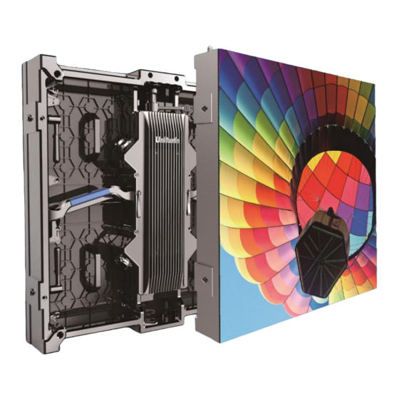
Seamless splicing for concave and convex, support flexible splicing between concave 5° and convex 10°. 1.2 Cabinet Appearance 9.Screw hole 1.Hanging latch 10.Bottom magnet 2.Top magnet 3.Cabinet handle 11.Locking plate 12.Edge protection pin 4.Locating pin 5.Signal socket 13.Left-right lock 6.Cabinet handle 7.Power socket 8.Angle block Fig 1-1【Cabinet appearance】 www.unilumin.cn... -
Page 10: Specification
2000-9300 adjustable parameter Contrast ratio 5000:1 Viewing Angle(° ) 140/120 Input voltage AC 100~240 Electrical Input frequency(Hz) 50~60 parameter Input power 120/40 <max/typical >(W/panel) Storage temperature and -20~+55/10~80% humidity(℃/RH) Circumstance Operation temperature and parameter -10~+45/10~80% humidity(℃/RH) Ingress protection IP30 www.unilumin.cn... -
Page 11: Outdoor Product Specification
Contrast ratio 5000:1 3000:1 Viewing Angle(° ) 140/120 Input voltage AC 100~240 Input frequency (Hz) Electrical 50~60 parameter Input power 240/80 210/70 <max/typical >(W/panel) Storage temperature and -30~+60/10~90% humidity(℃/RH) Circumstance Operation temperature parameter -20~+50/10~90% and humidity(℃/RH) Ingress protection IP65 www.unilumin.cn... -
Page 12: Application
UpadIII product manual 1.4 Application UpadIII can be widely used in indoor stage background, senior auto show, peak BBS, exhibition display, advertising, theatrical performances and other public places. www.unilumin.cn... -
Page 13: Installation And Wiring
4) Fixed the cabinets against to the back frame with plate; 5) According to the actual situation of the installation site, sometime the sandbags and other balance weight need to be pressed on the ground beam support. www.unilumin.cn... - Page 14 UpadIII product manual Fig 2-1【Floor Installation】 www.unilumin.cn...
- Page 15 UpadIII product manual Operation of hoisting installation Step Picture Instruction Operation No.1 Open lock plate to left Pull up the occlusion and No.2 switch to left Switch the lock plate to No.3 switch inside Hand shank switch right to No.4 www.unilumin.cn...
- Page 16 UpadIII product manual Operation of Left-right Connection Step Picture Instruction Operation Handle Keep hand shank up then No.1 push to left edge Switch handle Switch hand shank to No.2 horizontal Switch down the hand No.3 shank No.4 Fasten finish www.unilumin.cn...
-
Page 17: 2Hositing Installation
2.2.2Hositing installation Adjust the steel wire rope to keep hanging beam level, to prevent the display tilt; Fig 2-2【Fix Hanging Beam】 Install first horizon cabinets Mid to L-R side in turn; Fig 2-3【Install Cabinets】 Fig 2-4【Install Horizon Cabinets First】 www.unilumin.cn... - Page 18 UpadIII product manual Fix other cabinets Mid to L-R,Up to Down (Note: no limitation for display width, the maximum height is 20 set cabinets.). Fig 2-5【Whole Led Display】 www.unilumin.cn...
-
Page 19: Product Wiring
【Input AC Power Cable】 【Power Cable between 【Signal Input Cable】 Cabinets】 【Signal Cable between 【DVI Cable】 【USB Cable】 Cabinets】 Indoor: 【Input AC Power Cable】 【Power Cable between 【Signal Input Cable】 Cabinets】 【Signal Cable between 【DVI Cable】 【USB Cable】 Cabinets】 www.unilumin.cn... -
Page 20: Signal Wiring
UpadIII product manual 2.3.2 Signal Wiring The following signal connection diagram is 6(w)*4(h)cabinets arrangement, which is specific on actual project. Fig 2-8【Signal Wiring Diagram】 www.unilumin.cn... -
Page 21: Power Wiring
UpadIII product manual 2.3.3 Power Wiring The following signal connection diagram is 6(w)*4(h)cabinets arrangement, which is specific on actual project. Fig 2-9【Power Wiring Diagram】 www.unilumin.cn... -
Page 22: Flight Distribution Box Show
Varieties of control modes: manual control, automatic timing control, PLC intelligent control. www.unilumin.cn... - Page 23 UpadIII product manual Fig 2-10【Power Distribution Box Schematic】 Distribution parts name name note Input plug Receive power Output plug Supply power Master switch Control main power on or power off Air switch Control branch power on or power off www.unilumin.cn...
-
Page 24: Display Control-Setting
Start up computer, log on the Windows system. Set up the graphic card at duplication model after boot-up. Check the indicator light of the sending card. (the green indicator light twinkle normally, once per second) 【 】 Fig 3-1 Duplication Model www.unilumin.cn... -
Page 25: Software Installation
Note: Please follow on display instruction to complete each software installation. Fig 3-2 【 Software Installation 】 3.3 Display Setting Run UniLCT-Mars, ensure that the interface “Control system” is “1”. Then click "User" ,select "Advanced User Login", as in following fig: Fig 3-3 【Log in Interface】 www.unilumin.cn... - Page 26 Input initial password "666" to get into Advanced User Login interface, as in following figure: Fig 3-4 【Password】 After logged in, click "Screen Config" at the main interface, as in following figure. Fig 3-5【Main Interface】 Click the "Next" into next step. Fig 3-6【Screen Config】 www.unilumin.cn...
- Page 27 UpadIII product manual Pop up the following window, set up sending card resolution which is supposed to be the same as the computer graphics output (recommend resolution 1920*1080),click "Save" after setting. Fig 3-7【Sending Board Config】 www.unilumin.cn...
- Page 28 After finishing the Sending Card setting, save it and then click "Receiving Card", as in following figure: Click "Load from File", then choose the file "xxx.rcfg" in the CD. Click "Send to Receiving Card". Make sure every receiving card works normally, after that, please click "Save". Fig 3-8【Receiving Card Config】 www.unilumin.cn...
- Page 29 After the Receiving Card setting, Click "Screen Connection", as in following fig: Fig 9【Screen Connection 1】 Click "Load from File", then choose the file "xxxx.scr" in the CD. Click "Send to HW". Make sure the whole LED display is working normally, after that, please click “Save”. Fig 3-10【Display Connection 2】 www.unilumin.cn...
-
Page 30: Brightness Setting
Fig 3-11【Main Interface】 Brightness adjustment has three options, Manually Adjustment, schedule adjustment or Automatically Adjustment. After adjustment, please click "Save to Hardware". 1. Manually Adjustment After adjusting brightness value, click "Save to Hardware" for save the setting. Fig 3-12【Manually Brightness Adjustment】 www.unilumin.cn... - Page 31 Select "Schedule" in the "Adjustment Mode" panel to open schedule adjustment page. Schedule adjustment is to generate a time table and the LED display brightness, Gamma, color temperature and brightness mode will be adjusted according to the time table, as in following fig: Fig 3-13【Schedule Brightness Adjustment】 www.unilumin.cn...
- Page 32 The "Enable Bright Mode" option can be selected only when the "Bright Mode Table" is configured in the "Manual Adjust Page". Automatically Adjustment Not recommended to use automatically adjustment. If you want to active this function, please click "Automatically Adjustment" then follow on display instruction to complete the setting. www.unilumin.cn...
-
Page 33: Calibration
LED Module or a Receiver Card, we strongly recommend you use UniLCT-Mars software to update the new calibration coefficients for maintain a good uniformity. Click “Calibration” at the main interface, as in following figure. Fig 3-15【Main Interface】 www.unilumin.cn... - Page 34 Adjust Coefficients: Fine tune the calibration coefficients for better performance. Erase or reload Coefficients: Erase or reload the calibration coefficients on selected section of LED display. Reset Calibration Coefficients: Reset the calibration coefficients on whole or selected section of LED display. www.unilumin.cn...
-
Page 35: Set Coefficients For A New Scan Board (Receiving Card)
1) First choose "Topology or List" function, select the new replaced receiving card section, as in following figure. Fig 3-17【Selecting the Section of New Receiving Card】 2) Click "Next", select coefficients source from database, then click "Browse". Fig 3-18【Select Coefficients from Database】 www.unilumin.cn... - Page 36 UpadIII product manual 3) Choose the right calibration cofficient of new receiving card,as in following figure. Fig 3-19【Select the Right Calibration Coefficient】 Select"Stable Upload", then click "Next", as in following figure. Fig 3-20【Upload Calibration Coefficients】 www.unilumin.cn...
- Page 37 Red:Adjust the red brightness value of calibration coefficients. Green:Adjust the green brightness value of calibration coefficients. Blue:Adjust the blue brightness value of calibration coefficients. Save calibration coefficients to hardware, so it won’t be lost when the LED display powers off. Fig 3-22【Save Calibration】 www.unilumin.cn...
-
Page 38: Set Coefficients For A New Module
Set up the size of a module here, when it’s done, find out and select the position of the new module; Fig 24【Select module section on cabinet】 Module Size:First set up the size of a module here, when it’s done, find out and select the position of the new module. www.unilumin.cn... - Page 39 Coefficient adjustment (similar to new receiving card coefficient, please refer to 3.5.1, step2, 3). Save the calibrated coefficient in the hardware (in case of losing when power off, please refer to 3.5.1, step 4, 5, 6). Fig 3-25【Select Calibration Coefficients from New Receiving Card or Module】 www.unilumin.cn...
-
Page 40: Prestore Picture
3.6 Prestore Picture The LED display will show Prestore picture when boot display up, signal cable disconnect and no DVI signal input. Please click "Tools", select "Prestore Picture", as in following figure: Fig 3-26【Prestore Picture】 Fig 3-27【Prestore Picture Settings】 www.unilumin.cn... - Page 41 No DVI Signal: Set up the display output when no DVI signal. Click "Send", send function settings to the hardware. (If no save to hardware, the settings will lost after power off.) Click "Save to Hardware", save Function Settings to the hardware. (the settings will not lost after power off) www.unilumin.cn...
-
Page 42: Display Play-Setting
Priority program of the page, "professional broadcast program" mode mostly used, in this chapter only for introducing "professional broadcast program" mode. Run Unistudio, click "Settings", select "switch broadcast scheme mode", in the edit mode setting interface, select "professional broadcast scheme" and click "ok". Fig 4-1【Choose Play Mode】 Fig 4-2【Edit Mode Setting】 www.unilumin.cn... -
Page 43: Playing Setting
"update". Start X: The horizontal start point of the display window. Start Y: The vertical start point of the display window. Width: horizontal pixels of display. Height: vertical pixels of display. Other options are set by default. www.unilumin.cn... -
Page 44: Start Setting
Auto Play: Preset the schedule play file, and the software will play the file automatically when start up. USB Disk play: the control computer will read playlist and play automatically from USB drive. www.unilumin.cn... -
Page 45: The Edit Of A Professional Broadcast Scheme
Fig 4-5【Create A New Program of Page】 Editing Properties of Segment After Adding the regular session or emergency call period, we can edit its properties in time on the right side of the editor area. Fig 4-6【Editing Properties of Segment】 www.unilumin.cn... -
Page 46: Editing Program Page
Fig 4-7【Add New Segment】 Set up Properties After adding program pages, the right side of the page is attributes, we can set up programs broadcast, playback mode and other properties, as in following fig: Fig 4-8【Show Page Properties】 www.unilumin.cn... - Page 47 Fig 4-9【Program Background】 After adding program , one can use "show page editing area" in the toolbar or right-click menu page for the program moving, copying, pasting and deleting operations. Fig 4-10【Operating Menu of Show Page】 www.unilumin.cn...
-
Page 48: Editing Window
"add window", you can add the window to the current page. Fig 4-11【Addition Page】 After finishing adding the window page, the added window will be selected, and the display window will display the current added window. Fig12【Added Window】 www.unilumin.cn... - Page 49 These values can be reset directly by using 2 ways as follow: Set the new position and size directly, as in follow fig: Fig 4-13【Tools for Window Position and Size Setting】 Click the play window and adjust with the mouse Fig 4-14【Adjustment with the Mouse】 www.unilumin.cn...
- Page 50 To delete a specified window, click the circled delete button, as in following fig: Fig 4-15【Delete Window】 Move Select the desired program or window, click the arrow keys to move the position, adjust the playback order, as in following fig: Fig 4-16【Move window】 www.unilumin.cn...
-
Page 51: Editing Media
Fig 4-17【Add A Scrolling Text Window】 Add media Media sources of a media type that is supported by Unistudio can be added to a common window for showing. Click the circled button to access the drop-down menu of media types. Fig 4-18【Add A Media】 www.unilumin.cn... - Page 52 Select the media in the list, then double click the "Play Time Grid" to change the play times: You can manually enter a new number or select the existing number in the pull-down lists, as in following fig: Fig 4-20【Change Play Times of Media】 www.unilumin.cn...
- Page 53 UpadIII product manual Apply the media properties to others Select media, and then click right button of mouse and choose the media to apply to in the pop up dialog. Fig 4-21【Apply properties to media】 www.unilumin.cn...
-
Page 54: Playing
( if there is), next breaking info( if there is ), as in following fig: Fig 4-23【Play page】 Click "Pause" and "Stop" button on the toolbar to pause or stop play. You also can use the right-click menu on the display as in following fig: www.unilumin.cn... - Page 55 "Play". If the clock is transparent, the moving program will play, The clock will be superimposed on the media in the common window, the display performance as in the following fig: Fig 4-25【Clock Transparent Overlay Performance】 www.unilumin.cn...
-
Page 56: Save And Open
"Save" or "Save As", the saved file format is "xxx. plym", as in following fig: Fig 4-26【Save Document】 After saving broadcast scheme, we can click the "play" directly through the menu toolbar next time, then choose "Open", as in following fig: Fig 4-27【Open directly】 www.unilumin.cn... -
Page 57: Display On / Off Step And Maintenance
Ensure to clean the display carefully using a antistatic soft brush to prevent scratches every month; Inspect the devices and cable is tied on Power Distribution Box and make sure connected to earth by quarterly; Inspect the display structure frame every year. www.unilumin.cn... -
Page 58: Maintenance Method If Not Using For A Long Time
"Cable Disconnect" and "No DVI Signal" function, then save ,as in following fig: Fig 5-1【Prestore Picture Setting】 Note:Preset well before lighting up the display for the first time, if display being used regularly, then there is no need for this step. www.unilumin.cn... -
Page 59: Open Up Aging Test
Click "brightness" in main interface for brightness adjustment, as in following fig: Fig 5-2【Main Interface for Advanced User】 Click "Manual" to add up brightness value to 26 (which is almost ten percent),as in following fig: Note: This step should be done in 60s. Fig 5-3【Manual Adjustment】 www.unilumin.cn... -
Page 60: Display Brightness And Aging Time-Table
Fig 5-5【Display Control】 5.4.3 Display Brightness and Aging Time-table Adjust display brightness gradually according to operation steps above, there is aging time-table accordingly below. Number Brightness Aging time 1 hour 2 hours 2 hours 2.5 hours 100% 0.5 hour www.unilumin.cn... -
Page 61: Troubleshooting And Parts Replacement
Make sure the "display position" and "display size" parameters in the software are the same as the actual size of the display. 6.1.3 Display Output Image Blinking Cause Analysis: Loose signal cable or long transmission distance. The DVI signal from control system is defected. Solutions: www.unilumin.cn... -
Page 62: Individual Cabinet Of The Display Showing Wrong Images Or Flickering
The output signal of the control module is not good. Solutions: Check out the terminal block of power supply in the cabinet to the line module. Make sure the HUB card interface or data cable of the module is well. www.unilumin.cn... -
Page 63: Main Parts Replacement
Find out the cabinet with defective No.1 module,disconnect its power cable and signal cable Take the security No.2 rope of the defective module off Grasp the module handle, press No.3 anywhere of the cover with thumb, push it out www.unilumin.cn... - Page 64 UpadIII product manual Grasp module back from rear side, No.4 change for a new www.unilumin.cn...
-
Page 65: Power Supply And Receiving Card Replacement For Indoor Product
Operation Find out the defective cabinet, No.1 disconnect its power cable and signal cable Hands up buckles of No.2 cover, switch them to the sides Wrench buckles to No.3 horizontal status Take power cover No.4 off, change a new www.unilumin.cn... - Page 66 Picture Instruction Operation Find out the defective No.1 cabinet,disconnect its power cable and signal cable Refer to the operation of No.2 changing power supply, remove power cover Take receive card No.3 Remove the signal No.4 cable from receiving card www.unilumin.cn...
- Page 67 UpadIII product manual Take out receiving card, change for new No.5 www.unilumin.cn...
-
Page 68: Module Replacement For Outdoor Product
6.2.3 Module Replacement for Outdoor Product Change module: Step Picture Instruction Operation Find out the defective cabinet, No.1 disconnect the power cable and signal cable Remove the screws No.2 of the module Remove the cover No.3 screws, remove the cover www.unilumin.cn... - Page 69 UpadIII product manual No.4 Remove the cover Remove receive No.5 card Remove the screws No.6 fixed on the module Grasp the buckle No.7 and push it out www.unilumin.cn...
- Page 70 UpadIII product manual Take it out from rear No.8 diagonal, change a new one www.unilumin.cn...
-
Page 71: Power Supply And Receiving Card Replacement For Outdoor Product
No.1 according steps of module changing, remove cover screws, take cover off Take power supply No.2 off, change a new one Change receiving card: Step Picture Instruction Operation Refer to power supply changing No.1 operation, remove cover power supply www.unilumin.cn... - Page 72 UpadIII product manual Buckled and take No.2 out the receiving card Disconnect the No.3 signal cable from the receiving card Take the receiving No.4 card off, change a new one www.unilumin.cn...
-
Page 73: Angle Block Replacement
Fixed screw Switch screws with No.2 counter-clockwise, screw out Insert finger into the No.3 hole of angle block, then pull it out Take out angle No.4 block, change a new one, screw tightly www.unilumin.cn... -
Page 74: Package Transportation And Storage
7.3 Storage Cabinet should be stored at - 22 ℃ to 55 ℃ and10% to 80% RH(indoor)/- 30 ℃ to 60 ℃ and10% to 90% RH(outdoor), prohibit placing under the volatile, corrosive, flammable chemical environment. www.unilumin.cn... - Page 75 UpadIII product manual Figure 1: Product Warranty Card Product Warranty Card Shipping Warranty Order No. Date Period Product Product Model Quantity Customer Customer Name Contact Customer Address: Remark: Warranty Records Failure and Treatment Warranty Date Completion Date Customer Signature Method www.unilumin.cn...
- Page 76 UpadIII product manual Figure 2: Path of Signal Cable inside the Cabinet www.unilumin.cn...
- Page 77 District, Shenzhen Manufacturing center: No. 6 North Lanjing Road, Pinshan New District, Shenzhen Postal Code: 518103 Telephone (switchboard): + 86- (0) 755-29918999 Fax: + 86- (0) 755-29912092 Service Department Tel: + 86- (0) 755-29592226 (direct line) 24-hour service hotline: 400-677-3888 www.unilumin.cn...
- Page 78 Address: Room 2903, 29th floor China Network Center, 333 Lockhart Road, Wanchai,Hong Kong Tel:(852)2877 3339/2877 3899 US Subsidiary Subsidiary name: UNILUMIN LED TECHNOLOGY FL LLC Address:8350 Parkline Blvd.Ste. Unit 15, Orlando FL, 32809 Tel:001 407 455 4180 Email: leddisplay-evon@unilumin.com European Service Center Address:Diamantlaan 29,2132 WV Hoofddorp, Amsterdam, The Netherlands.
- Page 79 UpadIII product manual www.unilumin.cn...
Need help?
Do you have a question about the Upad III and is the answer not in the manual?
Questions and answers