Table of Contents
Advertisement
Advertisement
Table of Contents

Related Manuals for Unilumin Uslim-O Series


Summary of Contents for Unilumin Uslim-O Series
- Page 3 Uslim-O Product Manual Revision Records Version Revised Content Date Initial release Apr. 29, 2019 Add disclaimer Update address Mar.24,2020 Update product specifications Update maintenance method Update the drawing on page 8 June 29, 2020 Update to Knob Edition Jan. 07, 2021 The manual may be modified without any prior notice.
- Page 4 Copyright The manual is the property of Unilumin Group Co., Ltd. The Unilumin LED’s operating software is developed based on the Windows operating system. No part of the manual can be transcripted, transmitted, reproduced, translated, edited, published, stored to a retrieval system, or used in any form by any individual or organization without a prior written permission of Unilumin.
- Page 5 Uslim-O Product Manual Read the following content carefully to ensure correct use of the LED display products: WARNING! The LED display may be damaged and become irreparable if you ignore the following warnings. Do not place the LED display upside down or throw it during transport and storage. Do not incline, scratch, or crash the LED display during installation.
- Page 6 Uslim-O Product Manual CAUTION! The optimum displaying effect may fail to be achieved if you ignore the following cautions. Wear antistatic gloves when installing or repairing the product. Ensure good ventilation for the LED display when designing the heat dissipation solution.
-
Page 7: Table Of Contents
Uslim-O Product Manual Contents ........................1 Chapter 1 Product Introduction ................1 1.1 Features ....................1 1.2 Cabinet Appearance ................2 1.3 Specification .....................3 1.4 System Solution ..................4 1.5 Scope of Application ................5 Chapter 2 Installation and Wiring ..............6 2.1 Out-of-Box Inspection ................6 2.2 General Installation ..................6 2.2.1 Installation of Fixed Front-maintenance Cabinet ........6 2.2.2 Front Maintenance Structures ............9 2.3 Wiring for LED Display ................ - Page 8 Uslim-O Product Manual 3.6 Pre-storing Picture ................40 Chapter 4 LED Display Playing Setting ............42 4.1 Selecting a Playing Solution ..............42 4.2 Playing Setting ..................43 4.2.1 Display Window Setting ..............43 4.2.2 Startup Setting ................. 44 4.3 Editing Professional Playing Solution ........... 45 4.3.1 Editing the Time Segment ...............
- Page 9 Uslim-O Product Manual 7.1 Packaging ..................... 71 7.2 Transportation ..................71 7.3 Storage ....................71 Chapter 8 After-Sales and Warranty ............. 72 8.1 The Warranty Terms ................72 8.2 Warranty Period ..................72 8.3 Warranty Service ................... 72 8.3.1 Warranty service type ..............72 8.4 Disclaimer .....................
-
Page 11: Chapter 1 Product Introduction
Chapter 1 Product Introduction Chapter 1 Product Introduction The Uslim-O series is a multipurpose LED display product of Unilumin, which is highlighted for cabinet made of high-precision aluminum profiles, light weight, ultrathin structure, and good heat dissipation performance. With standard size, the Uslim-O series can be spliced in diversified modes and supports various pitches to adapt to different application environments. -
Page 12: Cabinet Appearance
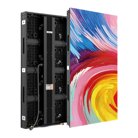
Chapter 1 Product Introduction 1.2 Cabinet Appearance 1.Positioning pin 2.Mounting hole 3.Power Supply and system box 4.Safety rope 5.Buckle 6.Power port 7.Signal port 8.Module Figure 1-1 Appearance of Front-maintenance Cabinet... -
Page 13: Specification
Chapter 1 Product Introduction 1.3 Specification Parameter Pixel composition 1R1G1B LED type Pixels per panel(dots) 128 x 64 104 x 52 84 x42 Physical Cabinet size 500x500x86 / 500x1000x86 Parameter (WxHxD)/(mm) Size ratio 1:1 / 1:2 Material Aluminum Weight(kg/panel) 9 / 16 Grey scale 14bits Refresh rate(Hz) -
Page 14: System Solution
Chapter 1 Product Introduction 1.4 System Solution The display system consists of the LED display, sending box, control PC, matrix, splicing controller and power distribution box (refer to the shipping list for details). The following shows a topology of the system for reference. Figure 1-2 System Topology... -
Page 15: Scope Of Application
Chapter 1 Product Introduction 1.5 Scope of Application The Uslim-O series products can be assembled seamlessly into a display screen of any size, and are extensively used for advertisements in sports stadiums, commercial buildings, banks, securities exchange, postal service stations, wharfs, shopping malls, bus stations, telecommunications, government offices, schools, restaurants, hotels, recreational centers, enterprises, and other outdoor places. -
Page 16: Chapter 2 Installation And Wiring
Chapter 2 Installation and Wiring Chapter 2 Installation and Wiring 2.1 Out-of-Box Inspection Check whether the packages are damaged. If the packages are intact, check the main components against the shipping list. If any inconsistency is found, contact us in time. e main components include cabinets, signal cable, power cable, USB cable, DVI cable, and sending box. - Page 17 Chapter 2 Installation and Wiring Figure 2-1 Rear View of Front-maintenance Cabinet Installation...
- Page 18 Chapter 2 Installation and Wiring Figure 2-3 4 Holes Connecting Plate Figure 2-2 Side View Figure 2-4 4 Holes Connecting Plate Figure 2-5 Screw of Connecting Plate...
-
Page 19: Front Maintenance Structures
Chapter 2 Installation and Wiring 2.2.2 Front Maintenance Structures The installation structure of the Uslim-O series can be designed based on the cabinet type. It is recommended that the thickness of the whole display be greater than or equal to 300 mm for the front maintenance structure, as shown in the following figure. -
Page 20: Wiring For Led Display
Chapter 2 Installation and Wiring 2.3 Wiring for LED Display 2.3.1 Common Cables Common cables used for the front-maintenance cabinet include: Signal Cable Passing Incoming Power Cable Incoming Signal Cable Through Cabinet USB Cable DVI Cable... -
Page 21: Signal Cable Connection
Chapter 2 Installation and Wiring 2.3.2 Signal Cable Connection Figure 2-8 shows the signal cable connection for cabinets with an arrangement of 5 cabinets (Width) × 2 cabinets (Height). Signal cables shall be connected based on the wiring diagram of the delivered products for the project. Figure 2-7 Signal Cable Connection Diagram... -
Page 22: Power Cable Connection
Chapter 2 Installation and Wiring 2.3.3 Power Cable Connection Figure 2-8 and figure 2-16 shows the power cable connection for cabinets with an arrangement of 5 cabinets (Width) × 2 cabinets (Height). Power cables shall be connected based on the wiring diagram of the delivered products for the project. AC Power Cable Figure 2-8 Power Cable Connection Diagram of Front-maintenance Cabinet... -
Page 23: Smart Control Distribution Box
Chapter 2 Installation and Wiring 2.3.4 Smart Control Distribution Box The Smart Control Distribution Box can be used for distributing electric power to the LED display, and has the function for real-time monitoring of the temperature, humidity, smoke, and mains voltage of the external environment. The control software has the scheduled start/stop function, allowing you to set any time for the LED display to be remotely started or stopped. - Page 24 Chapter 2 Installation and Wiring PLC connection of the smart control distribution box: The PLC communication system is RS485, It uses converter from control computer RS232 to RS485. For more detail information, please refer to our Intelligent Power Distribution Management System Manual. Figure 2-10 Distribution Box PLC Connection Diagram...
-
Page 25: Chapter 3 Led Display Control Setting
Chapter 3 LED Display Control Setting Chapter 3 LED Display Control Setting 3.1 Power-on Testing Before performing control setting on the LED display, confirm that each device is connected correctly. Before turning on the power of the LED display, you must use a multimeter to test the live wire, neutral wire, and ground wire of the AC power supply, in order to ensure they are not conductive with each other. -
Page 26: Preparation
Chapter 3 LED Display Control Setting 3.2 Preparation 3.2.1 Starting the Hardware Start the control PC Windows system. After the graphics card driver is activated, set graphics card of the control PC to replication mode and confirm that the green indicator of the sending box is blinking normally (blinking once per second). -
Page 27: Display Configuration
Chapter 3 LED Display Control Setting 3.3 Display Configuration Run UniLCT-Mars. Make sure that Control System on the main window is 1. Click the User option and select Advanced Login, as shown in Figure 3-3. Figure 3-3 Main Window of UniLCT-Mars Enter the initial password “admin”, as shown in Figure 3-4, to go to the advanced user window. - Page 28 Chapter 3 LED Display Control Setting Click Next, as shown in Figure 3-6: Figure 3-6 Screen Config The following window is displayed. Set Sending Board Resolution (1920×1080 recommended). Set Graphics Output Resolution to the same value as Sending Board Resolution. Then click Save to save the settings. Figure 3-7 Sending Board Configuration...
- Page 29 Chapter 3 LED Display Control Setting After configuring the parameters on the Sending Board page, click Scan Board to display the following window: Figure 3-8 Scan Board Configuration Click Load File to load the file xxxx.rcfg stored in the optical disk. Click Send To HW.
- Page 30 Chapter 3 LED Display Control Setting After configuring the parameters on the Scan Board page, click Screen Connection to display the following window: Click Read File to load the file xxxx.scr stored in the optical disk, as shown in Figure 3-9. Figure 3-9 Screen Connection 1...
-
Page 31: Brightness Adjustment
Chapter 3 LED Display Control Setting Click Send to HW. After sending, confirm that the screen is complete. Then click Save. Figure 3-10 Screen Connection with Loaded File 3.4 Brightness Adjustment On the main window, click Brightness, as shown in Figure 3-11, to display the brightness adjustment interface: Figure 3-11 Main Window for Advanced User... -
Page 32: Manual Adjustment
Chapter 3 LED Display Control Setting There are four brightness adjustment modes, namely Manual, Schedule, Auto, and Auto Adjustment by Hardware. After adjustment is finished, click Save to HW to save the adjustment results to the hardware. 3.4.1 Manual Adjustment Select Manual and adjust the brightness by dragging the scroll bar below Brightness Adjustment or directly modifying the brightness value (the maximum value is 255) next to the scroll bar. -
Page 33: Schedule Adjustment
Chapter 3 LED Display Control Setting 3.4.2 Schedule Adjustment Select Schedule and click Config to enter the Schedule interface, as shown below: Figure 3-13 Schedule Adjustment... - Page 34 Chapter 3 LED Display Control Setting As shown in Figure 3-14, you can set The retry number when adjustment failed to the required number of retries. Then click Add to enter the interface for adding scheduled adjustment information. Figure 3-14 Config Schedule File Set Start Time and Brightness.
-
Page 35: Auto Adjustment
Chapter 3 LED Display Control Setting After exiting, check whether the settings are correct. If you need to change the settings, select the information to be changed, click Edit, and change the information. Then click Confirm to finish the scheduled adjustment setting, as shown in Figure 3-16: Figure 3-16 Finishing the Scheduled Adjustment Setting 3.4.3 Auto Adjustment... - Page 36 Chapter 3 LED Display Control Setting After entering the function card management interface, click Add. Two options, namely Serial Port and Ethernet Port, are displayed. It is recommended you use Ethernet Port. See Figure 3-18: Figure 3-18 Function Card Management Interface Serial Port: You can add the function card directly connected to the computer serial port.
- Page 37 Chapter 3 LED Display Control Setting After adding the function card, click External Device, as shown in Figure 3-20: Figure 3-20 Finishing the Function Card Adding Process At the corresponding external device port, select the external device required and click Save, as shown in Figure 3-21: Figure 3-21 Configuring External Device...
- Page 38 Chapter 3 LED Display Control Setting Close this interface. On the main window, click Brightness to enter the display adjustment interface. Click Auto to enter the Auto Brightness window. Click the green "+" symbol on the top right corner of the window, as shown in Figure 3- 22:...
- Page 39 Chapter 3 LED Display Control Setting Figure 3-23 Ticking Off Light Sensor Based on the value read from the light sensor, set the values of Environment Brightness and Screen Brightness. Click OK to finish the auto adjustment setting process. See Figure 3-24: Figure 3-24 Finishing the Auto Adjustment Setting Process...
- Page 40 Chapter 3 LED Display Control Setting Set the start time at which auto brightness adjustment takes effect. On the Auto Brightness interface, click More Settings, as shown in Figure 3-25: Figure 3-25 Entering Advanced Configuration Interface...
- Page 41 Chapter 3 LED Display Control Setting The start time at which auto brightness adjustment takes effect is the value of Detect Period multiplying by the value of Read Times of Light Sensors. If, for example, the Detect Period is set to 60 seconds and the Read Times of Light Sensors is set to 5, the start time at which auto brightness adjustment is 5 minutes.
-
Page 42: Correction Coefficient Management
Chapter 3 LED Display Control Setting 3.5 Correction Coefficient Management Calibration of Uslim-O series product is set according to the actual project requirement. This section mainly introduces how to upload the Coefficients after changed modules and receiving card. On the main window, click Calibration, as shown in Figure 3-27, to display the screen... - Page 43 Chapter 3 LED Display Control Setting Configure Enable/Disable Calibration to Brightness, click Save, and then click Manage Coefficients to display the following window: Figure 3-28 Manage Coefficients Upload coefficients: Upload the correction coefficient database generated by the software or read back by the display screen to the screen. Save coefficients to database: Read back and save the coefficients from the screen to the coefficient database.
-
Page 44: Setting Coefficients For A New Receiving Card
Chapter 3 LED Display Control Setting 3.5.1 Setting Coefficients for a New Receiving Card 1) As shown in Figure 3-29, select Topology or List. Select the position of the replaced receiving card. Click Next: Figure 3-29 Selecting Area for New Receiving Card 2)... - Page 45 Chapter 3 LED Display Control Setting Select the corresponding correction coefficients: Figure 3-31 Selecting Correction Coefficients for Receiving Card Select Stable Upload and click Next: Figure 3-32 Uploading Correction Coefficients...
- Page 46 Chapter 3 LED Display Control Setting Adjust Coefficient: Perform a simple adjustment if the displaying effect is not good enough after you upload the coefficient. Then click Next. Figure 3-33 Simple Adjustment Red:Adjust the red brightness value of calibration coefficients. Green:Adjust the green brightness value of calibration coefficients.
-
Page 47: Setting Coefficients For A New Module
Chapter 3 LED Display Control Setting 3.5.2 Setting Coefficients for a New Module Select Position of the New Module: Select Topology or List. Then select the position of the receiving card where the new module is located. Double click the selected position: Figure 3-35 Selecting Cabinet for the New Module... - Page 48 Chapter 3 LED Display Control Setting Choose Display Mode to Modules. Select the position of the new module and click Next. Figure 3-36 Selecting Position of New Module Module Size:Set the size of the module in a cabinet. The software determines each module arrangement based on module size and cabinet size.
- Page 49 Chapter 3 LED Display Control Setting Save the correction coefficients to the hardware (Use similar steps in setting coefficients for a new receiving card. For details, refer to Step 4, Step 5, and Step 6 in Section 3.5.1) so that they are retentive after a power failure. Figure 3-37 Obtaining Correction Coefficients for a New Module...
-
Page 50: Pre-Storing Picture
Chapter 3 LED Display Control Setting 3.6 Pre-storing Picture On the Prestore Picture interface, you can save a picture as the prestored picture for the screen. This prestored picture can be set as a screen displayed upon booting, signal cable disconnection, or DVI signal absence. On the main window, click Tool and select Prestore Picture, as shown in Figure 3-38. - Page 51 Chapter 3 LED Display Control Setting 1) Prestore Picture Settings Select Picture: Click Browse to select the directory of the picture. Screen Effect: Set the selected picture to be displayed on the whole screen by means of stretching, tiling, or centering. Cabinet Effect: Set the selected picture to be displayed on each cabinet of the screen by means of stretching, tiling, or centering (the number of pictures displayed by each cabinet shall be equal to the number of receiving cards in the cabinet).
-
Page 52: Chapter 4 Led Display Playing Setting
Chapter 4 LED Display Playing Setting Chapter 4 LED Display Playing Setting 4.1 Selecting a Playing Solution The playing software UniStudio has three playing modes, namely Simple playing program, Professional playing program, and Priority programs of the page. Professional playing program is used most commonly. This Section introduces the Professional playing program only. -
Page 53: Playing Setting
Chapter 4 LED Display Playing Setting 4.2 Playing Setting 4.2.1 Display Window Setting Run the UniStudio, click Settings and select Display Setting, as in following fig: Figure 4-3 Display Window Setting Number of Display Windows: Indicates the number of display windows. To increase or decrease the number of display windows, re-enter the number of display windows in the box next to Number of Display Windows and then click Update. -
Page 54: Startup Setting
Chapter 4 LED Display Playing Setting 4.2.2 Startup Setting On the main window of the software, click Setting > Start Setting to enable the software to run automatically upon startup of the PC and to automatically activate a playing solution. See Figure 4-4: Figure 4-4 Startup Setting Auto Run after Power-on: If you enable this function, UniStudio will run automatically the next time when the PC is started. -
Page 55: Editing Professional Playing Solution
Chapter 4 LED Display Playing Setting Enable Auto Play: If you enable this function and specify a playing solution for the screen, the software will automatically activate the specified playing solution once the software is started. Instant plug and play of USB disk: If you enable this function, the PC will automatically read and activate the playing solution once the USB flash drive is inserted to the PC. - Page 56 Chapter 4 LED Display Playing Setting Editing the properties of the playing solution After adding a general time segment or interstitial segment, click General Segment 1 to edit the properties displayed in the segment editing area on the right side, as shown in Figure 4-6: Figure 4-6 Properties of General Time Segment...
-
Page 57: Editing The Program Page
Chapter 4 LED Display Playing Setting 4.3.2 Editing the Program Page Creating a program page As shown in Figure 4-7, right click General Segment or click the Add Program Page button in the toolbar to create a program page: Figure 4-7 Creating a Program Page... - Page 58 Chapter 4 LED Display Playing Setting Setting the properties After creating the program page, click Program 1 and set the background, displaying mode, and other properties displayed on the property page on the right side. See Figure 4-8: Figure 4-8 Properties of Program Page If you select Specify Number of Times, the next general program page is played after the preset Times to Play for the display window with the longest playing time on the current program page has been reached.
- Page 59 Chapter 4 LED Display Playing Setting When the current program page is played, the background picture or colour of the program page is displayed in the area not covered by the display window, as shown in Figure 4-9: Figure 4-9 Background of Program Page After adding the program page, you can move, copy, paste, or delete the program page by using the toolbar in the program page editing area, or by using the short-cut menu, as shown in Figure 4-10.
-
Page 60: Editing The Display Window
Chapter 4 LED Display Playing Setting 4.3.3 Editing the Display Window Adding a display window After adding a program page, you need to add a display window to this program page. Click Add Window on the toolbar of the program page to add a window to the current program page. - Page 61 Chapter 4 LED Display Playing Setting Setting the location and size of the display window The location and size of the new window is generated randomly and can be adjusted based on actual conditions by using either of the following two methods: Directly specify the new location and size in the setting pane, as shown in Figure 4-13: Figure 4-13 Setting the Window Size...
- Page 62 Chapter 4 LED Display Playing Setting Deleting a display window Select the window to be deleted. Click the delete key to delete the window, as shown in Figure 4-15: Figure 4-15 Deleting the Display Window Moving a display window Select the program or window. Click the direction key to adjust the playing sequence, as shown in Figure 4-16: Figure 4-16 Moving a Display Window...
-
Page 63: Editing The Media
Chapter 4 LED Display Playing Setting 4.3.4 Editing the Media Adding the media The type of window for adding the media is Common Window. Click the Add Media button of a common window to select media of different types to be added into the media list. - Page 64 Chapter 4 LED Display Playing Setting After adding the media, you can set the media texts and properties, as shown in Figure 4-18. Figure 4-18 Media Setting Window Setting the media properties Different media have different properties. After a medium in the media list is selected, the property page of this medium is displayed below the selected medium.
- Page 65 Chapter 4 LED Display Playing Setting Editing the media in the common window In an actual application, if different playing times are required for different media, you can select the media in the media list and then double click times to play to modify the playing times by either entering a new value or selecting a value from the drop-down list.
- Page 66 Chapter 4 LED Display Playing Setting Right click the media to perform operations on the selected media, as shown in Figure 4-21: Figure 4-21 Media Operation Menu Right click a blank area in the media playlist. A media playing menu is displayed, as shown in Figure 4-22: Figure 4-22 Media Playing Menu...
-
Page 67: Playing The Media
Chapter 4 LED Display Playing Setting 4.3.5 Playing the Media After the playing mode is edited or loaded, click the play key on the main toolbar to start the current playing mode, as shown in Figure 4-23: Figure 4-23 Play Key on the Toolbar After play is activated, the editing page is switched to the playing page, as shown in Figure 4-24: Figure 4-24 Play Information Page... - Page 68 Chapter 4 LED Display Playing Setting Clicking Pause or Stop on the toolbar can pause or stop the currently played program. You can also perform this operation by using the operation menu that appears when you right click the display window. See Figure 4-25: Figure 4-25 Short-cut Menu All display windows on the same program page plays simultaneously.
-
Page 69: Saving And Opening A Playing Solution
Chapter 4 LED Display Playing Setting 4.4 Saving and Opening a Playing Solution Save: After a playing solution is created, you can click Schedule on the toolbar and select Save or Save As to save the playing solution in the format of xxxx.plym. See Figure 4-27: Figure 4-27 Saving a Playing Solution File Open: After a playing solution is saved, you can directly click Schedule in the toolbar... -
Page 70: Chapter 5 Startup, Shutdown, And Maintenance
Chapter 5 Startup, Shutdown, and Maintenance Chapter 5 Startup, Shutdown, and Maintenance 5.1 Startup Sequence Start the distribution box for the LED display. Start the control computer. Start the video processor. Start the sending box. 5.2 Shutdown Sequence Shut down the video processor. Shut down the sending box. -
Page 71: Warm-Up Operation
Chapter 5 Startup, Shutdown, and Maintenance 5.4 Warm-up Operation If the LED display has been idle for a long period of time, perform warm-up operations before using the LED display. Set the prestored picture as follows when you initially start the LED display. This setting is for warm-up operation only. You do not need to set the prestored picture if the LED display is used frequently. -
Page 72: Ageing
Chapter 5 Startup, Shutdown, and Maintenance 5.4.2 Ageing On the main window, click Brightness to enter the brightness adjustment interface, as shown in Figure 5-2: Figure 5-2 Main Window for Advanced User Select Manual and set the brightness to 26 (the brightness is about 10%) by dragging the scroll bar below Brightness Adjustment. -
Page 73: Display Brightness And Ageing Time Table
Chapter 5 Startup, Shutdown, and Maintenance Return to the main window. Click Display Control to enter the Screen Control interface. Set Self Test to White. Click Send to finish the operation. As showed in Figure 5-4 and Figure 5-5. Figure 5-4 Display Control Fig 5-5 Display Control 5.4.3 Display Brightness and Ageing Time table Adjust the screen brightness and perform ageing based on the steps described in... -
Page 74: Chapter 6 Troubleshooting And Component Replacement
Chapter 6 Troubleshooting and Component Replacement Chapter 6 Troubleshooting and Component Replacement 6.1 Common Faults and Troubleshooting Methods 6.1.1 Failure in Lighting up the Display Causes: No power is supplied to the display or the control devices. The LED display does not have input signals. The control PC is in sleep mode or the graphics card is set incorrectly. -
Page 75: Screen Blinking
Chapter 6 Troubleshooting and Component Replacement 6.1.3 Screen Blinking Causes: The ports on the sending box are loose, or the signal cables are too long. The output resolution of the playing device or sending box is set incorrectly. Troubleshooting method: Check whether the DVI cable and signal cable are connected to the display and devices, or whether the length of signal cables exceeds the maximum transmission distance (the effective transmission distance shall not exceed 10 m for DVI cable,... -
Page 76: Failure In Lighting Up Part Of The Modules In The Cabinet
Chapter 6 Troubleshooting and Component Replacement 6.1.6 Failure in Lighting up Part of the Modules in the Cabinet Causes: Output of the power supply for the modules is faulty. Output of signal which controls the related modules is faulty. Troubleshooting method: Check DC voltage for the modules. - Page 77 Chapter 6 Troubleshooting and Component Replacement Replace the power supply and system card by following steps: Step Picture Instruction Operation After disconnecting the power supply of the screen body, refer to the method of maintaining and replacing the module before, remove the first and second row modules on the box body.
- Page 78 Chapter 6 Troubleshooting and Component Replacement Remove the fixing screw of the HUB card with a tool, then gently pull out the HUB card and replace it.
- Page 79 Chapter 6 Troubleshooting and Component Replacement Remove the HUB, and then use the tool to remove the fixed screw of the fixed receiving card to replace Take out the fixing screw of the power supply with the tool, and then gently take out the power supply and replace it.
- Page 80 Chapter 6 Troubleshooting and Component Replacement...
-
Page 81: Chapter 7 Packaging Transportation And Storage
Chapter 7 Packaging Transportation and Storage 7.1 Packaging The Uslim-O series products would be packaged in heavy duty case. The case would protected with pallets, box PE bag, cabinet corner protector, paper edge protector, packing iron buckle , cling film. -
Page 82: Chapter 8 After-Sales And Warranty
Unilumin provides warranty service to the products meet the requirements of this warranty term. Including quality problem, materials problem and manufacturing problem during normal use. Unilumin has the right to judge whether the product has defects and problems. 8.3.1 Warranty service type 1)Free Online Remote Service:... -
Page 83: Disclaimer
Unilumin to make a preliminary fault judgment. If the on-site analysis by Unilumin engineers determines that the quality problem is not covered by the warranty, the customer shall pay the travel expenses of the engineer and pay the technical service fee according to the after-sales service standard. -
Page 84: Warranty Service Process
16) Unilumin’s product don’t work or damage due to the match with equipment such as broadcasting and control system which are not provided by Unilumin, If the maintenance is required, the charging standard shall be implemented according to the contract. -
Page 85: Other
Unless confirmed by Unilumin in the form of the contract, attachments, etc., any warranty and content that conflicts with the terms of this warranty policy will automatically become invalid. The final interpretation of this warranty policy belongs to Shenzhen Unilumin Technology Co., Ltd. -
Page 86: Attachment 1 - Product Warranty Card
Attachment 2 - Path of Signal Cable inside the Cabinet Attachment 1 - Product Warranty Card Product Warranty Card Warranty Order No. Shipment Date Period Product Product Model Quantity Customer Contact Name Information Customer Address: Remark(s): Warranty Record Completion Signature of Warranty Date Fault and Troubleshooting Date... -
Page 87: Contact Information
Daya Bay manufacturing center: Longsheng Fifth Road, western Daya Bay, Huiyang District, Huizhou, China. Telephone (switchboard): +86-755-29918999 Fax: +86-755-29912092 Website: www.unilumin.com Service Department Tel: + 86- (0) 755-29592226 (direct line) 24-hour service hotline: 400-677-3888 Display sales department International department (direct line): + 86- (0) 755-29918999... - Page 88 E-mail: Customer-service@unilumin.com Hotline: 400-677-3888 Unilumin USA Subsidiary Name: UNILUMIN USA LLC. Unilumin USA HQ Address: 254W 31st St. 12th Floor, New York, NY 10001 Email: service@unilumin-usa.com Tel: 001 844-263-3675 EUROPEAN SERVICE CENTER Address: Parellaan 28, 2132 WS, hoofddorp, the Netherlands E-mail: euro-support@unilumin.com...
- Page 89 UNILUMIN GERMANY GMBH Address: Raiffeisenstr. 30 - 70794 Filderstadt E-mail: info@unilumin.de Tel: +49 711 38967 898 UNILUMIN AUSTRALIA PTY LTD (BUSINESS IN OCEANIA) Address: Level 1, Trak Centre, 443/449 Toorak Road, Toorak, VIC 3142 Tel: +61 3 9006 8960 +86-755-29918999...
- Page 90 Contact Information...
Need help?
Do you have a question about the Uslim-O Series and is the answer not in the manual?
Questions and answers