Table of Contents
Advertisement
Quick Links
Advertisement
Table of Contents

Related Manuals for Danfoss BOCK UL-HGX66e


Summary of Contents for Danfoss BOCK UL-HGX66e
- Page 1 Reciprocating Compressor ® BOCK UL-HGX66e Operating guide UL-HGX66e/1340 ML 31 UL-HGX66e/1340 S 37 UL-HGX66e/1540 ML 36 UL-HGX66e/1540 S 42 UL-HGX66e/1750 ML 44 UL-HGX66e/1750 S 50 UL-HGX66e/2070 ML 50 UL-HGX66e/2070 S 60 Translation of the original instructions AQ450438640296en-US0301...
-
Page 2: Table Of Contents
Short description ....................... 6 Name plate (example) ......................7 Type key (example) ......................7 Areas of application ......................8 Refrigerants ........................8 Oil charge .......................... 8 Limits of application ......................8 2 | AQ450438640296en-US0301 © Danfoss | Climate Solutions | 2024.04... - Page 3 Capacity regulator ......................28 Oil separator ........................29 Oil level regulator ......................30 Technical data........................ 31 Dimensions and connections ..................32 Declaration of incorporation ..................34 UL-Certificate of Compliance..................36 AQ450438640296en-US0301 | 3 © Danfoss | Climate Solutions | 2024.04...
-
Page 4: Safety
140°F (60°C) on the discharge side or below 32°F (0°C) on the suction side can be reached. - Contact with refrigerant must be avoided. Contact with refrigerant can cause severe burns and skin damage. 4 | AQ450438640296en-US0301 © Danfoss | Climate Solutions | 2024.04... -
Page 5: Intended Use
As well as professions with comparable training that enables personnel to assemble, install, maintain and repair refrigeration and air-conditioning systems. Personnel must be capable of assessing the work to be carried out and recognizing any potential dangers. AQ450438640296en-US0301 | 5 © Danfoss | Climate Solutions | 2024.04... -
Page 6: Product Description
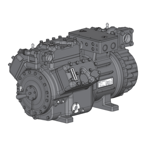
Discharge shut-off valve Cylinder Valve plate cover Name plate Motor section Oil pump Drive section Oil sight glass Fig. 1 Dimension and connection values can be found in chapter 10. 6 | AQ450438640296en-US0301 © Danfoss | Climate Solutions | 2024.04... -
Page 7: Name Plate (Example)
Identification UL compressor HG - Hermetic Gas-Cooled (suction gas-cooled) ¹ X - Ester oil charge ² S - More powerful motor ML - Motor for normal cooling and deep freezing AQ450438640296en-US0301 | 7 © Danfoss | Climate Solutions | 2024.04... -
Page 8: Areas Of Application
When operating in the vacuum range, there is a danger of air entering on the suction side. This can cause chemical reactions, a pressure rise in the condenser and an elevated compressed-gas temperature. Prevent the ingress of air at all costs! 8 | AQ450438640296en-US0301 © Danfoss | Climate Solutions | 2024.04... -
Page 9: Compressor Assembly
Setup on an even surface or frame with sufficient load- bearing capacity. Single compressor preferably on vibration damper. Duplex and parallel circuits always rigid. Installation of pipe vibration mufflers is recommended! AQ450438640296en-US0301 | 9 © Danfoss | Climate Solutions | 2024.04... -
Page 10: Pipe Connections
As soon as the motor and the compressor reach their rated speed, the solenoid valve closes and the non-return valve opens (Fig. 6). The compressor now works under normal load. Solenoid valve actuated Non-return valve closed Fig. 5 10 | AQ450438640296en-US0301 © Danfoss | Climate Solutions | 2024.04... -
Page 11: Laying Suction And Pressure Lines
A rule of thumb: Always lay the first pipe section starting from the shut-off valve downwards and parallel to the drive shaft. Rigid As short as fixed point Fig. 7 possible AQ450438640296en-US0301 | 11 © Danfoss | Climate Solutions | 2024.04... -
Page 12: Operating The Shut-Off Valves
—> Service connection opened / shut-off valve opened. After activating the spindle, generally fit the spindle protection cap again and tighten with 14-16 Nm (10-12 lb-ft). This serves as a second sealing feature during operation. 12 | AQ450438640296en-US0301 © Danfoss | Climate Solutions | 2024.04... -
Page 13: Suction Pipe Filter And Filter Drier
For motor protection use a current-dependent and time-delayed overload protection device for moni- toring all three phases. Set the overload protection device so that it must be actuated within 2 hours, if there is 1.2 times the max. working current. AQ450438640296en-US0301 | 13 © Danfoss | Climate Solutions | 2024.04... -
Page 14: Standard Motor, Design For Direct Or Partial Winding Start
This winding division reduces the start-up current needed for a part winding start to approx. 50% of that for a direct start. A mechanical unloaded start with bypass solenoid valve is not required. 14 | AQ450438640296en-US0301 © Danfoss | Climate Solutions | 2024.04... - Page 15 After the motor starts up via partial winding 1, partial winding 2 must be switched on after a maximum delay of one second. Failure to comply can adversely affect the service life of the motor. AQ450438640296en-US0301 | 15 © Danfoss | Climate Solutions | 2024.04...
-
Page 16: Basic Circuit Diagram For Part Winding Start With Standard Motor
Release switch (thermostat) Bearb. bauknecht DELTA-P II Oil differential pressure sensor DELTA-P II (accessory) Gepr. 03.11.2020 Οnderung Datum Name Norm Urspr. Ers. f. Ers. d. Oil sump heater Compressor motor 16 | AQ450438640296en-US0301 © Danfoss | Climate Solutions | 2024.04... - Page 17 Electronic trigger unit INT69 G Delay relay for contactor switchover Main switch PW INT69 HG44/66 Mains contactor (part winding 1) Mains contactor (part winding 2) BOCK COMPRESSORS Control voltage switch AQ450438640296en-US0301 | 17 © Danfoss | Climate Solutions | 2024.04...
-
Page 18: Special Motor: Design For Direct Or Star-Delta Start
Special motor: design for direct or star-delta start A mechanical unloaded start with bypass solenoid valve is required for the star-delta start. Designation on the name plate ∆ / Y 18 | AQ450438640296en-US0301 © Danfoss | Climate Solutions | 2024.04... - Page 19 Star-delta start Direct start only In the factory the motor is wired for direct starting at high voltage. The brides are to be removed for star delta starting at low voltage. AQ450438640296en-US0301 | 19 © Danfoss | Climate Solutions | 2024.04...
-
Page 20: Basic Circuit Diagram For Star-Delta Start 230 V ∆ / 400 V Y
Release switch (thermostat) Datum 20.02.2009 Bearb. bauknecht DELTA PII Oil differential pressure sensor DELTA-P II (accessory) Gepr. 03.11.2020 Oil sump heater Οnderung Datum Name Norm Urspr. Ers. f. Ers. d. Compressor motor 20 | AQ450438640296en-US0301 © Danfoss | Climate Solutions | 2024.04... - Page 21 Control power circuit fuse INT69 G Electronic trigger unit INT69 G Delay relay for contactor switchover Main switch Mains contactor D/S INT69 HG44/66 neu Δ-contactor BOCK COMPRESSORS Y-contactor Control voltage switch AQ450438640296en-US0301 | 21 © Danfoss | Climate Solutions | 2024.04...
-
Page 22: Electronic Trigger Unit Int69 G
This would destroy N 43 43 11 X2 1 the trigger unit INT69 G and PTC Θ Θ Θ sensors. Steuerstrom- Steuerstrom- Control circuit kreis kreis Θ Fig. 14 Terminal box 22 | AQ450438640296en-US0301 © Danfoss | Climate Solutions | 2024.04... -
Page 23: Function Test Of The Trigger Unit Int69 G
El. data: 115 V AC 60 Hz, 160 W. Connection to the current path of the safety control chain is not permitted. AQ450438640296en-US0301 | 23 © Danfoss | Climate Solutions | 2024.04... -
Page 24: Capacity Regulator (Accessories)
Rotational speed 0 - f-min f-min - f-max range ca. 4 s Start-up time < 1 s immediately Switch-off time f-min/f-max see chapter 9: Technical data: permissible frequency range 24 | AQ450438640296en-US0301 © Danfoss | Climate Solutions | 2024.04... -
Page 25: Commissioning
At the end of the evacuation process, the vacuum should be < 1.5 mbara (0.02 psia) when the pump is switched off. Repeat this process as often as is required. AQ450438640296en-US0301 | 25 © Danfoss | Climate Solutions | 2024.04... -
Page 26: Refrigerant Charge
Particularly in critical systems (e.g. several evaporator points), measures are recommended such as replacement of liquid traps, solenoid valve in the liquid line, etc. There should be no movement of coolant whatsoever while the compressor is at a standstill. 26 | AQ450438640296en-US0301 © Danfoss | Climate Solutions | 2024.04... -
Page 27: Maintenance
When the compressor is depressurised, undo the fastening screws of the shut-off valves. Remove the compressor using an appropriate hoist. Dispose of the oil inside in accordance with the applicable national regulations. AQ450438640296en-US0301 | 27 © Danfoss | Climate Solutions | 2024.04... -
Page 28: Accessories
15 Nm. Magnetic coil Wet thread sides with ester oil. Insert magnetic coil, fasten it with knurled Control unit nut and connect it. (pilot valve) Seal ring Fig. 21 28 | AQ450438640296en-US0301 © Danfoss | Climate Solutions | 2024.04... -
Page 29: Oil Separator
The oil return from the oil separator must be guided back at the intended connection (D1) on the compressor housing. A direct oil return into the suction line from the oil separator is not permissible. Ensure that the oil separator is properly dimensioned. AQ450438640296en-US0301 | 29 © Danfoss | Climate Solutions | 2024.04... -
Page 30: Oil Level Regulator
Mechanical oil level regulator 3 hole connection diagram for 3-Loch-Anschlussbild für ESK, ESK, AC&R and CARLY AC&R und CARLY at the "O" connection 3 hole diagram for TraxOil 3-Loch-Anschlussbild für TraxOil 30 | AQ450438640296en-US0301 © Danfoss | Climate Solutions | 2024.04... -
Page 31: Technical Data
380-420 V Y/YY - 3 - 50 Hz PW 440-480 V Y/YY - 3 - 60 Hz PW Voltage PW = Part Winding, Winding ratio : 50%/50% Displacement (1450 rpm / 1740 rpm) No. of cylinders Type UL-HGX66e/ AQ450438640296en-US0301 | 31 © Danfoss | Climate Solutions | 2024.04... -
Page 32: Dimensions And Connections
Zust. / Rev. Änd.-Nr. / Mod-No. Datum / Date Bearb. / Edited Geprüft / Appr. Maß / Dimension Passung / Clearance of the grant of a patent, utility model or design. 32 | AQ450438640296en-US0301 © Danfoss | Climate Solutions | 2024.04... - Page 33 Connection oil pressure differential sensor M20x1.5 Connection oil service valve 1 / 4 ÖV “ NPTF Connection oil temperature sensor 1 / 8 “ NPTF Connection for refrigerant injection “ NPTF AQ450438640296en-US0301 | 33 © Danfoss | Climate Solutions | 2024.04...
-
Page 34: Declaration Of Incorporation
Bock GmbH Authorized person for compiling and handing Alexander Layh over technical documentation: Benzstraße 7 72636 Frickenhausen, Germany Frickenhausen, 04th of January 2021 i. A. Alexander Layh, Global Head of R&D 34 | AQ450438640296en-US0301 © Danfoss | Climate Solutions | 2024.04... - Page 35 Authorized representative for compiling and handing Danfoss LTD., 22 Wycombe End, over technical documentation: HP9 1NB, GB Frickenhausen, 19th of January 2024 i. A. Alexander Layh, Global Head of R&D AQ450438640296en-US0301 | 35 © Danfoss | Climate Solutions | 2024.04...
-
Page 36: Ul-Certificate Of Compliance
12| UL-Certificate of Compliance Dear customer, the Certificate of Compliance can be downloaded by the following QR-Code: https://vap.bock.de/stationaryapplication/Data/ DocumentationFiles/UL-Certificateofconformity.pdf 36 | AQ450438640296en-US0301 © Danfoss | Climate Solutions | 2024.04... - Page 37 AQ450438640296en-US0301 | 37 © Danfoss | Climate Solutions | 2024.04...
- Page 38 38 | AQ450438640296en-US0301 © Danfoss | Climate Solutions | 2024.04...
Need help?
Do you have a question about the BOCK UL-HGX66e and is the answer not in the manual?
Questions and answers