Advertisement
Quick Links
Reciprocating Compressor
UL- HGX 34 CO
BOCK
®
Operating guide
UL-HGX34/110 ML(P) 11 CO
UL-HGX34/130 ML(P) 14 CO
UL-HGX34/150 ML(P) 16 CO
UL-HGX34/170 ML(P) 19 CO
UL-HGX34/190 ML(P) 22 CO
UL-HGX34/210 ML(P) 24 CO
UL-HGX34/230 ML(P) 26 CO
UL-HGX34/290 ML(P) 34 CO
Translation of the original instructions
T
UL-HGX34/110 S(P) 16 CO
2
T
UL-HGX34/130 S(P) 19 CO
2
T
UL-HGX34/150 S(P) 22 CO
2
T
UL-HGX34/170 S(P) 28 CO
2
T
UL-HGX34/190 S(P) 30 CO
2
T
UL-HGX34/210 S(P) 31 CO
2
T UL-HGX34/230 S(P) 35 CO
2
T UL-HGX34/290 S(P) 48 CO
2
T
2
T
UL-HGX34/110 SH(P) 16 CO
2
T
UL-HGX34/130 SH(P) 19 CO
2
T UL-HGX34/150 SH(P) 22 CO
2
T UL-HGX34/170 SH(P) 28 CO
2
T UL-HGX34/190 SH(P) 30 CO
2
T
UL-HGX34/210 SH(P) 31 CO
2
T UL-HGX34/230 SH(P) 35 CO
2
T UL-HGX34/290 SH(P) 48 CO
2
AQ450435171288en-US0201
T
2
T
2
T
2
T
2
T
2
T
2
T
2
T
2
Advertisement

Related Manuals for Danfoss BOCK UL-HGX34 CO2 T


Summary of Contents for Danfoss BOCK UL-HGX34 CO2 T
- Page 1 Reciprocating Compressor UL- HGX 34 CO BOCK ® Operating guide UL-HGX34/110 ML(P) 11 CO UL-HGX34/110 S(P) 16 CO UL-HGX34/110 SH(P) 16 CO UL-HGX34/130 ML(P) 14 CO UL-HGX34/130 S(P) 19 CO UL-HGX34/130 SH(P) 19 CO UL-HGX34/150 ML(P) 16 CO UL-HGX34/150 S(P) 22 CO T UL-HGX34/150 SH(P) 22 CO UL-HGX34/170 ML(P) 19 CO UL-HGX34/170 S(P) 28 CO...
- Page 2 1.4 Qualifications required of personnel..................5 Product description......................6 2.1 Short description........................6 2.2 Name plate..........................7 2.3 Type key..........................7 2.4 Type key compressors with LSPM Motor (Line Start Permanent Magnet)......8 2 | AQ450435171288en-US0201 © Danfoss | Climate Solutions | 2023.07...
- Page 3 7.3 Spare parts recommendation / accessories................29 7.4 Lubricants / oil........................29 7.5 Decommissioning........................29 Technical data........................ 30 Dimensions and connections..................34 Declaration of incorporation..................36 UL-Certificate of Compliance..................38 AQ450435171288en-US0201 | 3 © Danfoss | Climate Solutions | 2023.07...
- Page 4 140°F (60°C) on the pressure side or below 32°F (0°C) on the suction side can be reached. • Avoid contact with refrigerant under any circumstances. Contact with refrigerant can lead to severe burns and skin irritations. 4 | AQ450435171288en-US0201 © Danfoss | Climate Solutions | 2023.07...
- Page 5 • As well as professions with comparable training, which enable personnel to assemble, install, maintain and repair refrigeration and air-conditioning systems. • Personnel must be capable of assessing the work to be carried out and recognizing any potential dangers. AQ450435171288en-US0201 | 5 © Danfoss | Climate Solutions | 2023.07...
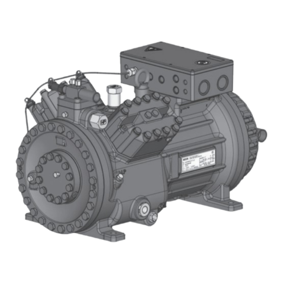
- Page 6 Name plate Oil pump Oil sight glass Fig. 1 Discharge shut-off valve Terminal box Cylinder cover Suction shut-off valve Fig. 2 Dimension and connection values can be found in chapter 9 6 | AQ450435171288en-US0201 © Danfoss | Climate Solutions | 2023.07...
- Page 7 ML - Normal cooling and deep freezing at low and medium evaporation temperatures ³ - For frequency regulation and extended limits of application SH - For high evaporating temperatures eg. heat pumps, different oil charge AQ450435171288en-US0201 | 7 © Danfoss | Climate Solutions | 2023.07...
- Page 8 The oil level must be in the Max. visible part of the sight glass; damage to the compressor Oil level 32 fl.oz/ is possible if overfilled or 0.9 Ltr. Min. underfilled! Fig. 4 8 | AQ450435171288en-US0201 © Danfoss | Climate Solutions | 2023.07...
- Page 9 10 % - 95 %, no condensation. Do not store in a corrosive, dusty, vaporous atmosphere or in a com- bustible environment. Use transport eyelet. Do not lift manually! Use lifting gear! AQ450435171288en-US0201 | 9 © Danfoss | Climate Solutions | 2023.07...
- Page 10 On its high-pressure side, the compressor has a shut-off valve with multi-sided cutting ring for safe • installation of the discharge line. Cutting ring function after tightening the union nut Collar Fig. 6 Figure similar 10 | AQ450435171288en-US0201 © Danfoss | Climate Solutions | 2023.07...
- Page 11 4.6 Flange shut-off valves (HP/LP) Risk of injury. The compressor must be depressurized through connections A and B before commencing any work and prior to connecting to the refrigerant system. Fig. 7 Fig. 8 AQ450435171288en-US0201 | 11 © Danfoss | Climate Solutions | 2023.07...
- Page 12 Before opening or closing the shut-off valve, release the valve spindle seal by approx. of a turn counter-clockwise. After activating the shut-off valve, re-tighten the adjustable valve spindle seal clockwise. Tighten Release Valve spindle seal Fig. 10 Fig. 11 12 | AQ450435171288en-US0201 © Danfoss | Climate Solutions | 2023.07...
- Page 13 For systems with long pipes and higher degree of contamination, a filter on the suction-side is recommended. The filter has to be renewed depending on the degree of contamination (reduced pressure loss). AQ450435171288en-US0201 | 13 © Danfoss | Climate Solutions | 2023.07...
- Page 14 Adjust the overload protection device so that it must be actuated within 2 hours at 1.2 times the maximum working current. For compressors with LSPM motor, a faster responding overload protection device is recommended. 14 | AQ450435171288en-US0201 © Danfoss | Climate Solutions | 2023.07...
- Page 15 (1U1 / 1V1 / 1W1) and via QA3 to winding 2 (50 %) (2U1 / 2V1 / 2W1). The motor contactors (QA2 / QA3) are each to be rated for approx. 50 % of the max. operating current. AQ450435171288en-US0201 | 15 © Danfoss | Climate Solutions | 2023.07...
- Page 16 DELTA-P II Oil differential pressure sensor DELTA-P II (accessory) Gepr. 26.11.2020 Οnderung Datum Name Norm Urspr. Ers. f. Ers. d. Oil sump heater Compressor motor * With several connect them in series 16 | AQ450435171288en-US0201 © Danfoss | Climate Solutions | 2023.07...
- Page 17 Electronic trigger unit INT69 G Delay relay for contactor switch over PW INT69 HG44/66 Main switch BOCK COMPRESSORS Mains contactor (part winding 1) Mains contactor (part winding 2) Control voltage switch AQ450435171288en-US0201 | 17 © Danfoss | Climate Solutions | 2023.07...
- Page 18 5 | Electrical connection 5.4 Special motor: design for direct or star-delta start Designation on the name plate ∆ / Y 18 | AQ450435171288en-US0201 © Danfoss | Climate Solutions | 2023.07...
- Page 19 Star-delta start-up is only possible for 280 V power supply. Example: 280 V Δ 460 V Y Direct start Star-delta start Direct start only (not on LSPM Motor) Only direct start is possible with LSPM Motor. AQ450435171288en-US0201 | 19 © Danfoss | Climate Solutions | 2023.07...
- Page 20 DELTA PII Oil differential pressure sensor DELTA-P II (accessory) Gepr. 03.11.2020 Οnderung Datum Name Norm Urspr. Ers. f. Ers. d. Oil sump heater Compressor motor * With several connect them in series 20 | AQ450435171288en-US0201 © Danfoss | Climate Solutions | 2023.07...
- Page 21 Control power circuit fuse INT69 G Electronic trigger unit INT69 G Delay relay for contactor switch over D/S INT69 HG44/66 neu Main switch BOCK COMPRESSORS Mains contactor Δ-contactor Y-contactor Control voltage switch AQ450435171288en-US0201 | 21 © Danfoss | Climate Solutions | 2023.07...
- Page 22 5.8 Function test of the trigger unit INT69 G Before commissioning, after troubleshooting or making changes to the control power circuit, check the functionality of the trigger unit. Perform this check using a continuity tester or gauge. 22 | AQ450435171288en-US0201 © Danfoss | Climate Solutions | 2023.07...
- Page 23 For start-up and low speed operation, a voltage boost of 10-20V is recommended to slightly reduce the motor current and compensate for voltage drops through the compressor supply line (and filtering devices, if present). AQ450435171288en-US0201 | 23 © Danfoss | Climate Solutions | 2023.07...
- Page 24 Only dry test gases may be used for the leak test, e.g. nitrogen N2 min. 4.6 (= purity 99.996 % or higher). 24 | AQ450435171288en-US0201 © Danfoss | Climate Solutions | 2023.07...
- Page 25 Avoid overfilling the machine with refrigerant! Do not charge liquid refrigerant into the suction-side on the compressor. Do not mix additives with the oil and refrigerant. AQ450435171288en-US0201 | 25 © Danfoss | Climate Solutions | 2023.07...
- Page 26 The pressure reduction for the pressure switches can occur either at the suction and pressure lines between the shut-off valve and compressor or at the non-lockable connections for the shut-off valves (connections A and B, see Chapter 9). 26 | AQ450435171288en-US0201 © Danfoss | Climate Solutions | 2023.07...
- Page 27 EN 378-2 or appropriate safety standards. Failure to observe can result in risk of injury from CO streaming out of the two pressure relief valves! streaming Fig. 18 AQ450435171288en-US0201 | 27 © Danfoss | Climate Solutions | 2023.07...
- Page 28 CO is produced which blocks the outlet and could hinder the streaming out of CO . Otherwise, there is the danger that pressure can be built up again. 28 | AQ450435171288en-US0201 © Danfoss | Climate Solutions | 2023.07...
- Page 29 For this reason the suction side (LP) and the high pressure side (HP) of the compressor have to be secured by decompression valves. AQ450435171288en-US0201 | 29 © Danfoss | Climate Solutions | 2023.07...
- Page 30 440-480 V Y/YY - 3 - 60 Hz PW Voltage PW = Part Winding Winding ratio : 50% / 50% Displacement (1450 / 1740 rpm) No. of cylinders Type UL-HGX34/ 30 | AQ450435171288en-US0201 © Danfoss | Climate Solutions | 2023.07...
- Page 31 20 - 70 380-420 V Y/YY - 3 - 50 Hz PW 440-480 V Y/YY - 3 - 60 Hz PW PW = Part Winding Winding ratio : 50% / 50% AQ450435171288en-US0201 | 31 © Danfoss | Climate Solutions | 2023.07...
- Page 32 220-240 V ∆ / 380-420 V Y - 3 - 50 Hz Voltage 265-290 V ∆ / 440-480 V Y - 3 - 60 Hz Displacement (1500 / 1800 rpm) No. of cylinders Type UL-HGX34/ 32 | AQ450435171288en-US0201 © Danfoss | Climate Solutions | 2023.07...
- Page 33 8 | Technical data 20 - 70 220-240 V ∆ / 380-420 V Y - 3 - 50 Hz 265-290 V ∆ / 440-480 V Y - 3 - 60 Hz AQ450435171288en-US0201 | 33 © Danfoss | Climate Solutions | 2023.07...
- Page 34 0h | Zubehör DCR22 & Heißgastemperatursensor aufgenommen 09.05.22 S. Büttner packaging for safe transportation). 34 | AQ450435171288en-US0201 © Danfoss | Climate Solutions | 2023.07 Weitergabe sowie Vervielfältigung dieses Dokuments, 0h | BS-Befestigungsteile aus Lieferumfang entfernt und als Zubehör ergänzt 11614 A. Layh 06.05.22...
- Page 35 Decompression valve HP M24x1,5 Decompression valve LP M22x1,5 7 / 16 “ UNF Connection for Schrader valve, suction side 7 / 16 “ UNF Connection for Schrader valve, discharge side AQ450435171288en-US0201 | 35 © Danfoss | Climate Solutions | 2023.07...
- Page 36 Bock GmbH Authorized person for compiling and handing Alexander Layh over technical documentation: Benzstraße 7 72636 Frickenhausen, Germany Frickenhausen, 04th of January 2021 i. A. Alexander Layh, Global Head of R&D 36 | AQ450435171288en-US0201 © Danfoss | Climate Solutions | 2023.07...
- Page 37 Bock GmbH Authorized person for compiling and handing Alexander Layh over technical documentation: Benzstraße 7 72636 Frickenhausen, Germany Frickenhausen, 14th of October 2022 i. A. Alexander Layh, Global Head of R&D AQ450435171288en-US0201 | 37 © Danfoss | Climate Solutions | 2023.07...
- Page 38 11 | UL-Certificate of Compliance Dear customer, the Certificate of Compliance can be downloaded by the following QR-Code: https://vap.bock.de/stationaryapplication/Data/ DocumentationFiles/COC CO2 trans.pdf 38 | AQ450435171288en-US0201 © Danfoss | Climate Solutions | 2023.07...
- Page 39 AQ450435171288en-US0201 | 39 © Danfoss | Climate Solutions | 2023.07...
- Page 40 40 | AQ450435171288en-US0201 © Danfoss | Climate Solutions | 2023.07...
Need help?
Do you have a question about the BOCK UL-HGX34 CO2 T and is the answer not in the manual?
Questions and answers