
Related Manuals for DX Engineering SkyLark 2X7


Summary of Contents for DX Engineering SkyLark 2X7
- Page 1 SkyLark 2X7 12 & 17 Meter Dual-Band Yagi Antenna DXE-2X7-INS Rev 2 © DX Engineering 2024 1200 Southeast Ave. - Tallmadge, OH 44278 USA Phone: (800) 777-0703 ∙ Tech Support and International: (330) 572-3200 E-mail: DXEngineering@DXEngineering.com...
-
Page 2: Required Tools And Items
DX Engineering SkyLark 2X7 Congratulations on the purchase of your DX Engineering SkyLark 2X7. You now possess the finest computer optimized dual-band on the market. The SkyLark features low weight, zero mast torque, a balanced beam and high wind survival. Corrosion and UV resistant materials are used throughout its construction. -
Page 3: Before You Start
Before You Start WARNING: INSTALLATION OF THIS PRODUCT NEAR POWER LINES IS DANGEROUS. FOR YOUR SAFETY FOLLOW THE INSTALLATION INSTRUCTIONS. WARNING: AT NO TIME DURING ASSEMBLY, INSTALLATION, ADJUSTMENT, OR OPERATION SHOULD ANY PART OF THIS PRODUCT BE ALLOWED TO COME INTO CONTACT WITH ELECTRIC POWER LINES, NOR SHOULD THIS PRODUCT BE INSTALLED IN SUCH A WAY THAT ANY PART OF IT MAY CONTACT POWER LINES DURING NORMAL OPERATION OR IN THE EVENT OF STRUCTURAL FAILURE. - Page 4 Pop Rivet Installation The elements of your SkyLark 2X7 are assembled with blind rivets. What is the difference between a blind rivet and a rivet? The short answer is there is no difference between Pop® rivets, pop rivets, or blind rivets.
-
Page 5: Choosing An Installation Site
SkyLark 2X7. Select a place clear of power lines or other obstructions. When completed, the SkyLark 2X7 should be mounted at least 30 feet (9.1 meters) above the ground for proper operation. The SkyLark 2X7 should be able to rotate without hitting anything. - Page 6 Part Lists SKYLARK 17 METER ELEMENTS - PARTS LIST Description Size Inch (cm) 17M REFLECTOR ELEMENT SPLICE 17M 5/8” (1.5875) X 47-7/8” (121.6025) SECTION A 17M 3/4” (1.905) X 47-7/8” (1,216) SECTION B 17M 5/8” (1.5875) X 47-7/8” (121.6025) SECTION C 17M 1/2”...
- Page 7 SKYLARK DRIVEN ELEMENT HARDWARE KIT - PARTS LIST Description SADDLE 1” (2.54cm) 17 METER DRIVEN ELEMENT ELEMENT SPACER ASSEMBLIES with Mounting Screws and Hex Nuts COIL - 12/17 METER SKYLARK with Ring Terminals Soldered ELEMENT HARDWARE PACKAGE - PARTS LIST Description # 8 SPLIT RING LW 18-8 # 8-32 HEX NUT 18-8 (11/32 X 1/8)
- Page 8 BOOM HARDWARE PACKAGE - PARTS LIST Description 1/4-20 HEX NUT 18-8 1/4 SPLIT RING WASHER 18-8 1/4-20 X 0.625 PHILLIPS HEAD BOLT 18-8 1/4-20 X 2.750 PHILLIPS HEAD BOLT 18-8 PROTECTIVE BOOM END CAP, 2” (5.08cm) BOOM/MAST PLATES - PARTS LIST Description 1/4-20 HEX NUT 18-8 (7/16 X 7/32) 1/4 SPLIT RING WASHER 18-8...
- Page 9 BALUN, MOUNTING BRACKET AND HARDWARE PARTS LIST DX Engineering 1:1 BALUN W/ WEEP HOLES BALUN CONNECTION STRAPS, ALUMINUM with mounting hardware and 2 Nyloc Hex Nuts BALUN MOUNTING BRACKET BALUN MOUNTING BRACKET FLAT WASHERS BALUN MOUNTING BRACKET NYLOC HEX NUTS...
-
Page 10: Boom Assembly
Boom Assembly Each boom section labeled for easy assembly. In the event that the letters have worn off, each section may be identified using the boom dimensions. Boom Description Size Inch (cm) BOOM SECTION A 2” (5.08) X 47-7/8” (121.6025) BOOM SECTION B 2”... - Page 11 Element Platform Mounts There are seven aluminum element platforms. These are mounted at the seven element stations. There are already a temporary bolts and hardware through the boom (installed finger tight during boom assembly) where the element platforms will mount. When mounting these platforms it is necessary to remove the bolts and hardware as you install the element platform mounts.
- Page 12 Boom to Mast Mounting Clamp Install the Boom to Mast mounting clamp on the Boom in the position as shown. Use the appropriate bolt, split washer, hex nut hardware to hold the clamp in place as shown. Note that the mast clamp can be mounted in either side of the boom depending on where the user wants it.
- Page 13 Element Assemblies NOTE: Each band has the tubes in a separate bag with a tag indicating which element the tubes belong with. When opening the bag, just open one end. As tubes are needed, remove them from their bag to avoid mixing up element tubes. The part number label on the bag will help to keep element tubes separated and identified prior to use.
- Page 14 17 Meter Reflector Element construction and mount to boom 17 Meter Reflector Description Size Inch (cm) ELEMENT SPLICE 17M 5/8” (1.5875) X 47-7/8” (121.6025) □ □ ELEMENT SECTION A 17M 3/4” (1.905) X 47-7/8” (1,216) □ ELEMENT SECTION B 17M 5/8”...
- Page 15 12 Meter Reflector Element construction and mount to boom 12 Meter Reflector Description Size Inch (cm) ELEMENT SECTION A 12M 3/4” (1.905) X 35-7/8” (91.1225) □ □ ELEMENT SECTION B 12M 5/8” (1.5875) X 35-7/8” (91.1225) □ ELEMENT SECTION C 12M 1/2”...
- Page 16 17 Meter Driven Element construction and mount to boom 17 Meter Driven Description Size Inch (cm) ELEMENT SECTION A 17M 3/4” (1.905) X 47-7/8” (1,216) □ □ ELEMENT SECTION A 17M REDUCER 5/8” (1.5875) X 23-7/8” (60.6425) □ ELEMENT SECTION B 17M 5/8”...
- Page 17 12 Meter Driven Element construction and mount to boom 12 Meter Driven Description Size Inch (cm) ELEMENT SECTION A 12M 3/4” (1.905) X 35-7/8” (91.1225) □ □ ELEMENT SECTION B 12M 5/8” (1.5875) X 35-7/8” (91.1225) □ ELEMENT SECTION C 12M 1/2”...
- Page 18 12 Meter Director 1 Element construction and mount to boom 12 Meter First Director Description Size Inch (cm) ELEMENT SECTION A 12M 3/4” (1.905) X 35-7/8” (91.1225) □ □ ELEMENT SECTION B 12M 5/8” (1.5875) X 35-7/8” (91.1225) □ ELEMENT SECTION C 12M 1/2”...
- Page 19 17 Meter Director Element construction and mount to boom 17 Meter Director Description Size Inch (cm) ELEMENT SPLICE 17M 5/8” (1.5875) X 47-7/8” (121.6025) □ □ ELEMENT SECTION A 17M 3/4” (1.905) X 47-7/8” (121.6025) □ ELEMENT SECTION B 17M 5/8”...
- Page 20 12 Meter Director 2 Element construction and mount to boom 12 Meter Second Director Description Size Inch (cm) ELEMENT SECTION A 12M 3/4” (1.905) X 35-7/8” (91.1225) □ □ ELEMENT SECTION B 12M 5/8” (1.5875) X 35-7/8” (91.1225) □ ELEMENT SECTION C 12M 1/2”...
- Page 21 Balun assembly Balun and Hardware Package Description COIL 12/17 METER SKYLARK (Red Coil with Ring Terminals) □ DX Engineering Balun 1:1 □ □ Balun Mounting Bracket with hardware □ Element Clamps with hardware □ Feedpoint straps with hardware □ Coax Cable Clamp Assemble the Balun &...
- Page 22 Install the Coax Clamp as shown. Your option to attach coax cable and weatherproof. You may want to do this when mounting the antenna on the tower. Rotate antenna 180 degrees (Balun will now be on bottom side). As mentioned earlier in the assembly procedure, the Antenna was upside down for ease of element mounting and construction.
- Page 23 Element Spacer Assemblies and Mounting to 12M and 17M Driven Elements The element spacers are designed to maintain the relationship between the two driven elements providing unchanging performance under a wide variety of operating conditions. Assemble the Element Spacers as shown and position them between the 12 Meter Driven Elements and the 17 Meter Driven Elements.
- Page 24 Boom Mounting Plate Attach the Boom Mounting Plate to the Boom Mounting Bracket using two small Phillips Head screws and split washers as shown. Loosely install two Flange Head Hex bolts in the mounted mast plate in the upper two threaded holes as shown.
- Page 25 Boom End Caps and Drain Holes Install the Vinyl Boom Caps on the ends of the book. Wrap electrical tape around the cap and on the boom to help ensure the cap stays in place over time. Cut a triangle drain hole in the bottom of the cap as show. This allows any moisture build up in the boom to vent out.
- Page 26 Mast Plate Mounting on Antenna Mast The mast plate is supplied with hardware to mount to a 2” OD (51mm) mast. Additional holes in the mast plate have been provided to accommodate a 2-3/8” (60mm) mast with customer supplied clamps and hardware.
- Page 27 Mounting the antenna to the Antenna Mast Assembly Ensure all proper safety precautions are taken while on the tower to avoid any personal injury. Line up the two Flange Head Bolt Heads located on the boom plate with large hole in each keyhole on the mast plate as shown.
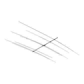
- Page 28 Boom and Element Positions - Dimensions in Inches...
- Page 29 Boom and Element Positions - Dimensions in centimeters...
- Page 30 NOTES:...
- Page 31 NOTES:...
-
Page 32: Technical Support
All products manufactured by DX Engineering are warranted to be free from defects in material and workmanship for a period of one (1) year from date of shipment. DX Engineering’s sole obligation under these warranties shall be to issue credit, repair or replace any item or part thereof which is proved to be other than as warranted; no allowance shall be made for any labor charges of Buyer for replacement of parts, adjustment or repairs, or any other work, unless such charges are authorized in advance by DX Engineering.
Need help?
Do you have a question about the SkyLark 2X7 and is the answer not in the manual?
Questions and answers