Table of Contents
Advertisement
Quick Links
Active Receive Antenna
Vertical Configuration
.
DXE-ARAV4-1P - Single Vertical Antenna
DXE-ARAV4-2P - Two Vertical Array Package (for use with NCC-2)
DXE-ARAV4-4P - Four Vertical Array Package
DXE-ARAV4-8P - Eight Vertical Array Package
Used under US Patent No. 7,423,588
DXE-ARAV4-INS-Revision 0a
© DX Engineering 2018
1200 Southeast Ave. - Tallmadge, OH 44278 USA
Phone: (800) 777-0703 ∙ Tech Support and International: (330) 572-3200
Fax: (330) 572-3279 ∙ E-mail: DXEngineering@DXEngineering.com
- 1 -
Advertisement
Table of Contents

Subscribe to Our Youtube Channel
Related Manuals for DX Engineering DXE-ARAV4-1P


Summary of Contents for DX Engineering DXE-ARAV4-1P
- Page 1 Active Receive Antenna Vertical Configuration DXE-ARAV4-1P - Single Vertical Antenna DXE-ARAV4-2P - Two Vertical Array Package (for use with NCC-2) DXE-ARAV4-4P - Four Vertical Array Package DXE-ARAV4-8P - Eight Vertical Array Package Used under US Patent No. 7,423,588 DXE-ARAV4-INS-Revision 0a ©...
-
Page 2: Location Considerations
(ARAV4) offer excellent receiving performance from 100 kHz to 30 MHz using a 3-piece aluminum antenna element only 102 inches long. DX Engineering’s unique design makes it vastly superior to traditional active antennas in both strong signal handling and feedline decoupling, providing significantly better weak signal reception due to lower spurious signal interference and reduced noise. -
Page 3: General Information
Most modern LED or LCD flat panel televisions are not broadband noise generators. Systems Packages There are 4 Vertical Active Receive system packages. (DXE-ARAV4-1P, -2P, -4P, -8P) DXE-ARAV4-1P Non-conductive mounting plate ... -
Page 4: Manual Updates
Every effort is made to supply the latest manual revision with each product. Occasionally a manual will be updated between the time your DX Engineering product is shipped and when you receive it. Please check the DX Engineering web site (www.DXEngineering.com) for the latest revision manual. -
Page 5: Technical Description
Easy Mounting and Installation Flexibility − Pre-drilled mounting plate and stainless steel U-Bolt Saddle clamps for mounting to your ground rod May be connected to a transceiver which lacks a receive antenna input using the optional DXE-RTR-2 Receive Antenna Interface for transceivers ... -
Page 6: Basic Tools Required
Installation Location The best place to install your active antenna is where you have the recommended space away from power lines and away from your house, tower or any structures which are excellent sources of noise. Even passive wiring in a building or metal fencing can act as a pickup antenna and re-radiate noise. -
Page 7: Low Frequency Response - Internal Jumpers
Low Frequency Response - Internal Jumpers The sensitivity response of the AVA2 system does not need to be changed for almost all installations. However, jumpers may be required to optimize or increase sensitivity or eliminate interference from strong broadcast stations. Set the jumpers to the lowest operating frequency desired only if high power broadcast interference is suspected. - Page 8 Assembly The assembly described is for a single DXE-ARAV4-1P. Use JTL-12502 - Jet-Lube SS-30 on the joints between the antenna elements and on all stainless steel hardware threads to prevent galling and to ensure proper torque. Orient the black mounting plate with the antenna mounting holes close to the top, as shown in Figure 1.
- Page 9 Antenna and Antenna Mounting Parts List Item Description Item Description Mounting Plate #6-32 x 3/4” Socket Head Cap Screw 1/2” Tube, Drilled #6 Flat Washer 3/8” Tube, Drilled #6-32 Nylon Lock Nut 1/4” Tube, Drilled #4-40 x 1/2” Socket Head Cap Screw #10-24 x 1-1/2”...
- Page 10 Bottom Antenna Element Assembly Refer to the drawing shown in Figure 3 and Figure 4 for the antenna assembly. Figure 4 Figure 4 Install 2 hex head bolts (#10-24 x 1-1/2” long) in the mounting plate using flat washers and hex nuts as shown in Figure 5, tighten in place.
- Page 11 Place a flat washer and a spacer on each of the hex head bolts. The bottom antenna element has larger holes on one side, these larger holes face the spacers. The bottom antenna element is installed so the spacers are inside of the element. Refer to Figures 3, 4, 5 and Figure 6 for details.
- Page 12 Mounting the V-Clamp with Tab to a Ground Rod Attach the wire with ring terminal using the hardware described in Figure 8 to the tab on the included DXE-SSVC-1PG. Figure 8 Install the customer supplied 1/2” OD to 3/4” ground rod where the Active Receive Antenna will be placed, You want approximately 2 feet of the ground rod or mounting mast above ground level to mount the antenna.
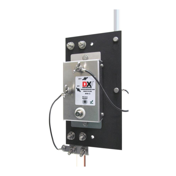
- Page 13 Mount the AVA-2 assembly to the ground rod as shown in Figure 10. Position the assembly on the ground rod and adjust the height so the ground rod top is not higher than the black insulated panel. This prevents unwanted interference with the active element. Tighten the two U-Clamps to hold the assembly in place.
- Page 14 Installing the upper two Antenna Elements The upper two elements are installed to the antenna element that is in place on the black mounting plate. 3/8” element fits inside the 1/2” element mounted to the black mounting plate. Use the #6 hardware and the included Allen wrench to secure this element in place.
- Page 15 Providing a Good RF Ground This active vertical antenna works well with just a single copper ground rod used as the mounting rod. You can test ground quality by listening to a steady local signal. Attach 15 feet of wire laid in a straight line away from the coaxial feedline.
-
Page 16: Coaxial Cable Feedline
To help decouple the feedline from radiated noise, bury the feedline for some distance from the antenna when the feedline reaches the ground. A DXE-RFCC-1 DX Engineering Receive Feedline Choke will also ensure feedline decoupling, which may be installed in-line, preferably at the station end. -
Page 17: Alternate Mounting
In a multi-element array, the internal jumpers are used to increase sensitivity at specific frequencies or to reduce interference from strong broadcast stations. When the ARAV4 is used in a DX Engineering Four Square Receiving Array or the Receive Eight Circle System, select a jumper setting at least 5% below the frequency in use. -
Page 18: Troubleshooting Information
DXE-ARAV4-1P Active Receive Vertical is probably operating normally. The DXE-ARAV4-1P is designed to be a very low to no gain, low noise system for greatly improved signal-to-noise performance over a very wide range of frequencies. The installation location should be away from towers, transmitting antennas, metal structures and metal fencing in order to take advantage of the DXE-ARAV4-1P Active Receive Vertical antenna capabilities. - Page 19 4 radials that are about 15 feet long to the negative terminal ground rod connection on the AVA-2. If this significantly increases signal level, then adding another ground rod and/or more radials, as described in the manual for the DXE-ARAV4-1P, should improve your signal results for all bands.
-
Page 20: Technical Support
All products manufactured by DX Engineering are warranted to be free from defects in material and workmanship for a period of one (1) year from date of shipment. DX Engineering’s sole obligation under these warranties shall be to issue credit, repair or replace any item or part thereof which is proved to be other than as warranted; no allowance shall be made for any labor charges of Buyer for replacement of parts, adjustment or repairs, or any other work, unless such charges are authorized in advance by DX Engineering.
Need help?
Do you have a question about the DXE-ARAV4-1P and is the answer not in the manual?
Questions and answers