Table of Contents
Advertisement
Quick Links
Advertisement
Table of Contents

Related Manuals for DX Engineering DXE-MBVE-1


Summary of Contents for DX Engineering DXE-MBVE-1
- Page 1 Multi-Band Vertical Antenna 160 through 10 Meters DXE-MBVE-1 DXE-MBVE-1-INS-Revision 16f © DX Engineering 2012 P.O. Box 1491 ∙ Akron, OH 44309-1491 USA Phone: (800) 777-0703 ∙ Tech Support and International: (330) 572-3200 Fax: (330) 572-3279 ∙ E-mail: DXEngineering@DXEngineering.com...
-
Page 2: Table Of Contents
Table of Contents Introduction Features Warning Tools Required DXE-MBVE-1 Parts List Manual Updates Suggested Parts Not Included Additional Material Needed, Not Supplied Installation Site Selection Radial System Mounting Pipe Assembly Radial Plate to Mounting Pipe Attaching Ground Radial Wires to the Radial Plate... -
Page 3: Introduction
Introduction The DX Engineering MBVE-1 is a fast taper 43 feet high multi-band vertical antenna system. The vertical antenna operates from 160 meters through 10 meters using a good quality outboard customer supplied tuner. There are no traps, coils or linear loading elements to rob power. Designed with 6063 corrosion-resistant aluminum tubing and stainless steel hardware, this antenna is very durable and attractive. -
Page 4: Tools Required
Every effort is made to supply the latest manual revision with each product. Occasionally a manual will be updated between the time your DX Engineering product is shipped and when you receive it. Please check the DX Engineering web site (www.dxengineering.com) for the latest revision manual. -
Page 5: Suggested Parts Not Included
Suggested Parts Not Included DXE-UN-43 - Multi-Band UNUN for Vertical Antenna Systems ® The DXE-UN-43 DX Engineering Multi-Band Vertical UNUN built with proven Maxi-Core Technology is a matching device specifically designed for application with non-resonant 43 foot tall vertical multi-band antennas. -
Page 6: Additional Material Needed, Not Supplied
Made from Laser Cut Stainless Steel with 20 Sets of Stainless Steel Radial Attachment Hardware. The DX Engineering Radial Plate is meant for those of you having a vertical antenna and want an easy, neat and effective way to connect those essential radial wires to your antenna system for the highest efficiency and strongest signals. -
Page 7: Installation
Grass will quickly overgrow the radials and it will be virtually impossible to see them. An article describing this process is available on the DX Engineering website in the Tech Info section. Radials can also be buried just under the surface by using a power edger to make a slit in the soil. -
Page 8: Assembly
Assembly The DXE-MBVE-1 shipping box contains the vertical tubing sections, an insulated U-channel, two DXE-SAD-200A 2" U-Bolt assemblies, a backing plate, a Tilt Base with two stainless steel V- Clamps, 15 stainless steel clamps, a black vinyl cap, and stainless steel hardware. -
Page 9: Radial Plate To Mounting Pipe
Note: The following assembly instructions are based on using a 2" OD Mounting Pipe, with the following options: DXE-RADP-3 Radial Plate, DXE-UN-43 UNUN, DXE-UN-BRKT Mounting bracket for the UNUN, and DXE-TCB- UNFK Feedpoint kit for the UNUN. Radial Plate to Mounting Pipe Install the optional DXE-RADP-3 Radial Plate (patented) on the 2"... -
Page 10: Attaching Ground Radial Wires To The Radial Plate
Figure 2. Additional hardware kits are available (DXE-RADP-1HWK) that contain 20 sets of Radial Plate Hardware. There are optional DX Engineering Radial Wire Kits available. DXE-RADW-500K/BD contains a 500 foot spool of 14 gauge copper stranded wire with black PVC insulation, 20 Terminal Lugs and 100 Steel or Biodegradable Lawn Staples. -
Page 11: Tilt Base To Mounting Pipe
Tilt Base to Mounting Pipe Install the Tilt Base to the 2" OD mounting pipe using the two DXE-SSVC-2P V-Bolt Saddle Clamps allowing approximately 4-1/2" clearance between the bottom of the tilt base plate, to the top of the DXE-RADP-3 Radial Plate as shown in Figure 3. The standard 1-1/2" galvanized water pipe (with its 1.9"... -
Page 12: Vertical Base Section
Vertical Base Section The base section is made up of an EXTREN® insulated mounting channel, a mounting plate with hardware, two 2" x 3/8" U-Bolt assemblies and the base antenna section which is 2" OD thick wall, 36" long with a hole drilled at bottom end for the feedpoint hardware. Using Figure 4, attach the aluminum backing plate to the back of the insulated channel. - Page 13 Install the lower section to the insulated channel using the two 2" x 3/8" U-Bolts, two saddle clamps, four 3/8" flat washers, four 3/8" split washers, and four 3/8" hex nuts as shown in Figure 6. The base section tube should extend 1-3/4" beyond the bottom of the U-bolt clamp. The feedpoint hardware should be coming out on the left side as you look at the lower section as shown in Figure 6.
-
Page 14: Base Section To Tilt Base
Base Section to Tilt Base Place the Lower Base Section into the holes of the mounted Tilt Base and loosely install the Tilt Base mounting hardware shown in Figure 7. Leave the flange nuts and Nyloc nuts slightly loose. Figure - 7 Using a wrench or nut driver, securely tighten the two Nyloc nuts at the bottom of the patented Tilt Base. -
Page 15: Assembling The Vertical Sections
Test the tilt function to ensure proper clearances. Standing in front of the Tilt Base, lift the antenna base section, slide it to the right, and let it down slightly until the lower outside bolt is resting in the pivot point. Then slowly tilt as shown in Figure 8. Make sure when you are tilting the antenna to lift, slide to the right, and then tilt. - Page 16 Deburring is a finishing method used in manufacturing. Our aluminum tubing is machine cut on both ends and machine slit on one end. Although DX Engineering manufactured aluminum tubing is deburred, you should further assure that there are no ragged edges or protrusions.
- Page 17 Locate the 15 Element Clamps. Element Clamp Quantity DXE-ECL-020 - Element Clamp DXE-ECL-040 - Element Clamp DXE-ECL-060 - Element Clamp DXE-ECL-10SS - Element Clamp DXE-ECL-12SS - Element Clamp DXE-ECL-16SS - Element Clamp DXE-ECL-20SS - Element Clamp DXE-ECL-24SS - Element Clamp DXE-ECL-28SS - Element Clamp Figure 9 Refer to Figure 11 for element clamp sizes and locations.
- Page 18 The top section may be adjusted to vary the length for fine adjustment if necessary. Overall height is 43 Feet Figure 11 - Finished Antenna Assembly (Drawing not scale) - 17 -...
-
Page 19: Mating The Vertical Sections To The Tilt Base
Mating the Vertical Sections to the Tilt Base CAUTION: Attempting final assembly without proper precaution can be dangerous. You should have someone help you steady the vertical antenna sections during mating with the base section. Note: A pair of sawhorses or ladders should be used to support the vertical sections during assembly with the Tilt Base and whenever the vertical is tilted down. -
Page 20: Assembling The Unun Mounting Bracket
The antenna mounting channel must be kept in parallel alignment with the tilt-base plate to prevent binding until it is positioned in the tilt-base. Once the antenna is vertical, lift and slide the antenna to the left toward the tilt-base mounting pipe to allow the two parts of the tilt-base to line up and drop down into the slots. -
Page 21: Installation Of Unun Assembly To Antenna
Installation of UNUN Assembly to Antenna Lower Section The completed UNUN and UNUN Mounting Bracket assembly are mounted to the antenna lower section. To allow easy installation of the UNUN Bracket to the lower base section, open the upper and lower custom studded element clamps as shown in Figure 13. Figure 13 Position the UNUN Mounting Bracket so the bottom element clamp is located between the feedpoint hardware and the U-Bolt as shown in Figure 14. - Page 22 Once in position, re-insert the clamp ends into the worm drive of the clamps and using a flat blade screwdriver or nut driver, snug them up as shown in Figure 15. Note position of lower clamp is between the feedpoint hardware and the U-Bolt. Figure 15 - 21 -...
-
Page 23: Feedline Connections
Position the UNUN so it faces forward. Tighten the Upper and Lower Studded Clamps and Tighten the Nyloc Nuts on the Upper and Lower Clamps Figure 16. Figure 16 Feedline Connections The DXE-UN-43 UNUN is attached to the feedline antenna connection using the DXE-TCB- UNFK - UNUN Feed Point Connection Kit which contains two pre-drilled copper tinned braids for connection to the vertical antenna system. - Page 24 Note: Ensure the braid connection to the Radial Plate does not interfere with the tilting process. Figure 17 Your coaxial cable from the radio connects direct to the SO-239 connector on the DXE-UN-43 UNUN. Weatherproof this coaxial connection using TRM-06132 - Scotch® Super 33+ and DXE- 3M2155 - 3M Temflex™...
-
Page 25: Coaxial Cable And 160 Meter Notes
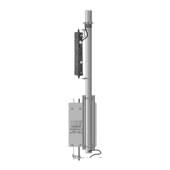
Coaxial Cable and 160 Meter Notes Let's look at 160 meters in more detail. A 43 foot vertical antenna is a short antenna for 160, but it will get you on the air. In this instance, coaxial cable type is a very important item to consider. DX Engineering recommends a length of 150 feet of DXE-213U an RG-213/U to give most tuners the ability to match the antenna on the lower frequency bands where most tuning problems are encountered. - Page 26 Figure 18b - Completed Base Assembly for Reference - 25 -...
-
Page 27: Tuning The Vertical
Tuning the Vertical Antenna System The use of a customer supplied, high quality, outboard tuner is required for any multi-band trapless vertical antenna system. The tuner should be capable of tuning the wide range of impedances presented by the antenna and coaxial cable at all the operating frequencies. Tuners of this type generally have a good quality variable roller inductor and at least one large variable capacitor for fine tuning. -
Page 28: Guying A Vertical Antenna System
Guying a Vertical Antenna System Guying of vertical antennas is always recommended for stability. However, if your area encounters severe wind velocities or icing conditions, simple guying will reduce the possibility of failure. Using the DXE-GUY kits, you can install four guy ropes starting approximately 1/2 the way up the vertical antenna system to ground level. -
Page 29: Optional Accessory Items
DXE-RADP-3 - Radial Plate, Stainless Steel with 20 Sets of SS Radial Attachment Hardware The patented DX Engineering Radial Plate is meant for those of you that have or are building a quarter wave vertical antenna and who want an easy, neat and effective way to connect those essential radial wires and the coax to your vertical antenna for the lowest takeoff angle and strongest signals. - Page 30 A no compromise system! A Bias Tee is included with this special package for supplying the 12 Vdc power through the coaxial cable from your radio shack to the remote tuner. Works on all DX Engineering, Zero-Five, MFJ and Hy-Gain 43 foot vertical antennas.
- Page 31 SUM-900031 - Automatic Wire Stripper/Crimper/Cutter, 24-10 Ga. Our DX Engineering wire stripper uses a spring-loaded design to make quick work of wires ranging from 24 to 10 gauge. Just insert the wire, squeeze the handle, and listen for the click. That’s the sound of another perfect wire stripping job performed in about 2 seconds- a fraction of the time it takes your pocket knife to do the same job.
-
Page 32: Technical Support And Warranty
Warranty All products manufactured by DX Engineering are warranted to be free from defects in material and workmanship for a period of one (1) year from date of shipment. DX Engineering’s sole obligation under these warranties shall be to issue credit, repair or replace any item or part thereof which is proved to be other than as warranted; no allowance shall be made for any labor charges of Buyer for replacement of parts, adjustment or repairs, or any other work, unless such charges are authorized in advance by DX Engineering.
Need help?
Do you have a question about the DXE-MBVE-1 and is the answer not in the manual?
Questions and answers