Bionet Cardio P1 Operation Manual
Hide thumbs
Also See for Cardio P1:
- Operation manual (123 pages) ,
- Service manual (53 pages) ,
- Quick manual (6 pages)

Related Manuals for Bionet Cardio P1


Summary of Contents for Bionet Cardio P1
- Page 1 Electrocardiograph Cardio P1 Operation Manual Ver. 1.02 2024. 02. 01 www.ebionet.com Copyright © 2023 By Bionet Co., Ltd. All rights reserved...
- Page 2 REVISION HISTORY Revision No. Date Contents Page 1.00 2022.05.24 First Written Modified to model name Cardio P1 Full translation reflected 1.01 2023.04.04 Change logo Correction of incorrect information (delete ‘LAN network, WLAN network’) Update European Sales email and web 1.02 2024.02.01...
- Page 3 Federal law restricts this device to sale by or on the order of a physician Note The product does not have shelf life. Its expected use life is 3 years. After 3 years, though the product still works normally, it is recommended to have it checked by Bionet. 2024.02 3 / 122...
- Page 4 Tel : +49-30-240-374-52 E-mail : be@ebionet.com Website: www.bionet-europe.com ※ In the event of a malfunction or failure, contact Service Dept. Of Bionet Co., Ltd. along with the model name, serial number, date of purchase and explanation of failure. 2024.02 4 / 122...
- Page 5 - Mishaps such as dropping the product. - Using the third party replacements or options not specified by our company. - Non-Bionet technicians or agency technicians in the process of repair. 3. Other cases - Breakdowns by natural disasters (fire, salt damage, flood damage, earthquake, etc.) - When a consumable part has reached the end of its life (accessories) 2024.02...
- Page 6 V 1.02 Warnings, Cautions, and Notes The following terms are used throughout this manual to emphasize important and critical information. You must read these statements to help ensure safety and to prevent product damage. l The manufacturer or the product distributor is not liable for any loss or damage to the product caused by incorrect use or negligence in product maintenance.
- Page 7 DO NOT connect power DO NOT disjoint or until the product is disassemble the equipment. completely installed. (Bionet is not liable for broken products caused by It may cause damage to attempted disassembly.) the product. 2024.02 7 / 122...
- Page 8 Please note the following precautions before using the product. Is the power supply cord proper? • 1. Cardio P1 : 5Vdc, Max. 0.5A Is every cord connected properly to the product? • There is a risk of electric shock if the Rest stand of the equipment is damaged or not be •...
- Page 9 V 1.02 as relocating or re-orienting the equipment. Caution Warning: MR-unsafe! DO NOT expose the device to a magnetic resonance (MR) environment. The device may present a risk of projectile injury due to the · presence of ferromagnetic materials that can be attracted by the MR magnet core.
- Page 10 V 1.02 Safety Messages The following messages are applied throughout the product. Certain statements may also appear elsewhere in the manual. WARNING: ACCIDENTAL SPILLS — If the equipment is penetrated with liquid, take it out of service and have it checked by a service technician before using it again. DO NOT allow liquids to enter the equipment to prevent electric shock or equipment malfunction.
- Page 11 V 1.02 levels of electromagnetic radiation. WARNING: Use of this equipment adjacent to or stacked with other equipment should be avoided because it could result in improper operation. If such use is necessary, this equipment and the other equipment should be observed to verify that they are operating normally. WARNING: EXPLOSION HAZARD - Do NOT use in the presence of flammable anesthetics vapors or liquids.
- Page 12 V 1.02 For safety reasons, all connectors for patient cables and lead-wires are designed to prevent inadvertent disconnection, should someone pull on them. For devices installed above the patient, adequate precautions must be taken to prevent them from dropping on the patient. WARNING: TREADMILLS - Avoid rapid changes in treadmill speed and/or grade during a stress test.
- Page 13 If you have questions concerning the disposal of the product, please contact Bionet or its distributor. CAUTION: EQUIPMENT DAMAGE — Equipment intended for emergency application must not be exposed to low temperatures during storage and transport to avoid moisture condensation at the application site.
- Page 14 V 1.02 Safety Symbols Symbols Contents Attention Consult accompanying documents Consult Instructions for Use: This symbol advises the reader to consult the operating instructions for information needed for the proper use of the equipment. Safety Sign To signify that the instruction manual must be read. Reading the instruction manual before starting work or before operating equipment.
- Page 15 V 1.02 Manufacturer Authorized Distributor in the European Community Waste of electrical and electronic equipment must not be disposed as unsorted municipal waste and must be collected separately. Please contact an authorized representative of the manufacturer for information concerning the decommissioning of your equipment. MR Unsafe: DO NOT use this equipment in all MR environment.
-
Page 16: Table Of Contents
V 1.02 Table of Contents Chapter 1. General Rules ..................18 1) Product Overview ............................18 2) Recording ECGs during Defibrillation ....................20 3) Product Characteristics ..........................20 4) Product Configuration ...........................22 5) Installing System ..............................30 6) System the Start...............................36 Part I. Using ECG .................. 45 Chapter 2. - Page 17 V 1.02 2) Regular Examination ........................... 105 3) Simple Troubleshooting ..........................105 4) Manufacturer Declaration ......................... 111 Chapter 6. Product Specifications ..............118 Specifications or functions indicated on user manual are subject to change without notification for the improvement of product. 2024.02 17 / 122 Doc.
-
Page 18: Chapter 1. General Rules
Sending and receiving ECG data to and from the Hospital Information System is optional. The Cardio P1 is intended to be used by personnel trained in hospitals or medical professional facilities under the direct supervision of a licensed healthcare practitioner. - Page 19 Do not expose the Cardio P1 to liquids. d. The Cardio P1 should not be used in the presence of flammable liquids or gases, dust, sand, or any other chemical substances.
-
Page 20: Recording Ecgs During Defibrillation
If such use is necessary, this equipment and the other equipment should be observed to verify that they are operating normally. Only use the Cardio P1 with the power supply provided. Attempted use with other power sources may cause irreparable damage and invalidate the warranty. - Page 21 V 1.02 - The 12 channel rhythms are continuously printed simultaneously in real time. - The heart rate, PR interval, RR interval, QRS interval, QT interval, QTc interval, P-R-T axis, and SV1/RV1/R+S size required for diagnosis are automatically calculated and provided on the report along with the ECG.
-
Page 22: Product Configuration
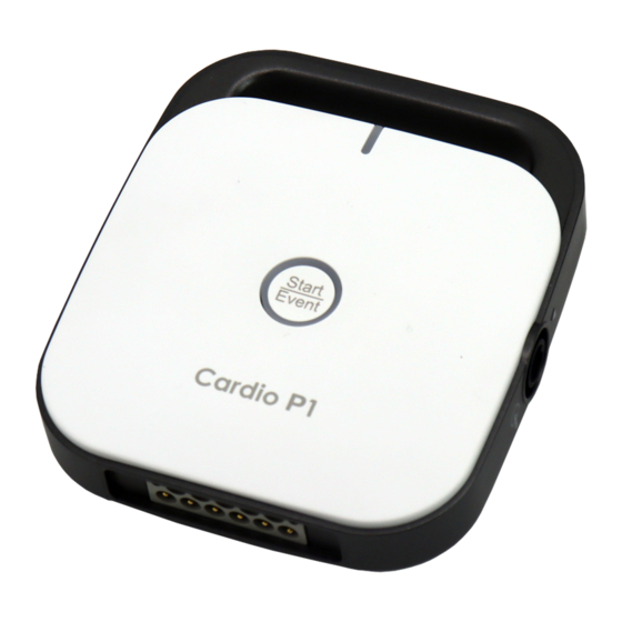
V 1.02 4) Product Configuration The Cardio P1 system is comprised of the following components. Cardio P1 1) CardioSync - Software that analyzes and records the measured ECG - Installed on a PC. 2) Cardio P1 - Device to ECG measurement Basic Configuration and Accessories Make sure to open the package box and see if the following components are contained. - Page 23 V 1.02 ① Body (1ea) - Cardio P1 90.75(W) x 103.5(H) x 24.93(D)mm ② Patient Cable (1ea) - Length 1,400mm (Max) ③ Power (USB Data) Cable (1ea) - Length 2,450mm (Max) ④ Limb Electrodes (1set) ⑤ Chest Electrodes (1set) ⑥ Hanger (1ea) ⑦...
- Page 24 V 1.02 ▣ Bottom View ① ① ID Label : Part to attach ID Label ▣ Side View ① ① Power (USB Data) Cable Connection Port 2024.02 24 / 122 Doc. # : BN-CP1-OPM-301...
- Page 25 Bionet. Caution When using the device (Cardio P1) connected to the PC, the mouse may malfunction. In this case, reconnect the device's power (USB) cable to the PC. 2024.02 25 / 122 Doc.
- Page 26 V 1.02 CardioSync Main Screen Graphic Display Window Auto and Event Key 2024.02 26 / 122 Doc. # : BN-CP1-OPM-301...
- Page 27 ⑥ Display the real-time diagnosis name display ⑦ Indicate Retry queue (sending failure list management) icon ⑧ Access status of external devices (barcode reader) ⑨ Access status of Cardio P1 ⑩ Menu button for network connection status and setup ⑪ Button for expand/collapse Side Menu ⑫...
- Page 28 V 1.02 Button for moving to File Print button Print setup menu button Setup menu button Display manual button Show manual 10) Minimize button 11) Show contact us 12) Logout button 13) Close button ⑬ Side Menu bar Indicate heart rate Lead Fault status display and lead position display window button AUTO button Menu button for indicating ECG record mode (one of the 10s, 1m, 3m, 5m, 10m, 20m...
- Page 29 V 1.02 Function Key Panel ② ① ③ ▣ Button Auto / Event. 1. Long Press (more than 3 seconds) Perform the operation that is the most frequently performed in the saving, transmission, and printing of data in the ECG diagnosis test ①...
-
Page 30: Installing System
5) Installing System Installation Precautions Note the following when installing the Cardio P1 - Use the equipment within the ambient temperature of 10~40℃ and humidity of 30~85%. - Check the connection of the power cord and handle the patient cable with care. - Page 31 V 1.02 < Step 1> < Step 2 > <Step 3 > 2024.02 31 / 122 Doc. # : BN-CP1-OPM-301...
- Page 32 V 1.02 < Step 4 > < Step 5 > ④ Execute “setup.exe” or “Cardio P1 ECG_X.XX.XXX_YYYYMMDD.msi” under your CD-ROM drive, download folder or USB memory. ⑤ Follow each instruction on each step. 2024.02 32 / 122 Doc. # : BN-CP1-OPM-301...
- Page 33 V 1.02 < Step 1 > < Step 2 > < Step 3 > 2024.02 33 / 122 Doc. # : BN-CP1-OPM-301...
- Page 34 Power Connection Plug the power (USB data) cable into the USB port of the PC and the side connection cord of the Cardio P1 and the device will work. Patient Cable Connection - Connect the patient cable to the patient cable connection port located on the bottom of the main unit.
- Page 35 Repair or disassembly of the equipment can only be performed by those who have product repair qualifications recognized by Bionet. Bionet is not liable for any problems arising from the disassembly and modification of equipment by an unqualified person. General Precautions...
-
Page 36: System The Start
V 1.02 6) System the Start After everything is ready, run the software and you will see the login screen as shown. Login Enter your ID and password. Roles and privileges are assigned to individual users and may affect each user's scope of access to areas of the workflow and available functions. - Page 37 V 1.02 Click the items to inspect on the screen to move to the default screen on the selected menu. The figure below shows the initial ECG screen that moves when the ‘ECG’ menu is selected. If you know the following on the ECG initial screen, you can use it more conveniently. Menu explanation Enter patient information or confirm contents...
- Page 38 V 1.02 Patient management screen Worklist screen File screen Print execution Print setting System setting Help Company information. Minimize button Fix the screen. Log out End of the program. Setup or indicate recording mode (Displayed as 10s, 1m, 3m, 5m, 10m, 20m, 30m) Heart rate display Confirm lead fault information Auto Button...
- Page 39 Indicate or setup the print speed Indicate or setup the signal size Set filter value display window Note Function keys available in Cardio P1 - F9 Button : Auto - F10 Button : Save - F11 Button : Export - F12 Button : Print The following is the patient examination data management screen that moves when the ‘Patient...
- Page 40 V 1.02 Followings are recommended to know on the exam request data managing screen for more convenient usage. Menu Explanation Search for data by entering search conditions Move to the exam screen Add patient information Edit patient information Delete patient information Check measurement information / Compare two measurement values Note Applicable matters when editing patient information.
- Page 41 V 1.02 Following is the ECG data file managing screen when selecting ‘Worklist’ menu. Followings are recommended to know on the data file managing screen for more convenient usage. Menu Explanation Search for data after entering searching conditions Move to the exam screen Get Worklist Menu button that appears when PACS or GDT is connected Search condition setting...
- Page 42 V 1.02 Following is the ECG data file managing screen when selecting ‘File’ menu. Followings are recommended to know on the data file managing screen for more convenient usage. Menu Explanation Search for data after entering searching conditions File export File import File preview Check patient information...
- Page 43 V 1.02 file The following is the Retry Queue data management screen that moves when (Retry Queue icon) is selected. The Retry Queue manages error data when an error occurs during transmission to the server. Followings are recommended to know on the Retry Queue managing screen for more convenient usage.
- Page 44 V 1.02 Menu Explanation Send selected data Delete selected data Note icon is indicated on the right top corner only if there is an error while sending files. 2024.02 44 / 122 Doc. # : BN-CP1-OPM-301...
-
Page 45: Part I. Using Ecg
V 1.02 Part I. Using ECG 2024.02 45 / 122 Doc. # : BN-CP1-OPM-301... -
Page 46: Chapter 2. Ecg Recording Preparation
V 1.02 Chapter 2. ECG Recording Preparation 1) Attaching the Electrodes When you touch (Lead Fault Information) located in the center of the menu bar at the top of the ECG Main screen, a picture showing where to attach the electrodes is displayed. -
Page 47: Connecting Electrodes
Connect the patient cable to the port on the right side of body and connect limb electrodes to the terminals of RL (N), LL (F), RA (R), and LA (L) of patient cable connected in the Cardio P1 and chest electrodes to the terminals V1 (C1), V2 (C2), V3 (C3), V4 (C4), V5 (C5) and V6 (C6). -
Page 48: Recording Ecg
If the ECG signal is not accurately acquired even after you try all the solutions above, the patient cable may be non-conforming. Contact Bionet's service center. 3) Recording ECG - Enter accurate patient information. -
Page 49: Basic Setup
V 1.02 abnormal or there is too much noise. - If the waveform displayed on the LCD screen is normal, press the [AUTO] key to record the ECG. - Press the [STOP] key to stop printing or saving the ECG results. 4) Basic Setup General Information When you turn on the equipment, top and bottom menu bars and graphic window appear on... - Page 50 V 1.02 Start the test after confirming that the signal is correctly transmitted from all leads. The screen output background color of the ECG waveform can be selected from either white or black and can be changed in the Setup à ECG à Display à Background menu. In the black background, the waveform is drawn without a grid as shown below.
- Page 51 V 1.02 Patient ID Enter a unique number used in the hospital to classify patient medical data. Touch the input field of ID to display the keypad window consisting of alphabets and numbers, and use it to enter patient ID. Note You cannot use ., “, <, >, ?, /, *, |, :, \ &...
- Page 52 V 1.02 Enter the patient's age directly. Enter the age of pediatrics or adults. Enter the age in weeks or days if you cannot enter the age in years. Note - Age is automatically calculated when the date of birth is entered. - If age is not entered, an adult diagnosis is provided.
- Page 53 However, since the default setting of the entry method of each product may be different, check the method supported by Bionet before using them. Entry methods supported by Bionet products: International standard and USB The products that have been tested by connecting to Bionet equipment are listed below. 2024.02 53 / 122 Doc.
- Page 54 V 1.02 Manufacturer Product name Product Image Symbol LS-2208 Z-3110 ZEBEX Honeywell MS5145 Honeywell DS2208 Note Each barcode reader has a product-specific initialization code. Be sure to read the user manual of the product and check the entry method before initializing 2024.02 54 / 122 Doc.
- Page 55 V 1.02 Measurement Time Setting The measurement time setting is used when you want to perform a 10-second recording measurement or output 1CH for a long time. It can be set to 1, 3, 5, 10, 20, or 30 minutes, and at this time, it is output with the set lead. Note Real-time diagnosis is issued by referring to the leads of the Long-term ECG.
- Page 56 V 1.02 Output Speed Adjust the width of the output signal for screen output and printout. The available values are 5mm/sec, 12.5 mm/sec, 25mm/sec, 50mm/sec, and 100mm/sec. 25mm/sec means that the ECG signal for 1 second is recorded with a length of 25mm. Note - When you set the recording mode to 3, 5, 10, 20 and 30min, the signal is always printed at 12.5mm/sec.
- Page 57 V 1.02 Setup Signal Scale If the scale of output signal is too high and is duplicated with signals in neighboring channel, or if the scale of output signal is too low making it difficult to decipher, this function is used to adjust the signal scale.
- Page 58 V 1.02 Setup Print Printer Setup the printer to print. If you click the Properties button, you can use the normal Windows printer settings. 10s Print Form Set the diagnosis print format. 2024.02 58 / 122 Doc. # : BN-CP1-OPM-301...
- Page 59 V 1.02 Form Output form Explanation 10-second resting ECG recording: I, II, and III in the first 2.5 seconds; aVR, aVL, and aVF in the next 2.5 second; V1, V2, and V3 in the next 2.5 3CH+3 seconds; and V4, V5, and V6 in the next 2.5 seconds. The 3-lead rhythm is recorded at the bottom for 10 seconds.
- Page 60 V 1.02 It outputs the representative bit and each diagnostic parameter and ST Map outputs the ST map. ST Map Type When selecting the bit form as ST Map, you can select the style of drawing the ST Map. Output form Explanation The representative beat and each diagnostic parameters are printed, ST Map (B)
- Page 61 V 1.02 Note Real-time diagnosis is based on the lead of the Long Term ECG. Normally, the lead II is the largest, so you can set the lead II, but if the waveform is small, select the other lead with the largest and best waveform. Print Page Settings related to the printout Page(s)
- Page 62 V 1.02 Interpretation Select whether or not to output diagnostics when outputting records. Comments Select whether to output the observations added to the record results. HRV parameters Select whether to output HRV parameters when outputting records. Diagnosis Caps Lock When outputting a record, the diagnosis name is output in uppercase. Masking Set to de-identify patient information when printing.
- Page 63 V 1.02 Diagnosis Print Format (3CH + 3RHY) Diagnosis Print Format (3CH + 1RHY) 2024.02 63 / 122 Doc. # : BN-CP1-OPM-301...
- Page 64 V 1.02 Diagnosis Print Format (6CH + 1RHY) Diagnosis Print Format (12CH) 2024.02 64 / 122 Doc. # : BN-CP1-OPM-301...
- Page 65 V 1.02 Diagnosis Output Form (6CH+1(ST)-Dot) Diagnosis Print Format (6CH+1 (ST)) 2024.02 65 / 122 Doc. # : BN-CP1-OPM-301...
- Page 66 V 1.02 Diagnosis Print Format (BEAT REPORT-TEXT) Diagnosis Print Format (BEAT REPORT-VECTOR) 2024.02 66 / 122 Doc. # : BN-CP1-OPM-301...
- Page 67 V 1.02 Diagnosis Print Format (BEAT REPORT-GUIDE) Diagnosis Print Format (BEAT REPORT-ST Map (D)) 2024.02 67 / 122 Doc. # : BN-CP1-OPM-301...
- Page 68 V 1.02 Diagnosis Print Format (BEAT REPORT-ST Map (B)) 2024.02 68 / 122 Doc. # : BN-CP1-OPM-301...
- Page 69 V 1.02 * Explanation of BEAT REPORT Variables PR: PR Interval PA: Amplitude of P Wave (P Amplitude) PD: Duration of P Wave (P Duration) QA: Amplitude of Q Wave (Q Amplitude) QD: Duration of Q Wave (Q Duration) RA: Amplitude of R Wave (R Amplitude) RD: Duration of R Wave (R Duration) SA: Amplitude of S Wave (S Amplitude) SD: Duration of S Wave (S Duration)
- Page 70 V 1.02 Note Dextrocardia Normally, the heart is located in the left chest. However, there are cases where the heart is located in the right chest, which is called Dextrocardia. You may suspect Dextrocardia in the following cases: - If P, QRS and T are all reversed in Lead I - If aVR and aVL are switched, and lead II and III are switched - If R wave becomes smaller from V1 to V6 in chest lead For Dextrocardia patients, change the electrode positions and measure as follows to obtain...
-
Page 71: Disclosure
V 1.02 5) Disclosure Touch the button on the menu bar at the bottom of the ECG main screen to switch to Disclosure screen. Disclosure is a function that stores ECG data in the equipment memory and shows it when executed. In the Disclosure screen: The pre-stored 30 minutes of ECG data are displayed in 1CH. - Page 72 V 1.02 ⑥ Touch the button to update EKG Wave data from the start of Disclosure to the present time. ⑦ Switch to Live mode button ⑧ Select output lead ⑨ Select the output size ⑩ Output speed selection Refer to the following description for Disclosure Live mode screen. ECG Wave data is drawn in real time in the grid-marked area at the bottom of the screen.
- Page 73 V 1.02 Irregular Irregular RonT R on T Arrhythmia Template Diagnostic Description PVC Bigeminy Occurs when two or more bigeminal cycles (a ventricular beat followed by a non-ventricular beat) are detected. PVC Trigeminy Occurs when two or more trigeminal cycles (a ventricular beat followed by two non-Ventricular beats) are detected.
-
Page 74: One-Key Diagnosis (Auto Key)
V 1.02 Note The diagnosis provided by Cardio P1 must be confirmed by a qualified medical professional. 6) One-key Diagnosis (AUTO key) Press the [AUTO] key shortly to diagnose the ECG acquired during the set duration, and to save, transmit, and print the result. It functions according to the [AUTO] key settings set in System General Setup. - Page 75 V 1.02 If you select the 'Settings' button on the left menu bar of ECG, you can change the setting conditions. You can setup ECG related setups in each group. ‘Default’ button is shown on the setup currently shown on the screen. If saving changed information after all the setups, select ‘Ok’...
- Page 76 V 1.02 Record Make settings related to ECG measurement. You can set the lead fault, heartbeat alert, and preview as follows. Setting Lead Fead Lead Fault A lead fault may occur if the lead connection of the patient cable is unstable. Set whether or not to display the Lead Fault message in this case.
- Page 77 V 1.02 QRS Sound You can set the sound output according to the QRS beat. When it is set to On, a sound is generated from the QRS beat, and when it is Off, no sound is produced. Preview Preview shows the results of measurement in advance after performing the diagnosis with record, auto and network keys.
- Page 78 V 1.02 background color You can set the background for drawing the graph. In the case of Grid, a red grid and black signal are displayed on a white background, and in the case of Black, a green signal is displayed on a black background. Demo Setup or discharge demo functions.
- Page 79 V 1.02 Muscle Muscle filter is EMG filter as a signal that occurs in muscle or organ of a patient. If measuring ECG with patients with especially high EMG, ECG is not well recorded. Therefore, it is required to remove noise. If applying ECG filter, ‘off’ can be selected if not using ‘on’. Setup of all the applied filters is indicated at the left bottom corner of output form.
- Page 80 V 1.02 are set to be 60msec. In case of ‘80msec,’ J points are set to be 80msec. Real Time Diagnosis This is the setup for real-time automatic diagnosis on the ECG main screen. If detecting arrhythmia in the standby condition without recording, you can set it to ‘ON’ to show the diagnosis name.
- Page 81 V 1.02 General Language Select the language and touch [OK]. Note Even if the set language is not English, some terms, such as diagnosis names, may be shown in English. Start Option This is to setup the screen shown when the equipment turns on for the first time. Make sure to select the default screen with function that is frequently used among main, ECG, Patient, file and worklist.
- Page 82 V 1.02 - Off : Return to the measurement screen after the end of the test - Worklist: After the inspection is finished, it goes to the Worklist screen. - Review: Go to the Review screen after completing the test. Date Format Setup the date format.
- Page 83 V 1.02 Enter doctor name. Location Information Enter location name. User List Manage who will use the program. User Add Click Add user to enter a new user. User Name : Enter the user name Password : Enter the user's password. Retype Password: Confirm by re-entering the user password.
- Page 84 V 1.02 Role : Enter the user's permissions. In case of ‘Admin,’ user has authority over all functions, such as system setting, diagnosis setting, inspection, general setting and etc. In case of ‘Physician,’ user has authority over diagnosis settings, tests, general settings. In case of ‘Technician,’...
- Page 85 V 1.02 Single Sign On Because single sign-on can compromise security, Bionet recommends this setting only for the devices used single or a limited user. Activate it to enable system authentication of user ID and password. If it is set, no login is required at the start of the program because user authentication is carried out by the equipment.
-
Page 86: Part Ii. Data And System Management
V 1.02 Part II. Data and System Management 2024.02 86 / 122 Doc. # : BN-CP1-OPM-301... -
Page 87: Chapter 3. Exam-Requested Data Management
V 1.02 Chapter 3. Exam-requested Data Management 1) Screen Description ① ② ③ ④ ⑤ ① Top list search menu button ② Search condition setting button ③ Retrieve patient information button ④ Delete selected information button ⑤ Test progress button 2) Function Search You can enter search conditions by clicking the search condition menu at the top right of the... - Page 88 V 1.02 Touch the magnifying glass button at the top left of the screen to enter a search condition. Touch Search Item to enter ID, Name, Accession No. View patient information You can check or change patient information in the selected list. Get inspection information Get the latest inspection information from the PACS server or GDT server.
-
Page 89: Chapter 4. Manage Data Files
V 1.02 Chapter 4. Manage Data Files 1) Screen and Function Setup ① ② ③ ④ ⑤ ⑥ ① File list search menu button ② View selected patient information button ③ Selected file preview button ④ File export button ⑤ File import button ⑥... - Page 90 V 1.02 Note Care has to be taken as deleted data cannot be restored. View Files Preview of selected files It is available to change and print speed, gain, and print form on the preview screen. View Patient Information It is available to confirm or change patient information on selected files. Note When recording ECG for 10 seconds, adult diagnosis is applied to those aged 16 or above.
-
Page 91: Setup
V 1.02 3) Setup If clicking ‘setup’ button on the menu, ‘file setup’ window pops up. Connect to Server PACS, GDT, Web server or EMS/HIS can be selected from the menu to select the server interlocked with the equipment. After selecting the type of server to be linked, select the ‘Edit’ button to display the server setting window. - Page 92 A. None No connection with the server. B. PACS Setting Device Information AE Title, Port Enter information such as AE Title and Port of Cardio P1. Modality Enter the Modality of ECG 2024.02 92 / 122 Doc. # : BN-CP1-OPM-301...
- Page 93 V 1.02 Worklist Server Settings IP, Port, AE Title Worklist Enter information such as the server's IP, AE Title, Port, etc. Server connection check You can check the worklist server connection by pressing the 'Echo Test' button after entering the information of the worklist server. Click the "Ping Test" button to check the task list and ping.
- Page 94 V 1.02 enter the worklist screen. Store Server Settings IP, Port, AE Title Enter information such as IP, AE Title, and Port of the Store server. Echo Test & Ping Test After entering the store server information click the “Echo Test” button or “Ping Test” button to check the connection to the store server.
- Page 95 A screen for setting related settings such as Work type, GDT Directory, Component name, File name, Image type appears. Work type It sets how the GDT function of the device operates. - Server: Cardio P1 receives requests and commands. - Client: Cardio P1 sends requests and commands. 2024.02 95 / 122...
- Page 96 V 1.02 Directory Enter the format of sharing folder information and date information to be used by GDT protocol. Path Enter the shared folder path to be used by the GDT protocol ex) \\192.168.30.162/GDTShare User ID & Password Enter shared folder access ID & password Date Date information format setting YYYYMMDD, MMDDYYYY, DDMMYYYY...
- Page 97 V 1.02 Receiver (EMR/HIS) Name: Enter the EMR name to use for the GDT protocol Short Name: Enter EMR abbreviation Sender (Device) Name: Enter the device name to use for the GDT protocol Short Name: Enter device abbreviation File Type Select the image format of the data file to be shared with the GDT protocol.
- Page 98 V 1.02 The web address to connect to. User ID to use on the web to connect to. This is the user password to use on the web to access. Verify After entering the Web server information click the “Verify” button to check the connection to the Web server.
- Page 99 Choose a file type to decide which files to share. WorklistCom To manage worklists using WorklistCom provided by Bionet, check ‘Connect to Bionet WorklistCom’. After entering the IP of the target using WorklistCom, you can check whether the verification button works normally by pressing the 'Verify' button 2024.02...
- Page 100 The Dicom format with MFER, XML, and Image format is RAW can only support a 10-second ECG test. Auto Delete after Transmission Set whether to delete the file in Cardio P1 after completing the file transfer to the server. When set to ‘On’, the device file is deleted after file transfer. Note The Delete option only applies when sending to the server.
-
Page 101: Transmit Data
V 1.02 Dicom File Creation Option Image Format Determines the image format to use when transferring Dicom files. You can choose from PDF, BMP, JPEG, and RAW. Window Width Specifies the image size in JPG, BMP format. Window Center Specifies the center of the image in JPG, BMP format. 4) Transmit Data 2024.02 101 / 122... -
Page 102: Import Data
Files failed to be sent are indicated on ‘Retry Queue’ screen. Such files can be re-sent. 5) Import Data It is available to import bionet format files saved on USB memory by using ‘Import’ button on the control panel from file screen. - Page 103 V 1.02 If clicking ‘open’ button after selecting data to be loaded on the equipment, data can be loaded on the equipment. Note Only the files in following formats can be imported: è ekgx, ltecg, stecg 2024.02 103 / 122 Doc.
-
Page 104: Chapter 5. System Management
Chapter 5. System Management 1) Maintenance and Cleanliness Keep Cardio P1 equipment and handles clean. Avoid damaging or contaminating the equipment using the methods recommended below. If you use the substances - including not allowed substances - that can damage on the product, warranty is not applied even during the warranty period. -
Page 105: Regular Examination
Service Center, or the store where you purchased the product. 2) Regular Examination As with any other medical equipment, have your Cardio P1 regularly safety inspected once a year. Refer to the service manual provided by Bionet for inspection items. - Page 106 V 1.02 System Message Message Causes Solution "Do you want to save new disclosure data from now? Click Yes to When data is stored in Click 'Yes' if you want to delete discard the old data Disclosure, when there is existing data, or 'No' if you and save the new one.
- Page 107 V 1.02 File Message Causes Solution "The study record being exported will be Click 'Yes' if you wish to cancel When the Cancel button is discarded. or 'No' if you do not wish to pressed when exporting a file Are you sure to cancel.
- Page 108 V 1.02 Setup Message Causes Solution When device AE Title is Please check device AE Enter the correct value and try entered incorrectly when title. again setting PACS When device port is entered Please check device Enter the correct value and try incorrectly when setting up port.
- Page 109 Password and retry. Confirmation success when Verification successful. interworking with Web Server and EMR/HIS Please check the When Bionet WorlistCom's IP Enter the correct value and try Bionet WorlistCom's is entered incorrectly when again setting EMR/HIS When the Server IP is entered Enter the correct value and try Please check server IP.
- Page 110 V 1.02 The system erased all When you click 'Delete all files' data. during factory reset Do you want to Confirmation procedure when Click 'Yes' if you agree or 'No' restore default clicking 'Restore Default' if you do not agree settings? during factory reset The system is made...
-
Page 111: Manufacturer Declaration
V 1.02 4) Manufacturer Declaration Electromagnetic Compatibility Information Basic EMC Phenomenon standard or test Test level/requirement method Mains terminal CISPR 11 Group1, Class A disturbance voltage EN 55011 CISPR 11 Group1, Class A Radiated disturbance EN 55011 IEC 61000-3-2 Class A Harmonic Current Emission EN 61000-3-2 Pst: 1... - Page 112 Guidance and manufacturer’s declaration – electromagnetic emissions The Cardio P1 is intended for use in the electromagnetic environment specified below. The customer or the user of the Cardio P1 should assure that it is used in such an environment. Emissions test...
- Page 113 Guidance and manufacturer’s declaration – electromagnetic immunity The Cardio P1 is intended for use in the electromagnetic environment specified below. The customer or the user of the Cardio P1 should assure that it is used in such an environment. Electromagnetic...
- Page 114 25,30 cycles for 25,30 cycles it is recommended IEC 61000-4-11 <5%UT <5%UT that the Cardio P1 be (>95%dip in UT) (>95%dip in UT) powered from an for 5 s for 5 s uninterruptible power supply or PC battery.
- Page 115 Guidance and manufacturer’s declaration – electromagnetic immunity The Cardio P1 is intended for use in the electromagnetic environment specified below. The customer or the user of the Cardio P1 should assure that it is used in such an environment. IMMUNITY...
- Page 116 RF transmitters, an electromagnetic site survey should be considered. If the measured field strength in the location in which the Cardio P1 is used exceeds the applicable RF compliance level above, the Cardio P1 should be observed to verify normal operation.
- Page 117 V 1.02 V1= 3 Vrms = 3 V/m E1= 3 V/m 0.01 0.12 0.12 0.23 0.37 0.37 0.74 1.17 1.17 2.33 3.70 3.70 7.37 11.70 11.70 23.30 For transmitters rated at a maximum output power not listed above, the recommended separation distance in meters (m) can be estimated using the equation applicable to the frequency of the transmitter, where...
-
Page 118: Chapter 6. Product Specifications
V 1.02 Chapter 6. Product Specifications ECG Leads Simultaneous 12 channel ECG and acquisition Recording Channel 3CH+3RHY, 3CH+1RHY, 6CH+1RHY, 12CH, 6CH+ST map 1CH Long Time (1min, 3min, 5min,10min, 20min, 30min) and Special Beat Report (Text, Guide, Vector, ST map) Gain 2.5, 5, 10, 20, Auto (I~aVF: 10, V1~V6: 5) mm/mV Printing Speed 5, 12.5, 25, 50, 100 mm/sec... - Page 119 V 1.02 Environ Operation Ambient Temperature : 10 to 40ºC Relative Humidity : 30 to 85% mental Atmospheric Pressure : 700 to 1060hPa Storage/S Ambient Temperature : -20 to 60℃ Relative Humidity : 10 to 95% Atmospheric Pressure : 500 to 1060hPa Dimensions Body - 90.75(W) x 103.5(D) x 24.93(H)mm...
- Page 120 For the electrode, use the same product as provided or a product with biocompatibility certified by international standards. Caution Cardio P1 should be used in the presence of a health care professional when used for patients who have undergone Cardiac Assist Device surgery. 2024.02 120 / 122 Doc.
- Page 121 Name of Seller Name of Manufacturer ※ Thank you for purchasing Cardio P1 ※ This product is a medical device. ※ This product has passed thorough quality control and strict inspection. ※ Compensation criteria for repair, exchange, and refund of this product are in accordance with the Fair Trade Commission Notice "Consumer Damage...
- Page 122 Toll Free: 1-877-924-6638 / Fax: 1-714-734-1761 / E-mail: support@bionetus.com Website: www.bionetus.com European sales & service representative Bionet Europe GmbH 2Li Bessemerstr. 51, D-12103 Berlin, Germany Tel: +49-30-240-374-52 / E-mail: be@ebionet.com Website: http://www.bionet-europe.com Bionet Co., Ltd. Model Name: Cardio P1 2024.02 122 / 122 Doc. # : BN-CP1-OPM-301...
Need help?
Do you have a question about the Cardio P1 and is the answer not in the manual?
Questions and answers