Bionet Cardio7 Operation Manual
Electrocardiograph & spirometer
Hide thumbs
Also See for Cardio7:
- Operation manual (89 pages) ,
- Operation manual (158 pages) ,
- Operation manual (171 pages)

Related Manuals for Bionet Cardio7


Summary of Contents for Bionet Cardio7
- Page 1 Electrocardiograph & Spirometer Cardio7 Operation Manual Ver. 1.37 2023.09.26 www.ebionet.com Copyright © 2023 Bionet CO., LTD. All Rights Reserved.
- Page 2 2015-12-24 1. Initial Release 1.35 2022-07-26 1. Added NTP warnings 1. Cardio7e and SpiroCare Manual Integration 2. Model name Cardio7 unified 1.36 2023-02-27 3. Add Accessories 4. Table of Contents Summary 5. Specification crystal 6. Reflection of translation 1. Changed Doc Number 1.37...
- Page 3 Federal law restricts this device to sale by or on the order of a physician Note The product does not have shelf life. Its expected use life is 10 years. After 10 years, though the product still works normally, it is recommended to have it checked by Bionet. 2023. 09 3 / 183...
- Page 4 E-mail : bionetEU@ebionet.com Website: www.ebionet.com ※ In the event of a malfunction or failure, contact Service Dept. Of Bionet Co., Ltd. along with the model name, serial number, date of purchase and explanation of failure. 2023. 09 4 / 183...
- Page 5 - Mishaps such as dropping the product. - Using the third party replacements or options not specified by our company. - Non-Bionet technicians or agency technicians in the process of repair. 3. Other cases - Breakdowns by natural disasters (fire, salt damage, flood damage, earthquake, etc.) - When a consumable part has reached the end of its life (accessories) 2023.
- Page 6 V 1.37 Warnings, Cautions, and Notes The following terms are used throughout this manual to emphasize important and critical ⚫ information. You must read these statements to help ensure safety and to prevent product damage. ⚫ The manufacturer or the product distributor is not liable for any loss or damage to the product caused by incorrect use or negligence in product maintenance.
- Page 7 DO NOT connect power DO NOT disjoint or until the product is disassemble the equipment. completely installed. (Bionet is not liable for broken products caused by It may cause damage to attempted disassembly.) the product. 2023. 09 7 / 183...
- Page 8 Mains power should be a typical commercial or hospital environment. Note Diagnosis provided by Cardio7 must be confirmed by a qualified medical professional. Note The EMISSIONS characteristics of this equipment make it suitable for use in industrial areas and hospitals (CISPR 11 class A).
- Page 9 V 1.37 11 class B is normally required) this equipment might not offer adequate protection to radio-frequency communication services. The user might need to take mitigation measures, such as relocating or re-orienting the equipment. Caution Warning: MR Unsafe Do not expose the device to a magnetic resonance (MR) environment. The device may present a risk of projectile injury due to the presence •...
- Page 10 V 1.37 Safety Messages The following messages are applied throughout the product. Certain statements may also appear elsewhere in the manual. Warning: ACCIDENTAL SPILLS — If the equipment is penetrated with liquid, take it out of service and have it checked by a service technician before using it again. DO NOT allow liquids to enter the equipment to prevent electric shock or equipment malfunction.
- Page 11 V 1.37 with the relevant EMC requirements. X-ray equipment or MRI devices are possible sources of interference as they may emit higher levels of electromagnetic radiation. Use of this equipment adjacent to or stacked with other equipment should be avoided because it could result in improper operation.
- Page 12 V 1.37 For devices installed above the patient, adequate precautions must be taken to prevent them from dropping on the patient. Warning: TREADMILLS — Avoid rapid changes in treadmill speed and/or grade during a stress test. Caution: PROPER LEADWIRE CONNECTION — Improper connection will cause inaccuracies in the ECG. Trace each individual lead-wire from its acquisition module label to the colored connector and then to the proper electrode to ensure that it is matched to the correct label location.
- Page 13 Wait until all moisture has vaporized before using the device. Portable RF communications equipment (including peripherals such as antenna cables and external antennas) should be used no closer than 30 cm (12 inches) to any part of the Cardio7, including cables specified by the manufacturer.
- Page 14 V 1.37 Safety Symbols Symbols Contents Attention: Consult accompanying documents Consult instructions for use: This symbol advises the reader to consult the operating instructions for information needed for the proper use of the device. Safety Sign: To signify that the instruction manual must be read. Reading the instruction manual before starting work or before operating equipment.
- Page 15 V 1.37 Symbols Contents USB Connector Spirometry Connector Local Area Network (LAN) Connector Power Off Power On Battery Operation Indicator AC Power Connection Indicator Manufacturer name and address Waste of electrical and electronic equipment must not be disposed as unsorted municipal waste and must be collected separately. Please contact an authorized representative of the manufacturer for information concerning the decommissioning of your equipment.
- Page 16 V 1.37 Symbols Contents Single Use Only Recycling: Dispose of DO NOT reuse the properly in accordance mouthpiece: it is a single time with all state, province use only. and country regulations. This way up: For the duration of Fragile: Handle with care. shipping/delivery, the carton should face upright Use no hooks: Absolutely no...
-
Page 17: Table Of Contents
V 1.37 Table of Contents Chapter 1. General Information ..........20 1) Product Overview .................. 20 2) Recording ECGs During Defibrillation ..........23 3) Product Characteristics................23 4) Product Configuration ................25 5) System Installation ................44 6) System Start ..................47 Part I. - Page 18 V 1.37 1) Getting Started ..................115 2) Entry of Patient Information ............... 116 3) Forced Vital Capacity (FVC) Test ............120 4) Slow Vital Capacity (SVC) Test ............134 5) MVV(Maximum Voluntary Ventilation) Test ........139 6) Calibration ................... 142 7) System Setup ..................
- Page 19 V 1.37 3) Trouble Shooting ................169 4) Manufacturer Declaration ..............175 Chapter 8) Specification ............178 Specifications and functions described in this manual are subject to change without notice for product improvement. 2023. 09 19 / 183 Doc. # : BN_C7_OPM_307...
-
Page 20: Chapter 1. General Information
1-1) Intended Use The Cardio7 ECG Analysis System is intended to acquire, analyze, display and record ECG information from adult and pediatric populations. The system provides 12-lead ECG and interpretive analysis. - Page 21 V 1.37 Sending and receiving ECG data to and from the Hospital Information System is optional. The Cardio7 is intended to be used by personnel trained in hospitals or medical professional facilities under the direct supervision of a licensed healthcare practitioner.
- Page 22 A ‘spitting’ action or cough will give false readings. Do not expose the Cardio7 to liquids. g. Do not use Cardio7 in the presence of flammable liquids or gases, dust, sand or other chemicals. h. All spirometry standards recommend checking the accuracy of the lung function measuring devices with a 3-L syringe daily to validate that the equipment is measuring accurately.
-
Page 23: Recording Ecgs During Defibrillation
V 1.37 o. The mouthpiece is in contact with the subject during spirometry sessions with the Cardio7. There are no adverse effects from contact with other parts of the device, including the mouthpiece. p. Only use the Cardio7 with the power supply provided. - Page 24 V 1.37 adult. Able to modify filter setting, signal sensitivity, printing speed, channel view settings and rhythm settings, and print on previously recorded EKG signals to aid data analysis. Able to attach a battery so that the device can become portable. Manage chart effectively by addition of patient and operator data on EKG printout.
-
Page 25: Product Configuration
V 1.37 4) Product Configuration The Cardio7 system consists of the following components. Open the packaging box and check that all components below are included and make sure that the main body or components are not damaged. 4-1) Basic configuration and Accessories ②... - Page 26 V 1.37 • ② Patient Cable (1ea.) Picture Description Length: 3,550 mm Weight: 0.386 kg Color: Brown color Type: Option Code Number: 152600-019011(EU) 152600-012811(US) Length: 3,350 mm Weight: 0.425 kg Color: White color Type: Standard Code Number: 152600-044400(EU) 152600-044500(US) Length: 3,800 mm Weight: 0.437 kg Color: White color Type: Option...
- Page 27 V 1.37 4-2) Spirometer (accessory) ③ ④ ⑤ ① ⑥ ⑦ ② ① Spiro Handle (1ea.) - Length: 880mm (Normal), 3,480 mm (Max) ② Handle Supporter (1ea.) ③ Disposable Mouthpiece (2ea.) ④ Nose Clip (1ea.) ⑤ Mouthpiece Adapter (1ea.) ⑥ Spiro Diagnostic Guide (1ea.) ⑦...
- Page 28 You should use the PFT filter for COVID-19 patients. If necessary, request additional purchases. Warning Bionet is not liable for any problems caused by you not using the battery provided by Bionet. Make sure to use the genuine battery provided by Bionet. Caution Use the mouthpieces that come with the equipment or those which have been certified for biocompatibility according to international standards.
- Page 29 V 1.37 4-4) Body Configuration ▣ Top View ① ② ③ ④ ⑤ ① Handle ② Printer Cover ③ Printer Cover Switch ④ LCD ⑤ Control Panel 2023. 09 29 / 183 Doc. # : BN_C7_OPM_307...
- Page 30 V 1.37 ▣ Front View ① ① Printer Cover Switch ▣ Rear View ① ② ③ ④ ⑤ ③ ④ ⑤ ① Protective Ground Terminal ② Power Switch ③ AC Power Terminal: AC power connection (+ Fuse (250V, 3.15AL) x 2) ④...
- Page 31 Note Do not open the cover of the equipment; it may cause an electric shock. Repair or disassembly of the equipment can only be performed by those who have product repair qualifications recognized by Bionet. 2023. 09 31 / 183...
- Page 32 V 1.37 4-5) Spirometer Handle Configuration ▣ Front View of Spiro Handle Front Cover: Mouthpiece anchoring cover. Front Cover Lock Switch: It locks the mouthpiece anchoring cover. Operation Lamp: It shows the operation status (green) Connection conductor: Conductor connected to USB cable connection hole of serial cable in the back of the main body.
- Page 33 V 1.37 ▣ Left Side of Spiro Handle 1. Front Cover: Mouthpiece anchoring cover 2. Front Cover Lock Switch: It locks the mouthpiece anchoring cover. 3. Connected Wires: They are connected to the back of the main body. 4. Mouthpiece Hole: The mouthpiece is inserted into this hole. 2023.
- Page 34 V 1.37 ▣ Right Side of Spiro Handle Front Cover: Mouthpiece anchoring cover. Connected Wires: They are connected to the back of the main body. Mouthpiece Hole: Insert the mouthpiece into this hole. 2023. 09 34 / 183 Doc. # : BN_C7_OPM_307...
- Page 35 V 1.37 ▣ Rear View of Spiro Handle 1. Front Cover: Mouthpiece anchoring cover. 2. Front Cover Lock Switch: It locks the mouthpiece anchoring cover. 3. Connected Wires: They are connected to the back of the main body. 4. Mouthpiece Hole: The mouthpiece is inserted into this hole. 2023.
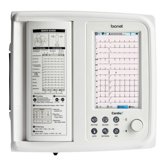
- Page 36 V 1.37 4-6) Front Panel Graphic Display Window Button Battery status Rotary key Power status During device boot up, you can see the system software version and the Bionet name. 2023. 09 36 / 183 Doc. # : BN_C7_OPM_307...
- Page 37 V 1.37 4-7) ECG Graphic display LCD The following descriptions explain data on the graphic LCD. ① ② ③ ④ ⑤ ⑥ ⑦ ⑧ ① ECG recording mode (10s, 1m, 3m, 5m, 10m) ② Heart rate ③ Patient ID. ④ Battery status or AC power connection status ⑤...
- Page 38 V 1.37 4-8) Spiro Graphic display LCD ① ② ③ ④ ⑤ ⑥ ⑧ ⑨ ⑦ ⑩ ① Patient ID ② Connection status of the external device ③ Battery status or AC power connection status ④ Forced Vital Capacity Test Menu ⑤...
- Page 39 V 1.37 4-9) Function Keys ① ② ③ ⑦ ④ ⑤ ⑥ ⑧ ⑨ ▣ Button Description RHYTHM. ① A real-time ECG waveform is continuously printed or prepared as a report. RECORD. ② 10sec. and long-term readings (1min., 3min., 5min., 10min.) are printed as an output form after processing.
- Page 40 V 1.37 ⑥ You can cancel the operation or switch to the previous mode by entering the main menu. ▣ Indicating Lights Battery charge indicator with AC connected: During operation, if the battery is fully charged, the LED lights green, otherwise it turns orange. AC Code connection indicator: The LED lights green when the ...
- Page 41 Note Bionet recommends replacing the lithium-ion battery after 24 months of use. Battery life depends on the frequency of use. Continued use by the battery power reduces the battery life and shortens the time of replacement.
- Page 42 Do not use a damaged battery on the equipment. Warning Pay attention to the polarity when replacing the battery. Bionet strongly recommends using the battery provided with the equipment. Using an unauthorized battery may damage the equipment. 2023. 09 42 / 183 Doc.
- Page 43 V 1.37 ▣ The Effect of Lithium-Ion Technology on the Battery Find out about lithium-ion battery technology here. The battery is discharged naturally even when not installed in the equipment. Discharging is caused by the current demanded by the lithium-ion battery integrated circuit. Battery is self- discharged due to the nature of lithium-ion cells, and the self-discharge rate doubles for every 10°C (18°F) rise in temperature.
-
Page 44: System Installation
- Install the equipment in a place with proper ambient temperature and humidity, and away from dust and flammable materials. 5-2) Connection Power Connect the power cable to the power supply and the power terminal on the back of the Cardio7 to power on. 5-3) Connecting Patient Cable Connect the Patient Cable to the patient cable connection port on the right side of the equipment. - Page 45 V 1.37 Warning Use only the ECG recording paper provided by Bionet for ECG recording. Otherwise, the poor printing quality may affect the doctor's diagnosis. Bionet is not liable for any problems caused by you not using the ECG recording paper provided by Bionet.
- Page 46 ⚫ Security of the network is the sole responsibility of the network operator. ⚫ Bionet recommends the following to guarantee the security of the network. ⚫ Define access authorization for the configuration of the host system so that no unauthorized alterations of the system can occur.
-
Page 47: System Start
V 1.37 6) System Start When you turn on the equipment, the product name is displayed and the initial menu appears as shown in the picture below. You can move to the main page of the chosen menu by touching the menu on the screen or rotating the key on the control panel. - Page 48 V 1.37 The picture below shows the ECG main screen that is loaded when you choose the ECG menu. The following is a description of the ECG initial screen menu. Menu Description ECG Recording mode (10s, 1m, 3m, 5m, 10m) Heart rate Patient information Barcode reader or USB Keyboard connection mark...
- Page 49 V 1.37 Power status (AC power or battery) To set up the size of the ECG waveform To set up the speed for printing out the ECG waveform Touch this button to set the System. Go to the main screen: Spiro, File, or Worklist. Go to the main screen: Spiro, File, or Worklist.
- Page 50 V 1.37 Go to the next page. Patient information Search data by entering search criteria. To print out the chosen data Delete the selected files. It appears when server is connected. Touch this button to set the System. Go to the main screen: ECG, Spiro, or Worklist. Touch [Worklist] to bring up the exam-requested patient management screen as follows.
- Page 51 V 1.37 Search data by entering search criteria. Go to the exam screen. Delete the selected files. It appears when server is connected. Touch this button to set the System. Go to the main screen: ECG, Spiro, or File. Touch (Study Queue icon) to bring up the Study Queue data management screen as follows.
- Page 52 V 1.37 Close the window. Note The icon appears on the right top corner only if there is an error while sending files. 2023. 09 52 / 183 Doc. # : BN_C7_OPM_307...
-
Page 53: Part I. Recording Ecg
V 1.37 Part I. Recording ECG Chapter 2. ECG Recording Preparation 1) Attaching the Electrodes To record a standard 12-lead ECG, attach electrodes to the patient’s body as shown below. The positions to attach limb electrodes are as follows: RL (N): Right leg LL (F): Left leg RA (R): Right arm LA (L): Left arm... -
Page 54: Connecting Electrodes
Connect the patient cable to the port on the right side of body and connect limb electrodes to the terminals of RL (N), LL (F), RA (R), and LA (L) of patient cable connected in the Cardio7 and chest electrodes to the terminals V1 (C1), V2 (C2), V3 (C3), V4 (C4), V5 (C5) and V6 (C6). -
Page 55: Recording Ecg
When conductivity between the skin and the electrodes is weak: Apply the ECG gel to the electrode-attaching spots and reattach the electrodes. If the ECG signal is not accurately acquired even after you try all the solutions above, the patient cable may be non-conforming. Contact Bionet's service center. 3) Recording ECG Enter accurate patient information. -
Page 56: Basic Setup
V 1.37 The following is a description of the ECG recording menu. RHYTHM. A real-time ECG waveform is continuously printed or prepared as a report. RECORD. 10 second long term readings (1 min, 3 min, 5 min, 10 min) are acquired and printed in output format. - Page 57 V 1.37 4-2) Changing the Configuration Value with The Rotary Key In this case, please follow these steps: enter Menu Mode, navigate and select Menu and then change values. - Entering Menu Mode The rotary key is supposed to rotate clockwise. When the user selects the ECG Main, the initial focus will point to the ‘patient’...
- Page 58 V 1.37 100mm/sec at the ‘Speed Setting’ POP-UP, the POP-UP window will disappear. 4-3) Using the touch screen to modify the information When using the touch screen, only two procedures, menu selecting and information modification, are required. - Selecting Menu Touch the menu buttons on the screen.
- Page 59 V 1.37 Patient ID Enter a unique number used in the hospital to classify patient medical data. Touch the input field of ID to display the keypad window consisting of alphabets and numbers. Use the keypad window to enter patient ID. When the user wants to set the data after inputting, the user can press OK button on the keyboard and if the user wants to cancel the setting, pressing ESC button will do it and the keypad window will disappear.
- Page 60 V 1.37 Enter an age and select the year of birth for >1 year old; enter age in the form of week or day for 1< year old. Automatic diagnosis is available from postnatal day 1 for pediatrics. Note Pediatric diagnosis of the ECG is available from the first day of birth. If age is not entered, an adult diagnosis is provided.
- Page 61 However, since the default setting of the entry method of each product may be different, check the method supported by Bionet before using them. Entry methods supported by Bionet products: International standard and USB ⚫ The products that have been tested by connecting to Bionet equipment are listed ⚫ below. Manufacturer...
- Page 62 V 1.37 4-6) Sensitivity Setup Adjust the Gain if the size of the output signal is too large to overlap neighboring channels, or it is too small to decipher. Settings: - Set the limb leads (I, II, III, aVR, aVL, aVF) and chest leads (V1, V2, V3, V4, V5, V6) to the same value: 2.5mm/mV, 5mm/mV, 10mm/mV, and 20mm/mV.
- Page 63 V 1.37 4-7) Printing speed Setup Adjust the width of the output signal for screen output and printout. The available values are 5mm/sec, 12.5 mm/sec, 25mm/sec, 50mm/sec, and 100mm/sec. 25mm/sec means that the ECG signal for 1 second is recorded with a length of 25mm. Note - If you set the Rhythm Size of monitoring to Report, the signal is always printed at 25mm/sec regardless of the Output Speed setting.
-
Page 64: Disclosure
V 1.37 5) Disclosure Touch the graph window of the ECG main screen for 3 seconds to switch to Disclosure screen. Disclosure is a function that stores ECG data in the equipment memory and shows it when executed. In the Disclosure screen: The pre-stored 5 minutes of ECG data are displayed in 1CH. The interval section of the pre-set mode (10 seconds) is marked with a square, allowing you to print diagnosis for the selected area or transmit data of the area. -
Page 65: Lcd Monitor Display
V 1.37 6) LCD Monitor display The current ECG signal is drawn on the LCD screen in real-time. Start the test after confirming that the signal is correctly transmitted from all leads. Note The detection range of heart rate is 30-300 bpm with ± 3bpm of error range. 7) Real-time Printing (RHYTHM Key) Press the [RHYTHM] key on the control panel to print the ECG signal in real-time. -
Page 66: Record Mode Printing
V 1.37 Note Do not attempt to attach or detach a USB device while the printer is working as it may cause the printer module to rattle. 8) Record Mode Printing Press the [RECORD] key to diagnose the ECG acquired during the set duration, and print the result. -
Page 67: Printing Form
V 1.37 Touch [OK] if the data is reliable. Note Set Preview settings in Setup→ ECG → Preview on. 9) Printing Form Record Form Set the diagnosis print format. Print Format Description 10-second resting ECG recording: I, II, and III in the first 2.5 seconds;... - Page 68 V 1.37 used for the 3CH+1 and 6CH+1 settings. By default, it is set to II, V1, and V5. As for 3CH+1, 6CH+1, and 6CH+1 (ST), II is used. All II, V1, and V5 are all used for 3CH+3. Beat Form Select between Text, Guide, Vector, and ST Map as additional print form after a diagnosis is printed.
- Page 69 V 1.37 Rhythm Form Set the real-time printout form. Print Format Description 3 leads are printed simultaneously. I, II, and III are printed first, and to change the printing lead, press the RHYTHM key on the control panel again. Each time you press the [RHYTHM] key, the sequence changes to I~III →...
- Page 70 V 1.37 Rhythm Report Form (3 CH) Rhythm Report Form (6 CH) 2023. 09 70 / 183 Doc. # : BN_C7_OPM_307...
- Page 71 V 1.37 Rhythm Report Form (12 CH) Record Report Form (3 CH + 1 RHY) 2023. 09 71 / 183 Doc. # : BN_C7_OPM_307...
- Page 72 V 1.37 Record Report Form (3 CH + 3 RHY) Record Report Form (6 CH + 1 RHY) 2023. 09 72 / 183 Doc. # : BN_C7_OPM_307...
- Page 73 V 1.37 Record Report Form (12 CH) Record Report Form (6 CH + 1 RHY (ST Map)) 2023. 09 73 / 183 Doc. # : BN_C7_OPM_307...
- Page 74 V 1.37 Record Report Form (1 CH +3) Record Report Form (Cabrera Report) 2023. 09 74 / 183 Doc. # : BN_C7_OPM_307...
- Page 75 V 1.37 Record Report Form (BEAT REPORT - TEXT) Record Report Form (BEAT REPORT - VECTOR) 2023. 09 75 / 183 Doc. # : BN_C7_OPM_307...
- Page 76 V 1.37 Record Report Form (BEAT REPORT - GUIDE) Record Report Form (BEAT REPORT –ST Map (Dot)) 2023. 09 76 / 183 Doc. # : BN_C7_OPM_307...
- Page 77 V 1.37 Record Report Form (BEAT REPORT –ST Map (Bar)) 2023. 09 77 / 183 Doc. # : BN_C7_OPM_307...
- Page 78 V 1.37 9-1) Explanation of BEAT REPORT Variables PR: PR Interval PA: Amplitude of P Wave (P Amplitude) PD: Duration of P Wave (P Duration) QA: Amplitude of Q Wave (Q Amplitude) QD: Duration of Q Wave (Q Duration) RA: Amplitude of R Wave (R Amplitude) RD: Duration of R Wave (R Duration) SA: Amplitude of S Wave (S Amplitude) SD: Duration of S Wave (S Duration)
- Page 79 V 1.37 Note The unit of parameter intervals (duration, interval) used in the Beat Report is , and the unit of height (amplitude) is Note Dextrocardia Normally, the heart is located in the left chest. However, there are cases where the heart is located in the right chest, which is called Dextrocardia.
-
Page 80: Printing Diagnostic Copy (Copy Key)
V 1.37 10) Printing Diagnostic Copy (COPY key) You can reprint the saved data with the same settings as before, or print it by changing its settings of Filter, Gain, Output Speed, Channel Configuration, Rhythm, etc. When the diagnosis is issued, press the [COPY] key on the control panel to print a report with the changed settings applied to the saved data. -
Page 81: System Setup
V 1.37 11) System Setup Choose the 'Setup' button on the initial ECG main screen to change preferences. Setup menu consists of Basic Setup, Network Setup, Hospital Setup, ECG Setup, Record Setup and Service Setup and you can change the setting at each window. The main page shows Basic Setup. - Page 82 V 1.37 11-1) Basic Setup When choosing Basic menu at the left side of the Setup page, you will see the page for Basic Setup. Basic Setup consists of Date, Time, Touch screen, Start Option, Unit, Date Type and Device Name menus.
- Page 83 V 1.37 11-1-2) Touch Setup This is a menu to set up the coordinates of the touchpad. When selecting the 'Touch' menu at the Basic Setup page, setup page will disappear and the coordinates for setting calibration will appear as shown below. Follow the instructions shown on the screen, and then the coordinates will be set up.
- Page 84 V 1.37 11-1-3) Language when selecting 'Language menu at the Basic Setup page, you can choose the language among English, French, German, Italian, Korean, Polish, Portuguese, Rumanian, Russian, Spanish and Turkish. Select the language you want to use and click the OK button and then you can use the service in the chosen language.
- Page 85 V 1.37 PC; therefore, it cannot be revised by user. 11-2) Network Setup When connecting the equipment with LAN to interface with the outside PC, network setup is needed. Network IP is required, and DNS is not used. When selecting the Network menu at the left side of the System Setup page, Network Setup page will show up at the right side.
- Page 86 V 1.37 Note To connect to the PACS server, you must enter the Device IP manually. If the IP is set to DHCP, the device IP may change every time the device is turned on. If the changed IP is different from the device IP registered in the PACS server, server connection may not be made.
- Page 87 11-2-2) PACS Server Setting When selecting the PACS Server, the additional information should be set through the Settings Menu. The screen for related settings such as the AE Title, IP and Port of Cardio7, Worklist Server and Store Server will appear. 2023. 09 87 / 183 Doc.
- Page 88 V 1.37 When the input window of each item is selected, the keyboard window will appear: Enter the applicable contents. When entry is completed, click the “Verify” button so that the connection between the Worklist Server and the Store Server can be confirmed. When successful, the “Verify: Success”...
- Page 89 V 1.37 Tomorrow”, “One Week” and "A Week ago". For today (today-today), both the start and end dates are set to today, and for today (today- blank), only the start date is set to today to get the worklist. Auto Update Worklist If you tick the Auto Update Worklist, the Worklist update will be run automatically whenever you enter the Worklist screen.
- Page 90 It shows the menu screen for related settings such as Work type, GDT Directory, Component name, File name, and Image type. Work Type Set the GDT operation of the equipment. - Server: Cardio7 receives requests and commands. - Client: Cardio7 sends requests and commands. 2023. 09 90 / 183...
- Page 91 Enter the type of format in which the shared folder information and date information to be used by the GDT protocol. Component For use GDT protocol, enter the EMR name and abbreviation and the name of Cardio7 and abbreviation. Short Name Select the name type of the file to be shared by the GDT protocol.
- Page 92 The message “Verify: Success” is displayed on success, and the message “Verify: Fail” on failure. 11-2-5) Wireless Network Setting (1) Connect the USB to the USB port of Cardio7, and check whether or not the wireless icon 2023. 09 92 / 183...
- Page 93 V 1.37 ) appears in the Status bar on the top of the screen. (2) Navigate to System Setup -> Network, and Set the Device as “Wireless”. When selection is done properly, the "Survey" button on the bottom will be activated. (3) Select the [Search] button to search for the AP.
- Page 94 V 1.37 If you want to connect to Hidden Wi-Fi, click the [Add] button and manually enter the network name before proceeding. Note Search for an AP and set up a security key to use a wireless network. If the AP to connect to does not require authentication, you are automatically connected with no need to enter the security key.
- Page 95 V 1.37 (6) Upon the completion of input, click the [OK] button; Connection will be attempted and the message describing the connection status will appear. (7) When the message reporting a proper connection appears, click the [Close] button. When connection is successful, the wireless icon on the status bar at the bottom of the screen will be changed into (8) If connection fails, connection can be re-attempted by pressing the [Retry] button.
- Page 96 Refer to the Network Setup part of the User Manual for more details. Note Bionet recommends using English alphabet to name the wireless network (SSID) of the AP. Inputs in Korean or other languages can be shown broken or as strange characters.
- Page 97 V 1.37 11-4) ECG Setup When selecting the ‘ECG’ menu at the left side of the Setup page, ECG Setup page will show up at the right side. 11-4-1) Printing channel setting [Print Setup] Monitoring Form (Mon Form) Set up real time-printout form. Click ‘Mon Form,’ and then a POP-UP window for channel list will be displayed.
- Page 98 V 1.37 change the channel, press ‘RHYTHM’ on the control panel. - 12CH printing: To print 12channels at the same time (I ~ V6) Note To change the printing lead with the RHYTHM key in 3CH and 6CH settings, the Rhythm Size must be set to Continue.
- Page 99 V 1.37 Paper Size You can set up the paper size. When you click the ‘Paper Size’ menu, ‘A4’ will be selected and when clicking it again, ‘Letter’ will be selected. Default is set as ‘Report’. - ‘A4’: to output at 297mm for Report Size printout. - 'Letter': to output at 279 mm for Letter Size printout.
- Page 100 V 1.37 collection with [RECORD], [AUTO] and [NET] keys. While “Preview” screen is showing, the user can perform print, save or transmit the data after clicking [OK], or no action after selecting [Cancel] - The first page: ECG 0 - 6 seconds signal data, ID, Name, and Diagnosis - The next page: ECG 6 - 10 seconds signal data, ID, Name, Filter setup, Rhythm parameter values Note...
- Page 101 V 1.37 11-4-3) Quick Print Set the Quick Print options. Since the data pre-saved for a set amount of time (0-10 seconds) is used, it takes less time to acquire data, reducing time to providing data. Note With the Quick Print option set, touch the ON button when the signal stabilizes. Since the data pre-saved for a set amount of time is used, diagnosis and printing may be affected unless the saved data is stabilized.
- Page 102 V 1.37 There are three types of an AC power noise filter: 60Hz, 50Hz and OFF. When set to OFF, the filter will not be applied. If the filter is set to 50Hz or 60Hz, then the AC filter will remove 50Hz or 60Hz power noise correspondingly.
- Page 103 V 1.37 Note If ‘RA’ Lead becomes Fault, the wave types of all Leads will not be indicated. If ‘LA’ Lead becomes Fault, the wave types of I and V1-V6 Leads will not be indicated. If ‘RA’ Lead becomes Fault, Lead Fault message might not be shown, and the wave types of all Leads might be indicated.
- Page 104 V 1.37 You can select ON or OFF by clicking the ‘Pacemaker’ item. When it is on, the location of the pacemaker will be printed out, while when it is off, it will not be printed out. Note - It is recommended to set the pacemaker off for normal use and only when the patient uses a pacemaker, set it on.
- Page 105 V 1.37 11-4-8) Method of Leads Place ‘Leads Place’ menu shows how to connect electrodes on the graphic display. Focusing on and selecting ‘Leads Place’ menu will bring the screen shown below. At that time, enter the screen- touch, rotary or [ESC] key; and then the ‘how to connect electrodes’ screen will disappear while going back to the ‘ECG Setup’...
- Page 106 V 1.37 11-4-9) Demo Mode Setting This menu puts Cardio7 in demo mode. When it is set to ON, 60bpm Sinus Normal Rhythm signal will be displayed on the device and [DEMO] sign will appear on the upper part of the LCD screen.
- Page 107 V 1.37 11-5-1) ‘AUTO’ key setting When the ‘Store’ menu has the focus, click it to set up ‘Yes’ or ‘No’. When ‘Yes’ is selected, you can operate the ECG test by pressing the [AUTO] key on the control panel and the ECG data will be automatically saved, but when ‘No’ is selected, the ECG data will not be saved.
- Page 108 V 1.37 ST Level setting Set the ST Segment diagnosis during automatic diagnosis on 10-second recording. AUTO: The J Point related to ST Level is automatically set. 60msec: J Point is set to 60msec point. 80msec: The J Point is set to the 80msec point. V Channel setting ‘V Change’...
- Page 109 Caution When the patient, who had an operation to have a heart assist device, uses Cardio7, it should be done under the supervision of a health care professional. 11-6) Service Setup If ‘Service’ menu on the left of the Setup screen is selected, the other Setup screen related to ‘User Security Set’...
- Page 110 V 1.37 At ‘Manufacture Set’ setup, it is possible to change Upgrade and Device Options: please contact the Bionet Service Center. 11-6-1) Factory (Reset Settings) In order to reset to factory conditions, press the [Factory] button and enter the Password.
- Page 111 V 1.37 Net Device Wired Configure Manually Device IP 192.168.30.224 Subnet Mask 255.255.255.0 Gate way 192.168.30.1 BMS Server 0.0.0.0 Hospital blank Doctor blank Preview Quick Print Lead Fault Pacemaker QRS sound Demo Mon Form 12ch Mon Size Continue Grid Rec Form 3ch + 3 Paper Size Report...
- Page 112 User Password can be configured. User Password is the number entered for Factory and Data Erase. The password should be a 4-digit number. Note Contact the Bionet service center when you forget your password. 2023. 09 112 / 183 Doc. # : BN_C7_OPM_307...
-
Page 113: Part Ii. Using Spirometer
V 1.37 Part II. Using Spirometer Chapter 3. How to Install 1) Connecting Spirometer Handle Spirometer handle should be connected to the main body by plugging in the end of its cable to USB port in the main body (shown below) <Rear View>... - Page 114 V 1.37 (1) Press the Front Cover Lock Switch on the top left corner of spirometer handle and open the Front Cover in semi-circle shape. 2) Put the mouthpiece on the inserting lot made on the open side. (3) Press the Front Cover with a little force to close Caution A mouthpiece is for single use only.
-
Page 115: Chapter 4. How To Use
V 1.37 Chapter 4. How to Use 1) Getting Started Turn on the switch on the main body and locate the selection box in the Spirometer area by turning the rotary key on the initial screen. Afterward, press the rotary key or touch the selection box in the Spirometer area to shift to Spirometer measurement mode. -
Page 116: Entry Of Patient Information
V 1.37 2) Entry of Patient Information The personal information of the patient must be entered before the pulmonary function test begins. Specifically, items such as “Age”, “Gender”, “Height” and “Race”, which are indicated as “*” in their input fields, must be entered because they are essential for the diagnosis of the pulmonary function. - Page 117 V 1.37 〈Patient Information Selection Mode〉 To activate the Information Input mode, locate the shaded block in the desired “Patient Information” area and press the rotary key. The information can be entered by using the rotary key or touching the desired area. The Entry Mode consists of the Keyboard mode, which enables the input of both characters and numbers, and the Keypad mode, which enables the input of numbers only.
- Page 118 V 1.37 Note When entering an ID, it is impossible to enter special characters such as “, <, >, ?, /, *, |, :, \, etc. (these invalid characters are set to be inactive) When entering an ID, an English keyboard will be displayed, regardless of whether there is a multi-language set-up.
- Page 119 V 1.37 2-4) Entering Gender Touch the input field of Gender to select Male or Female. 2-5) Entering Height Enter the patient height in the same way as entering the age. inches If the Height Unit is set to inches in System General Setup, enter the height in 2-6) Entering Weight Enter the patient weight in the same way as entering the age.
-
Page 120: Forced Vital Capacity (Fvc) Test
V 1.37 3) Forced Vital Capacity (FVC) Test 3-1) FVC Test (Base Test) Select [FVC] by turning the rotary key or touch.At this time, the patient information must be entered beforehand to ensure diagnosis based on the measured results. When you select the [FVC] menu, the screen shifts to the FVC Test screen following the test preparation process as shown in the figure below. - Page 121 V 1.37 A message appears as shown below if the Spirometer handle is not connected or power is turned off on the handle. This message is also displayed in the same way during the SVC Test and MVV Test. At this time, touch [Exit] by hand or press it using the rotary key to go to the main menu and check the handle before resuming the test.
- Page 122 V 1.37 The screen below appears, and FVC test measurement is ready if the Spirometer handle is connected normally. 2023. 09 122 / 183 Doc. # : BN_C7_OPM_307...
- Page 123 V 1.37 Have the patient hold the spiro handle and place it in front of his or her mouth, and touch [Start]. To ensure accuracy, measurement must be carried out exactly according to the procedure described below. < How to Breathe during FVC Test > 1) Breathe twice or more as usual.
- Page 124 V 1.37 Note - In principle, the patient should be in standing position. The test can be done in a sitting position as well, but the more effortful lung capacity are acquired in standing position. Pregnant women, obese people and pediatric can sit down to take the test. - Raise your chin upwards by about 15 degrees and keep it all the way: avoid bending your neck or chin.
- Page 125 V 1.37 important, since the graph drawn during the measurement just indicates the fact that the patient is breathing, and dose not correspond with actual breathing data. 3-2) Result screen Press [Stop] button by using rotary key or touchscreen to signal the machine that measurement is finished.
- Page 126 V 1.37 ● Print : Print out the test result. - It prints the measurement result in a graph and a chart. Note Do not attempt to attach or detach a USB device while the printer is working as it may cause the printer module to rattle.
- Page 127 V 1.37 ● Select BEST measurement - At the end of the measurement, it shows the BEST measurement number selected in the automatic diagnosis. The selection criteria for Best measurement are obtained at the maximum value of the FVC+FEV1. If it needs to change the automatically selected Best measurement, it can select a different measurement number with a touch.
- Page 128 V 1.37 ◆ If “Yes” is selected (1) A message appears, requiring the entry of Patient ID; if the Patient ID was not entered before saving the data, the Patient Information Entry window would be displayed. (2) The data-saving process starts if Patient ID is entered (3) Once the saving process is complete, a message box asking whether the patient information is to be deleted appears.
- Page 129 V 1.37 Note The following messages will appear when the memory is full. Message appeared after saving the last data ➢ Message appeared when selecting to save data again after saving all data ➢ 2023. 09 129 / 183 Doc. # : BN_C7_OPM_307...
- Page 130 V 1.37 - FVC Test Pint Form Note If a USB device is installed or detached during printout, the printer module may rattle, so please refrain from removing and installing it during printout. 2023. 09 130 / 183 Doc. # : BN_C7_OPM_307...
- Page 131 V 1.37 3-3) FVC+(PRE-POST Bronchodilator Comparison) Test (1) “FVC+” enables the comparison of the results of the test performed twice before and after medicine is administered. The procedure is as follows: First, conduct the measurement according to the FVC test method, and then save the data. (2) Once the data is saved, go to the Data List menu to check the data indicated as “FVC”...
- Page 132 V 1.37 (5) The test can be conducted in the same way as FVC by selecting “FVC+” menu. (6)The parameters and graphs of pre-administration (Base) and post-administration (Post) can be compared if the results of measurement are printed. (7)You can see “FVC+” displayed on the data list menu if you press the “Exit” button and save the data.
- Page 133 V 1.37 - FVC+ Test Print Form 2023. 09 133 / 183 Doc. # : BN_C7_OPM_307...
-
Page 134: Slow Vital Capacity (Svc) Test
V 1.37 4) Slow Vital Capacity (SVC) Test Touch [SVC] in the Spiro main screen to start SVC testing. Have the patient hold the spiro handle and place it in front of his or her mouth, and touch [Start]. When the equipment sounds a beep, have the patient bite the mouthpiece and start the test. Follow the procedure below to achieve accurate test result. - Page 135 V 1.37 < How to Breathe during SVC Test > 1) Breathe as usual for at least four times You will hear a click if breathing is detected as usual for more than four times. 3) Exhale slowly as much as possible (RV level). 3) Inhale slowly as much as possible (TLC level).
- Page 136 V 1.37 Speed in the positive side(F[L/s]) of the screen indicates exhalation and that in the negative side inhalation. If you press [ESC] key while you are taking measurement, the machine would stop taking the measurement, and return to spirometer initial menu screen. Once the measurement is finished, a graph(V-T) showing change in volume of lungs to passage of time is drawn like the screen shown below.
- Page 137 V 1.37 The best choice of SVC for automatic diagnosis is determined by the maximum value of SVC. The 'Best', 'New', 'Print' and 'Exit' menus are used the same way as for FVC test measurements. 2023. 09 137 / 183 Doc.
- Page 138 V 1.37 - SVC Test Print Form 2023. 09 138 / 183 Doc. # : BN_C7_OPM_307...
-
Page 139: Mvv(Maximum Voluntary Ventilation) Test
V 1.37 MVV(Maximum Voluntary Ventilation) Test Touch [MVV] in the Spiro main screen to start MVV testing. Touch [Start] in the screen shown below to start a test. 2023. 09 139 / 183 Doc. # : BN_C7_OPM_307... - Page 140 V 1.37 Have the patient hold the spiro handle and place it in front of his or her mouth, and touch [Start]. When the equipment sounds a beep, have the patient bite the mouthpiece and start the test. Follow the procedure below to achieve accurate test result. <...
- Page 141 V 1.37 When the set time (TMVV) - 12 seconds - passes, the test ends and the result is displayed on the screen. MVV, respiratory cycle (FB), and total respiratory capacity (TV) are calculated and displayed at the top of the screen. Touch [Stop] to finish during the test. You are moved to the initial MVV test screen.
-
Page 142: Calibration
V 1.37 - MVV Test Print Form 6) Calibration 2023. 09 142 / 183 Doc. # : BN_C7_OPM_307... - Page 143 V 1.37 Select [CAL] from the sub-menu and press the Rotary key, or tab to the ’CAL’ field to see the Calibration Main menu screen as below. Calibration should be conducted in the following order: Violation of order might cause error in measurement.
- Page 144 V 1.37 6-1) Calibration When you are ready, touch [Start] to start calibration. The screen below appears if the syringe handle is moved back and forth. To ensure accurate correction, move the handle only after a beeping sound is heard. A graph representing Flow and Volume is drawn according to the movement of the syringe.
- Page 145 Touch [Exit] to finish Calibration and return to the top menu. Note Bionet recommends quarterly calibration of spirometer measuring device. Be sure to perform calibration when changes in temperature and air pressure are significant. Repeat the calibration until the calibration result falls within ±3%.
- Page 146 V 1.37 - Calibration Print Form 2023. 09 146 / 183 Doc. # : BN_C7_OPM_307...
-
Page 147: System Setup
V 1.37 7) System Setup System Setup menu is used to set up device-related details. From the initial screen of Spirometer, select ‘SETUP’ by using Rotary switch or tab. System Setup menu consists of Basic Setup, Network Setup, Hospital Setup, Spiro Setup, Calibration Setup and Service Setup and you can change the setting at each window. - Page 148 V 1.37 7-4-1) Formula The ‘Formula’ is the diagnosis standard when executing a FVC test, therefore, after selecting the ‘Formula’, it is required to select one menu among ‘Morris’, ‘Knudson’, ‘ECCS’, ‘Korea CJK’ or ‘Pereira’. In addition, the contents of each Formula are explained as the below. Main Use Area Formula Description...
- Page 149 - Please select the patient of the FVC data in the File for the Post inspection and execute the ‘Main’→ ‘Spiro’ menu. 7-4-5) Spirometer handle type Set type of the Spirometer handle (USB or Serial). Cardio7 only connects to this type of Spirometer handle. 7-4-6) Condition Setting “Condition”...
- Page 150 V 1.37 7-5) Calibration Setup When selecting the ‘CALIB’ menu at the left side of the Setup page, Calibration Setup page will show up at the right side. When selecting items such as Pressure, Humidity, Temperature and Syringe Size by using Rotary switch or tabbing, the number keypad input window will appear.
-
Page 151: Part Iii. Data & System Management
V 1.37 Part III. Data & System Management Chapter 5. File management 1) Display and function ⓛ ② ③ ④ ⑤ ⑥ ⑦ ⑧ ⑨ ⑩ ① Page information For example, [1/20] means that you see the first page among total 20 pages. 1 Page contains 24 lines of Data. -
Page 152: Data Printing
V 1.37 ③ Button to skip to the next page ④ Button to check the patient’s information of the chosen data saved ⑤ Button to search the data you want ⑥ State of battery or AC power connection ⑦ Button to print out the chosen saved data ⑧... -
Page 153: Data Deleting
V 1.37 Note You should avoid attaching and detaching a USB device while printing out, as it could cause the printer module to rattle. 3) Data deleting When pressing the ‘Delete’ button, a small pop-up menu will show up. You can choose to press the ‘select’... -
Page 154: System Setup
V 1.37 4) System Setup When clicking the ‘Setup’ button at the ECG data file management page, you will see a ‘System Setup’ window as shown below. See "Chapter 2. 11) Setup". 4-1) Basic Setup ‘PAT Info.’ menu is to set up whether the patient information is retained or not, when you move the main screen of the Spiro/ECG. - Page 155 V 1.37 4-2) File Setup When clicking the ‘FILE’ button, you will see ‘FILE’ window as shown below. You can activate the automatic deletion function by clicking the ‘Auto Del.’ menu in the ‘FILE’ menu window. When the automatic deletion function is activated, when a new file is saved beyond the maximum storage capacity, the oldest file is deleted and then saved.
-
Page 156: Switching Menu
V 1.37 when selecting one of BMS Server or USB. - BMS Server/PACS Server : To save the data in the BMS Server or PACS Server. - USB: To save the data in the external USB Memory When clicking the ‘Method’ button, a small line window will show up and it will disappear when selecting Manual, Select, All or All New. -
Page 157: Patient Information
V 1.37 The patient’s information of selected data does not transmit when skipping to ‘Worklist Management’ screen. But it depends on the setting value of ‘PAT Info.’ menu when skipping to ‘ECG’ main screen. - ECG: Skip to ECG main screen - Worklist: Skip to ‘Worklist Management’... -
Page 158: Data Transfer
V 1.37 When the search takes a long time, a message will show up to let you know the progress. After searching, you will see a data search result page. 8) Data transfer You can transfer the saved data to the external device at the Spiro/ECG data file management page by using the ‘NETWORK’... - Page 159 V 1.37 If you transfer all of the data, a message with progress speed or other information will be shown as below. In this case, the total number of files and the file being transferred currently will be displayed. Note When transmitting multiple sets of data to PC after saving, a network error could occur which may cause transmission halt and subsequent loss of data.
-
Page 160: Data Import
If 2 different USB memory devices are connected, a system message window prompting you to select one of them will appear. If the external device is not connected to Cardio7, the error message will be shown as below. 2023. 09 160 / 183 Doc. - Page 161 V 1.37 If you select the ‘Selected’ menu in the ‘Import File List’ screen, after receiving the selected data from the external device a system message will be shown as below. If you select the ‘All’ menu in the ‘Import File List’ screen, a system message with pro gress speed will be shown as below.
-
Page 162: Chapter 6. Worklist Management
V 1.37 Chapter 6. Worklist management 1) Display and function ⓛ ② ③ ④ ⑤ ⑥ ⑦ ⑧ ⑨ ⑩ ① Current page/total number of file pages For example, [1/20] means that you see the first page among total 20 pages. 1 Page contains 24 Data. -
Page 163: Spiro/Ecg Test
V 1.37 ③ Go to the next page. ④ Patient information ⑤ Worklist Search ⑥ Battery status or AC power connection status ⑦ Connection status of the external device. ⑧ Deleting a User button (After interlocking with the PACS Server, press the ‘Update’ button) ⑨... -
Page 164: Data Deleting
V 1.37 Caution Each functional key action of Spiro / ECG Main Menu is as follows: - RECORD: not saving measured data but performing output only. - NET: not saving measured data but transferring it to a PC. - AUTO: running according to Auto Key setup of system. To save measured data for the Test requested, configure Spiro / ECG Store on Auto Key setup as Yes, and then start measurement by pressing the Auto button. -
Page 165: System Setup
V 1.37 4) System Setup When clicking the ‘Setup’ button at the Spiro / ECG data worklist management page, you will see the ‘worklist System Setup’ window as shown below. Note The steps for Network, Hospital and Service Setting are identical with the steps for Spiro/ECG Main setting. -
Page 166: Patient Information
V 1.37 6) Patient information When selecting saved data at the ECG file management page by using rotary key or touch screen, the focus will appear at the data list. Press the ‘Info’ button to see the ‘Patient Information’ page. After checking all the information, press the OK button and then the ‘Patient Information’... -
Page 167: Data Search
V 1.37 7) Data search When clicking the ‘Search’ button at the Spiro/ECG data order management page, you will see a ‘Patient Search’ window as shown below. If you rotate the rotary key, the ‘search condition’ button will have focus. Press the [Find] button after inputting the information about ID, Name, Date or Age. -
Page 168: Chapter 7. System Management
Chapter 7. System Management 1) Maintenance and Cleanliness Keep Cardio7 equipment and handles clean. Avoid damaging or contaminating the equipment using the methods recommended below. If you use the substances - including not allowed substances - that can damage on the product, warranty is not applied even during the warranty period. -
Page 169: Regular Check-Up
Service Center, or the store where you purchased the product. 2) Regular Check-up Like every other medical product, Cardio7 requires a regular check-up once a year. Please refer to the Service manual for the information on the check-up. 3) Trouble Shooting Printing was not successful: ⚫... - Page 170 Connect the external USB keyboard to the USB port before you turn on the power of Cardio7. If you connect the external USB keyboard to the USB port after you turn on the power of Cardio7, you should turn off the power of Cardio7 and turn on again.
- Page 171 V 1.37 Enter password When wrong number of length error. Please check and input valid and characters be entered as Please re-enter correct password password your password The internal memory is full. Please erase When over 200 files are Erase files in File menu other files or stored at internal memory transfer to...
- Page 172 V 1.37 Please contact ‘Network Team’ to The devices IP address is IP address check IP address, and set right IP already in use on the conflict. in turn of System setup and network Network Connection Error. Please check LAN cable Check Lan cable, When there is failure of connection, network setting,...
- Page 173 V 1.37 When the battery level is Please connect power cable or Recharge Battery! charge battery Printer stops working due Printer: Time out. to technical problem of React the printer device Printer: Busy When the wrong printer React the printer continue data were input When the Printer gets...
- Page 174 V 1.37 Correction factor(s) When the factor value is out Repeat the calibration until the outside of tolerance range during calibrated values are within the of acceptable the calibration tolerance range range of 0.8~1.2 Please repeat the calibration until the When the difference values Repeat the calibration until the calibrated value...
- Page 175 Guidance and manufacturer’s declaration – electromagnetic emissions The Cardio7 is intended for use in the electromagnetic environment specified below. The customer or the user of the Cardio7 should assure that it is used in such an environment. Emissions test Compliance...
- Page 176 Guidance and manufacturer’s declaration – electromagnetic immunity The Cardio7 is intended for use in the electromagnetic environment specified below. The customer or the user of the Cardio7 should assure that it is used in such an environment. IEC 60601 Electromagnetic...
- Page 177 0 % U ; 250/300 cycles supply or a battery be cycles IEC 61000-4-11* used with the system power source. Cardio7 is suitable to use in professional healthcare environment. Radiated fields 65 A/m Max 65 A/m Max Portable radio frequency in close 30 kHz - 13.56 MHz...
- Page 178 V 1.37 Chapter 8) Specification ECG Leads Simultaneous 12 Leads Resting ECG Recording Channel 3CH+1RHY, 3CH+3RHY, 6CH+1RHY, 12CH, 6CH+ST map, 1CH+3, Cabrera Report 1CH Long Time (1min, 3min, 5min,10min) and Special Beat Report (Text, Guide, Vector, ST map) Gain 2.5, 5, 10, 20, Auto (I~aVF: 10, V1~V6: 5) mm/mV Printing Speed 5, 12.5, 25, 50, 100 mm/sec Sampling Rate...
- Page 179 V 1.37 Spiro FVC: FVC, FEV1, FEV1/FVC, FEF 0.2-1.2L, FEF 25-75%, FEF 75-85%, PEF, FEF 25%, FEF 50%, FEF 75%, FIVC, FEV6, PEFT, FET 100%, Error Code, Extrapolation volume Measuring values SVC: SVC, TV, ERV, IRV, EC MVV: MVV, FB, TV Flow Volume loop Presentation Volume Time Graph...
- Page 180 V 1.37 Battery type Replaceable and Rechargeable, Lithium ion, 10.8V, 3250mA Battery Capacity 6 hours of normal use or print 200 ECG pages (12 channel format at 25mm/s and 10mm/mV) The battery will charge to its full capacity within 3 hours with the power off.
- Page 181 For the electrode, use the same product as provided or a product with biocompatibility certified by international standards. Caution Cardio7 should be used in the presence of a health care professional when used for patients who have undergone Cardiac Assist Device surgery. 2023. 09 181 / 183 Doc.
- Page 182 Telephone: Seller Name Manufacturer Name ※ Thank you for purchasing Cardio7. ※ This product is a medical device. ※ This product has passed thorough quality control and strict inspection. ※ Compensation criteria for repair, exchange, and refund of this product are in accordance with the Fair Trade Commission Notice "Consumer Damage Compensation Regulations."...
- Page 183 Bionet Co., Ltd Model Name: Cardio7 Copyright © 2023 Bionet CO., LTD. All Rights Reserved.
Need help?
Do you have a question about the Cardio7 and is the answer not in the manual?
Questions and answers