Table of Contents
Advertisement
Advertisement
Table of Contents

Related Manuals for Bionet FC1400


Summary of Contents for Bionet FC1400
- Page 1 FC1400 Operation Manual Ver. 2.04 2017.01.20 www.ebionet.com...
- Page 2 “Consumer’s protection law” noticed by Economic Planning Dept. Warranty period is 1 year (Two years in Europe). We will repair or replace any part of the FC1400 found to be defective in usual operating circumstance for free to you.
- Page 3 • E-mail: Sales@ebionet.com Service@ebionet.com • URL: http://www.ebionet.com ※ In the event of a malfunction or failure, contact Service Dept. Of Bionet Co., Ltd. along with the model name, serial number, date of purchase and explanation of failure. FC1400OM-2.04 3 / 95...
- Page 4 - When a problem has been caused by repair performed by persons other than an engineer from Bionet Co., Ltd. or from any agency authorized by Bionet Co., Ltd. 3. Other cases - When a problem has been caused by a natural disaster (fire, damage by salt, damage by water, earthquake, etc.)
-
Page 5: Table Of Contents
FC1400 Operation Manual FC1400 User Manual Table of Contents CHAPTER 1. BASICS ....................8 ......8 EFINITION OF ARNING ROHIBITION ANDATORY CTION ................9 ENERAL RECAUTION ON NVIRONMENT ..............13 ENERAL RECAUTION ON LECTRIC AFETY .......................18 AFETY YMBOLS CHAPTER 2. INSTALLATION ................. 19 1) O ...................19... - Page 6 FC1400 Operation Manual FC1400 User Manual CHAPTER 9. CLINICAL MARK AND NOTE ............50 CHAPTER 10. TRACE ..................... 52 1) T ........................52 RACE AREA 2) T ..........................53 RACE 3) S ....................54 ETTING UP TRACE MODES CHAPTER 11. PRINT ....................56 1) P ....................56...
- Page 7 FC1400 Operation Manual FC1400 User Manual CHAPTER 15. NST ....................70 1) NST .......................70 MEASUREMENT 2) NST S .........................70 ETTING CHAPTER 16. CTG TERMS ..................71 1) S .........................71 ETTING 2) CTG O .........................71 UTPUT 3) CTG M ..................72 EASUREMENT RESULTS...
-
Page 8: Chapter 1. Basics
FC1400 Operation Manual FC1400 User Manual Chapter 1. Basics Definition of Warning, Prohibition, Mandatory Action, and, Note For special emphasis on agreement, terms are defined as listed below in user’s manual. Users should operate the equipment according to all the warnings and cautions. -
Page 9: General Precaution On Environment
FC1400 Operation Manual FC1400 User Manual General Precaution on Environment Do not keep or operate the equipment in the environment listed below Avoid placing in an area exposed to moisture. Avoid exposure to direct Do not touch the equipment sunlight with wet hands. - Page 10 FC1400 Operation Manual FC1400 User Manual CAUTIONS Before Installation Compatibility is critical to safe and effective use of this device. Please contact your local sales or service representative prior to installation to verify equipment compatibility. Defibrillator Precaution Patient signal inputs labeled with the CF and BF symbols with paddles are protected against damage resulting from defibrillation voltages.
- Page 11 Negligence BIONET does not assume responsibility for damage to the equipment caused by improperly vented cabinets, improper or faulty power, or insufficient wall strength to support equipment mounted on such walls.
- Page 12 FC1400 Operation Manual FC1400 User Manual NOTES Power Requirements Before connecting the device to the power line, check the voltage and frequency. Ratings of the power line are the same as those indicated on the unit’s label. If this is not the case, do not connect the system to the power line until you adjust the unit to match the power source.
-
Page 13: General Precaution On Electric Safety
The equipment should not be placed in the vicinity of electric generator, X-ray, broadcasting apparatus to eliminate electric noise during operation. Otherwise, it may cause incorrect results. Isolated power line is important for FC1400 To use same power source with other electric instruments may cause incorrect results. - Page 14 FC1400 Operation Manual FC1400 User Manual NOTE This equipment must only be connected to a supply mains with protective ground. NOTE Avoid contact with the connector pin of the equipment and the patient at the same time while the equipment is in use.
- Page 15 Maintenance and Washing Equipment Connection Although FC1400 and its accessories can be cleaned in many ways, please use the methods recommended below to avoid unnecessary damage to or contamination of the equipment. If any dangerous material other than those designated for cleaning has been used, the resulting contaminated or damaged equipment will not be repaired free of charge even during the warranty period.
- Page 16 FC1400 Operation Manual FC1400 User Manual Electric cables and lead wires can be wiped off or cleaned with towels wet with lukewarm water, neutral soap, or isopropyl alcohol. Using ethylene oxide for intensive disinfection (almost complete sterilization) is allowed. Note, however, that it will reduce the lifetime of cables or lead wires. Clean the belt using soap and water while making sure that the water temperature does not exceed 60°C.
- Page 17 FC1400 Operation Manual FC1400 User Manual NOTE Annual Servicing – For continued safety and performance of the monitor, it is recommended that the calibration, accuracy, and electrical safety of the monitor be verified on an annual basis by a Bionet Service Representative.
-
Page 18: Safety Symbols
FC1400 Operation Manual FC1400 User Manual Safety Symbols The International Electro technical Commission (IEC) has established a set of symbols for medical electronic equipment which classify a connection or warn of any potential hazards. The classifications and symbols are shown below. -
Page 19: Chapter 2. Installation
From the signals returned after being reflected by the heart of the fetus, FC1400 extracts Doppler frequencies that vary with the movements of the heart of the fetus to output changes in the heartbeats of the fetus as sounds for the analysis of the signals; thus detecting the heart rates and fetal movements of the fetus. -
Page 20: Composition Of The Product
② US probes (2) ③ TOCO probe (1) ④ Marker for patient (1) ⑤ Recording sheet (2) ⑥ Power cord (1) ⑦ Adaptor (1) ⑧ Ultrasonic gel (1) ⑨ Fixing belt (3) ⑩ FC1400 Stand (1) FC1400OM-2.04 20 / 95... - Page 21 FC1400 Operation Manual FC1400 User Manual Warning Do not reuse the ultrasonic gel. Warning How to replace battery: Please make sure you use the right battery as shown here. Otherwise we are not liable for any damages and/or explosion caused by the wrong battery.
-
Page 22: Composition Of Fc1400
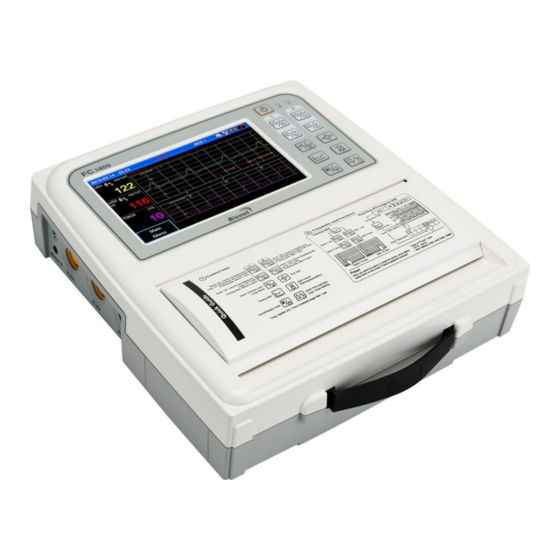
FC1400 Operation Manual FC1400 User Manual 4) Composition of FC1400 ▣ Top view ② ① ③ ④ ① Graphic display window: Part that displays the contents of measurements and condition of the equipment ② Alarm LED : Part that displays the status of alarm ③... - Page 23 FC1400 Operation Manual FC1400 User Manual ▣ Front view ① ① Hand Grip : Use when lifting and moving the equipment ▣ Rear view ② ④ ③ ① ① Power adaptor connector: Power adaptor of 18V, 2.8 A is connected ②...
- Page 24 Please instruct the operators to avoid contact with both the USB or LAN port area and the patient simultaneously. RISK OF ELECTRICAL SHOCKS – DO NOT OPEN THE DEVICE : Device disassembly is only authorized to individuals with Bionet service authorization. FC1400OM-2.04 24 / 95...
-
Page 25: System Installation
At this time, please check if the Power Cord has been installed properly. Storage Temperature : -10~+60°C Storage Pressure : 70(700)~106Kpa(1060mbar) Storage Humidity : 20~95%(without condition) FC1400 stand installation (Option) Insert the FC1400 stand to the stand hole on the underside of the FC1400 Stand hole FC1400OM-2.04 25 / 95... - Page 26 FC1400 Operation Manual FC1400 User Manual Operating procedure Turn on power to the equipment. Power will be turned on if the power switch on the front side of the main body is pressed for two seconds when power has been turned off; on the other hand, power will be turned off if the power switch is pressed for two seconds when power has been turned on.
- Page 27 FC1400 Operation Manual FC1400 User Manual After use Turn off the power switch and unplug the power cord. Take off the probes connected to the patient. Once the operation has been completed, clean the equipment and accessories to prevent malfunction.
-
Page 28: Chapter 3. Basic Operation
FC1400 Operation Manual FC1400 User Manual Chapter 3. Basic operation 1) System start Press the power switch on the main body for two seconds; power will then be turned on, with the company name displayed for around five seconds followed by the home screen. -
Page 29: Operation Panel
FC1400 Operation Manual FC1400 User Manual 4) Operation panel ① ② ③ ④ ⑤ ⑥ ⑦ ⑧ ⑩ ⑨ ⑩ ⑪ ⑫ ① AC power input LED: LED indicating the state of AC power connections ② Battery operation LED: LED indicating the state of battery charges ③... -
Page 30: Menu
FC1400 Operation Manual FC1400 User Manual ⑪ Home and function key: General screens and large value screens can be swapped; the function of a home key to move from a sub-menu to the main screen can be executed. ⑫ Printing start/stop key and Paper feeding key Short key : A. - Page 31 FC1400 Operation Manual FC1400 User Manual ▣ Value entry To enter a value, drag the cursor to the value using the wheel and then touch the selection key or the screen. ▣ Color selection and entry To select the color of a line or a numerical value, drag the cursor to the desired color and touch the selection key or color on the screen.
-
Page 32: Power Connection
FC1400 Operation Manual FC1400 User Manual 6) Power connection ▣ AC power If AC power is connected to the main body of the equipment, the Power LED on the front side of the equipment will emit a green light; if a battery has been installed, the power mode will be automatically changed to automatic charging mode, and the battery will be charged. - Page 33 FC1400 Operation Manual FC1400 User Manual ▣ Changes in the screen in relation to the state of battery connection The battery condition should be displayed in relation to connection of Battery and AC power and Battery condition as follow * No Battery...
- Page 34 When installed in the equipment and connected to AC power, the battery does not supply power in general. The lifetime of the battery may be shorter than 12 months. Bionet recommends detaching the battery from the monitor for storage until the equipment is moved.
-
Page 35: Operating Modes
FC1400 Operation Manual FC1400 User Manual 7) Operating modes There are 3 operating modes. Some are password protected. Monitoring mode: This is normal mode for monitoring patients. You can change elements such as alarm limits and so forth. When you discharge the patient, these elements return to their default values(preset value). -
Page 36: Chapter 4. Patient & Data Management
FC1400 Operation Manual FC1400 User Manual Chapter 4. Patient & data management Basic information necessary to identify patients is saved. 1) Patient registration This is a method of registering patients when the equipment is used as independent equipment. If the equipment is used without registering patients, patient IDs will be saved as Default values. -
Page 37: Edit Patient Information
FC1400 Operation Manual FC1400 User Manual < Registering a patient using “Search” > ① Touch “Patient” in the menu. ② Select “Search” to register a patient with records left in the Trace records. ③ By referring to the IDs, last names, and first names shown in the Patient List, touch the patient to be registered to select said patient. -
Page 38: Chapter 5. Fhr Measurement Using Us
FC1400 Operation Manual FC1400 User Manual Chapter 5. FHR measurement using US FHRs are measured by obtaining the heartbeat sounds of the fetus using ultrasonic Doppler effects and subsequently calculating and saving the heart rate per minute in real time. Since ultrasounds are reduced considerably in the air, please apply sufficient amounts of ultrasonic gel to the surface of US probes to remove any air layer before using US probes. - Page 39 FC1400 Operation Manual FC1400 User Manual ▣ How to measure FHRs ① Place a fixing belt below the waist of the patient. ② To remove air bubbles between the abdomen of the patient and the surface of the US probe, please apply a sufficient amount of ultrasonic gel to the US probe.
-
Page 40: Us Screen
FC1400 Operation Manual FC1400 User Manual 2) US screen If the US area on the screen is selected and touched, the following selection window pops up on the screen: ① Title ② FHR Volume Icon: This informs the user of the current state of the Volume; if this icon is touched, a volume adjusting window will be displayed. - Page 41 FC1400 Operation Manual FC1400 User Manual ▣ FHR Sound Volume adjustment Touch the Sound Volume menu. Select the value to be set from Off or volumes at levels 1~9. FHR sounds can be adjusted using the operation panel or LCD screen touch the volume adjusting icon and select a volume from the popup window.
- Page 42 FC1400 Operation Manual FC1400 User Manual ▣ Alarm limit Touch Alarm Limit section within FHR setting menu to set the alarm range of FHR. Set by either entering numbers or touching arrow keys. ▣ Alarm delay This is set up to prevent alarms from ringing when FHR values exceed the alarm range but only for a short time;...
-
Page 43: Chapter 6. External Measurement Of Uterine Contraction
FC1400 Operation Manual FC1400 User Manual Chapter 6. External measurement of uterine contraction UAs are measured using external attachment-type pressure sensors. A TOCO probe is attached to the abdomen of the patient to measure the relative pressures that vary with the uterine contraction of the patient, thereby recording the uterine activity. - Page 44 FC1400 Operation Manual FC1400 User Manual ▣ UA measurement ① Place a fixing belt below the back of the patient. ② Place a TOCO probe on the highest peak of the abdomen of the patient (Fundus: located around 10cm above the umbilicus) or the place that hardens first in the abdomen of the patient.
-
Page 45: Toco Screen
FC1400 Operation Manual FC1400 User Manual 2) TOCO screen If the TOCO area on the screen is selected and touched, the following selection window pops up on the screen: ② ① ③ ① Title TOCO: Displays only uterine contraction but not fetal movements TOCO+ FM: Displays both fetal movements and uterine contraction simultaneously ②... - Page 46 FC1400 Operation Manual FC1400 User Manual ▣ Auto Zeroing This is a function for initiating automatic adjustment of the zero point when a TOCO value is maintained below 0 for at least five seconds. ▣ Fetal Movement This is used to set up whether to output fetal movement-related graphs to the screen or through the printer.
-
Page 47: Chapter 7. Fetal Movement Measurement
FC1400 Operation Manual FC1400 User Manual Chapter 7. Fetal movement measurement Fetal Movements can be measured in two methods: automatic detections from data entered in ultrasounds and measurement by pressing a marker jack when the patient feels fetal movements. ▣ Method using a marker jack This is a method of recording fetal movements by relying on maternal perception for the time points of fetal movements by having the patient press the button on the marker jack. - Page 48 FC1400 Operation Manual FC1400 User Manual ▣ Marker jack ▣ Method using automatic fetal movement measurements The automatic fetal movement measurements extract information in proportion to the sizes and durations of fetal movement from the received ultrasonic Doppler signals and display the information along with information on uterine contraction.
-
Page 49: Chapter 8. Stimulator
FC1400 Operation Manual FC1400 User Manual Chapter 8. Stimulator When stimulator has been pressed, simulator symbol will be displayed on the screen. <LCD display> Warning A stimulator can be used such as the GE stimulator or GE compatible products. Please use a safety secured stimulator. -
Page 50: Chapter 9. Clinical Mark And Note
FC1400 Operation Manual FC1400 User Manual Chapter 9. Clinical Mark and Note To record clinical mark in real time, use Clinical Mark button. When Clinical Mark key is shortly pressed, Clinical mark will be entered, and Clinical Mark will be displayed when Trace range and Real time is printed. - Page 51 FC1400 Operation Manual FC1400 User Manual ▣ Entering Note When Clinical Mark key is long pressed, Note screen will be printed. Press OK after selecting related item from the list, and Trace and Real time Note will be printed. ▣ Adding Note Note lists can be added and edited by Users having Administrator rights.
-
Page 52: Chapter 10. Trace
FC1400 Operation Manual FC1400 User Manual Chapter 10. Trace The saved measurement results may be viewed using the Trace function. Data measured for 72 hours are saved. Trace data can be reprinted or copied as images to USB 1) Trace area ⑥... -
Page 53: Trace
FC1400 Operation Manual FC1400 User Manual 2) Trace ▣ Trace To view trace data, touch Trace in the main menu. : Trace Key ▣ Changing trace time Trace data times may be changed by moving the scroll bar on Trace, by using volume adjustment keys on the operation panel or by touching the left or right of trace window. -
Page 54: Setting Up Trace Modes
FC1400 Operation Manual FC1400 User Manual ▣ Exiting the Trace screen To view data entered in real time when the Trace screen is displayed, touch the Main Home of the Trace menu or the “screen switching or function key” on the operation panel. - Page 55 FC1400 Operation Manual FC1400 User Manual ▣ Data Save Trace a period of time, stored on a USB storage device. When you insert a USB storage device is displayed on the LCD screen on the right. Trace mode from the main menu, touch the “Data Save”...
-
Page 56: Chapter 11. Print
FC1400 User Manual Chapter 11. Print FC1400 has two Trace print function, real time and previous data print. In the printing process, print icon can be seen on the right top. Two types of Print icons, 'printing' and 'print stop', exist. -
Page 57: Trend Printing
FC1400 Operation Manual FC1400 User Manual ▣ Changing the type of printing paper To change the type of paper, touch the main menu Printer. Touch the item “Scale” in the menu and select the desired type of paper to change the type ▣... -
Page 58: Chapter 12. Alarm And Preset
FC1400 Operation Manual FC1400 User Manual Chapter 12. Alarm and preset Alarms are largely divided into patient condition alarms and product condition alarms. 1) Patient condition alarm Patient condition alarms will sound when the value exceeds the maximum and minimum limit values for alarms;... -
Page 59: Visual Alarm
FC1400 Operation Manual FC1400 User Manual 3) Visual Alarm Alarm messages appear in the Alarm Status Area on the screen. If more than one alarm occurred, messages are changed every two seconds, with an arrow displayed next to the messages. The colors of the alarm messages match the levels of the alarms. -
Page 60: Alarm Latching
FC1400 Operation Manual FC1400 User Manual 6) Alarm Latching Audible alarm will continue to ring until the situation is resolved. If no responsive action is taken, it will continue to ring until the user takes an appropriate action. Once the user takes action and alarm situation is over, both audible and visual alarm will disappear. -
Page 61: Preset
FC1400 Operation Manual FC1400 User Manual 8) Preset It is a function which standard settings can be only changed by authorized person. Volume adjusting function applies to current patient, and when device is restarted or moved to another patient, it turns on to preset function value. -
Page 62: Alarm Volume Adjustment
FC1400 Operation Manual FC1400 User Manual 9) Alarm volume adjustment Audible Alarms can be adjusted to 1~5 levels of volume or may be muted. ① Touch "Main Menu->Preset->Alarm Volume" ② Selected the desired volume on the popup window. ③ Check if the current alarm volume is displayed on the alarm icon on the screen. -
Page 63: Setting All Alarms On/Off
FC1400 Operation Manual FC1400 User Manual 10) Setting all alarms ON/OFF This function is either to activate or deactivate alarm for each parameter. Touch Main Menu->Preset- >Alarm On/Off and set the condition by pressing in Alarm Parameter window. Default Value: FHR1 : On... -
Page 64: Setting All Alarm Levels
FC1400 Operation Manual FC1400 User Manual 12) Setting all alarm levels This function allows users to select alarm levels for each parameter. Touch “Main Menu->Preset- >Alarm Level”, and click button on “Alarm Level” window to change, in order to set the default values, touch “Default”... -
Page 65: Chapter 13. Network
FC1400 Operation Manual FC1400 User Manual Chapter 13. Network To set up network configuration, touch the Network in the menu. IP : NewFC1400 Network information Central IP : Central server information Wireless setting If you use the Wireless LAN, wireless LAN module is inserted into the USB slot on the rear side, and the touch the Wireless menu, and the touch the central menu When “On”... - Page 66 FC1400 Operation Manual FC1400 User Manual Central setting If you set the state “ON” by touching “Central” button, the device can be connected to the Central. If you set the state “Off”, the connection will be terminated. Warning First, check the Wireless LAN module equipment to make sure that it is properly seated, before Central of state and Wireless change “On”...
-
Page 67: Chapter 14. General Setting
FC1400 Operation Manual FC1400 User Manual Chapter 14. General setting Go to “System” in the main menu to define the general settings. => The following is the setting menu: 1) Date changing To set up a date, touch the Date in the setting menu. -
Page 68: Version Information
FC1400 Operation Manual FC1400 User Manual 4) Version information To verify the version information, touch the “version” in the setting menu S/W Version UI : UI Software version F/W #1 : Fetal module firmware version F/W #2 : Printer module firmware version... -
Page 69: Marker Sound
FC1400 Operation Manual FC1400 User Manual 8) Marker sound Touch to turn ON/OFF the sound when clicking Marker. Refer to Chapter 7, Fetal movement measurement, for more information. 9) Factory Only the administrator can enter Factory mode. In order to change the content, request for A/S through Headquarter or agency. -
Page 70: Chapter 15. Nst
FC1400 Operation Manual FC1400 User Manual Chapter 15. NST The Non-Stress Test Timer measures the NST time that passed. This function helps users measure for the designated time only. 1) NST measurement ▣ Starting NST Touch “print key”. When the set NST time has passed, alarms will sound to inform the user that the NST measurement has been finished. -
Page 71: Chapter 16. Ctg Terms
FC1400 Operation Manual FC1400 User Manual Chapter 16. CTG terms CTG is interpreter function by FHR and TOCO. If you choose on, base FHR values will be printed out 10 minutes after you press print button. If you pressed print button after 10 minutes, CTG interpreter results will be printed out. -
Page 72: Ctg Measurement Results
FC1400 Operation Manual FC1400 User Manual 3) CTG Measurement results After measuring CTG, the result will be printed out as below. Middle Report Final Report FC1400OM-2.04 72 / 95... -
Page 73: Glossary Of Ctg Terms
FC1400 Operation Manual FC1400 User Manual 4) Glossary of CTG Terms ▣ Base FHR/ Average Base FHR Except Constant FHR, irregular FHR, extreme changed FHR, 25bpm exceed of base line difference cases, it should be progress more than 2 minutes as 10 minutes of FHR average data. -
Page 74: Acceleration
FC1400 Operation Manual FC1400 User Manual 5) ACCELERATION Visually apparent abrupt increase (onset to peak is < 30sec) of FHR above baseline. Peak is ≥ 15 bpm. Duration is ≥ 15 bpm and <2 min. Peak of 10 bpm and duration 10sec is acceleration FC1400OM-2.04... -
Page 75: Late Deceleration
FC1400 Operation Manual FC1400 User Manual 6) LATE DECELERATION Visually apparent gradual decrease (onset to nadir is ≥ 30 sec.) of FHR below baseline. Return to baseline associated with a uterine contraction. Nadir of deceleration occurs after the peak of the contraction. -
Page 76: Early Deceleration
FC1400 Operation Manual FC1400 User Manual 7) EARLY DECELERATION Visually apparent gradual decrease (onset to nadir is ≥ 30 sec.) of FHR below baseline. Return to baseline associated with a uterine contraction. Nadir of deceleration occurs at the same time as the peak of the contraction. -
Page 77: Variable Deceleration
FC1400 Operation Manual FC1400 User Manual 8) Variable DECELERATION Visually apparent abrupt decrease (onset to nadir is <30sec) in FHR below baseline. Decrease is ≥15 bpm. Duration is ≥ 2 min and < 10 min. FC1400OM-2.04 77 / 95... -
Page 78: Chapter 17. Message List
FC1400 Operation Manual FC1400 User Manual Chapter 17. Message list 1) Patient Alarm Short Msg Figure Msg From FHR* MEDIUM FHR* xxx < yyy FHR* FHR* LOW FHR* xxx>yyy FHR* 2) INOP Alarm Short Msg Figure Msg No Paper Main... -
Page 79: Chapter 18. Simple Troubleshooting
2) Performing periodic inspections Just like all kinds of medical equipment, please conduct safety inspections on FC1400 periodically (once a year). Refer to the service manual provided by the company for the inspection items. -
Page 80: Chapter 19. Product Specification
FC1400 Operation Manual FC1400 User Manual Chapter 19. Product specification General specification Dimension 296(w)x.305.5(H)x97.5(D)(Approx. 2.9Kg) 7” Wide (800 X 480) Display Method : Thermal Array Print Type : Roll type Print speed : 1,2,3cm/min,( Real time) Recorder 30 cm/min (Trace, 2,4 cm/min setting) -
Page 81: Intended Use
From the signals returned after being reflected by the heart of the fetus, FC1400 extracts Doppler frequencies that vary with the movements of the heart of the fetus to output changes in the heartbeats of the fetus as sounds for the analysis of the signals; thus detecting the heart rates and fetal movements of the fetus. -
Page 82: Appendix A. Manufacturer's Declaration - Electromagnetic
Manufacturer’s declaration - electromagnetic immunity The FC1400 system is intended for use in the electromagnetic environment specified below. The customer or the user of the FC1400 system should assure that it is used in such an environment Immunity test IEC 60601... - Page 83 FC1400 Operation Manual FC1400 User Manual The FC1400 system is intended for use in the electromagnetic environment specified below. The customer or the user of the FC1400 system should assure that it is used in such an environment Immunity test IEC 60601...
- Page 84 Recommended Separation Distances Between Portable and Mobile RF Communications Equipment the FC1400 system. The FC1400 system is intended for use in an electromagnetic environment in which radiated RF disturbances are controlled. The user of the FC1400 system can help prevent electromagnetic...
- Page 85 Guidance and manufacturer’s declaration - electromagnetic immunity The FC1400 system is intended for use in the electromagnetic environment specified below. The customer or the user of the FC1400 system should assure that it is used in such an environment Immunity test IEC 60601...
- Page 86 1) Model name (1) Model name: FC1400 2) Manufacturer’s company name and address (1) Company name: Bionet Co., Ltd. (2) Address: 5F, Shinsegae I&C Digital Center 61 Digital-ro 31 gil, Guro-gu, SEOUL 08375, REPUBLIC OF KOREA 3) Manufacturing business permission number and manufacturing item permission number (1) Manufacturing business permission no.:...
-
Page 87: Appendix B. Maintenance, Care, And Service
FC1400 Operation Manual FC1400 User Manual Appendix B. Maintenance, Care, and Service 1) Mechanical hazard Warning Ultrasound probes are highly sensitive medical instruments that can easily be damaged by improper handling. Use care when handling and protect from damage when not in use. - Page 88 Do not to touch signal input, signal output or other connectors, and the patient simultaneously. Refer servicing to qualified personnel of Bionet Co., Ltd. Power supply is specified as a part of ME Equipment. 4) Probe acoustic output hazard Warning Ultrasound can produce harmful effects in tissue and potentially result in patient injury.
-
Page 89: Appendix C. Ultrasound Power
FC1400 Operation Manual FC1400 User Manual Appendix C. Ultrasound Power Use of Diagnostic Ultrasound The American Institute of Ultrasound in Medicine (AIUM) has published a document entitled "Medical Ultrasound Safety". This three part document covers Bioeffects and Biophysics, prudent Use and Implementing ALARA. - Page 90 FC1400 Operation Manual FC1400 User Manual 4) Table Key Meaning IEC60601-2-37 / FDA&NEMA UD2,UD3 α Acoustic Attenuation Coefficient / Derating factor (usually 0.3 dB/cm-MHz) Aaprt Aaprt -12db Output Beam Area / Active aperture area Normalizing Coefficient Equivalent Aperture Diameter Pulse Beam Width / Beam diameter at –6 dB Equivalent Beam Diameter ƒawf...
- Page 91 FC1400 Operation Manual FC1400 User Manual Acoustic Output Tables MC65R1S – Pulsed Doppler Mode Index scan Non-scan Non-scan Aaprt<= 1 Aaprt > 1 Global Maximum : Index Value 0.0164842 0.00168143 0.0130577 0.00869565 Unit Associated pr.3 (MPa) 0.0164807 Acoustic (mW) Parameter...
-
Page 92: Appendix D. Abbreviation And Symbol
FC1400 Operation Manual FC1400 User Manual Appendix D. Abbreviation and Symbol Abbreviation and Symbol of manual or system operation is arranged in alphabetical order. Abbreviations alternating current Celsius cm, CM centimeter direct current electromagnetic compatibility electromagnetic interference Fahrenheit gram heart rate, hour... - Page 93 FC1400 Operation Manual FC1400 User Manual second Temp, TEMP temperature volt multiplier when used with a number (2X) Symbols & ° degree(s) > greater than < less than – minus number percent ± , +/- plus or minus FC1400OM-2.04 93 / 95...
- Page 94 Manufacturer name ※ This product is “medical equipment.” ※ Thank you for buying FC1400 ※ This product has passed thorough quality control and strict inspections. ※ The criteria for compensation in relation to repair, replacement, or refund for this product shall be governed by the “consumer damage compensation regulations”...
- Page 95 FC1400 Operation Manual FC1400 User Manual International Sales & service Bionet Co., Ltd. : 5F, Shinsegae I&C Digital Center 61 Digital-ro 31 gil, Guro-gu, SEOUL 08375, REPUBLIC OF KOREA Tel : +82-2-6300-6410 / Fax : +82-2-6499-7789 / e-mail: sales@ebionet.com Website: www.ebionet.com...
Need help?
Do you have a question about the FC1400 and is the answer not in the manual?
Questions and answers