Bionet Cardio P1 Service Manual
Hide thumbs
Also See for Cardio P1:
- Operation manual (123 pages) ,
- Quick manual (6 pages) ,
- Quick manual (2 pages)

Related Manuals for Bionet Cardio P1


Summary of Contents for Bionet Cardio P1
- Page 1 Cardio P1 SERVICE MANUAL Version 1.01 www.ebionet.com Copyright © 2023 By Bionet Co., Ltd. All rights reserved...
- Page 2 V 1.01 Revision History Edition Date Page Comment Ver. 1.00 2022-02-08 Initial Release Ver. 1.01 2023-05-17 Change Logo 2023. 05 2 / 53 Doc. # : BN_CP1_SCM_305...
-
Page 3: Table Of Contents
V 1.01 - TABLE OF CONTENTS – Section 1. General Information ....................4 1-1. Introduction ..................................4 1-2. Features of the equipment ............................4 1-3. Equipment description .............................. 5 1-4. System Installation ..............................13 1-5. Terms of Warranty ...............................15 1-6. Specification .................................16 Section 2. -
Page 4: Section 1. General Information
The CardioSync is installed on a standalone PC. For all configurations, an independent PC is used that can be positioned for patient convenience. For device to ECG measurement is Cardio P1. 1-2. Features of the equipment - Waves of ECG in 12 channels are configured with various channels in 3 channels + 3 rhythms, 3 channels + 1 rhythm, 6 channels + 1 rhythm and 12 channels and reports are printed on the PC. -
Page 5: Equipment Description
The CardioSync system is comprised of the following components. CardioSync System 1) CardioSync - Software that analyzes and records the measured ECG - Installed on a PC. 2) Cardio P1 - Device to ECG measurement 2023. 05 5 / 53 Doc. # : BN_CP1_SCM_305... - Page 6 Make sure to open the package box and see if the following components are contained. In addition, make sure to see if body or components are damaged. ① Body (1EA) - Cardio P1 90.75(W) x 103.5(H) x 24.93(D)mm ② Patient Cable (1EA) - Length 1,400mm (Max) ③...
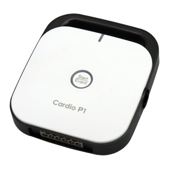
- Page 7 V 1.01 Main Unit ▣ Top View ① Indication Part (LED) : Part showing the power connection status of a product ② Indication Part (LED) : Part that informs the lead connection status ③ Function Switch : Start record (push more than 3 seconds), event marker key ▣...
- Page 8 V 1.01 ▣ Side View ① Power (USB Data) Cable Connection Port ▣ Rear View ① ECG Cable Connection Port Warning If a stand for anchoring the device is damaged, or if a product is not anchored, there is a risk of electrocution. Make sure to immediately stop using the product and request manufacturer or seller for the repair.
- Page 9 V 1.01 Initial Screen After completing all installation and running the program, you will see a menu to select the system version, company name, 'ECG', 'Patient', 'Worklist', and 'File' on the screen. To select an ECG, find the menu box and click the selection box on the screen. : ECG : Patient : Worklist...
- Page 10 ⑥ Display the real-time diagnosis name display ⑦ Indicate study queue (sending failure list management) icon ⑧ Access status of external devices (barcode reader) ⑨ Access status of Cardio P1 ⑩ Menu button for network connection status and setup ⑪ Button for expand/collapse Side Menu ⑫...
- Page 11 V 1.01 10) Show contact us 11) Logout button 12) Close button ⑬ Side Menu bar 1) Indicate heart rate 2) AUTO button 3) Menu button for indicating ECG record mode (one of the 10s, 1m, 3m, 5m, 10m, 20m and 30m) and setup 4) Menu button for indicating or setting up signal size 5) Menu button for indicating or setting up print speed Notes...
- Page 12 V 1.01 Function Key Panel ③ ② ① Push Buttons ⚫ Auto / Event. 1. Long Press (more than 3 seconds) Perform the operation that is the most frequently performed in the saving, transmission, and printing of data ① in the ECG diagnosis test with one key 2.
-
Page 13: System Installation
Power Connection Plug the power (USB data) cable into the USB port of the PC and the side connection cord of the Cardio P1 and the device will work. Patient Cable Connection - Connect the patient cable to the patient cable connection port located on the bottom of the main unit. - Page 14 ⚫ If the device is used as a layer-2-switch or layer-3-switch, the port settings must be configured on the network switch. “Bionet device” must be configured so that the network settings are compatible with the specifications of the operating organization.
-
Page 15: Terms Of Warranty
“Consumer’s protection law” noticed by ministry of finance and economy. - Cardio P1 is warranted by Bionet Co., Ltd. to be free from defects in material and workmanship for one year (two years in Europe) from date of purchase. -
Page 16: Specification
V 1.01 1-6. Specification ECG Leads Simultaneous 12 channel ECG and acquisition Recording 3CH+3RHY, 3CH+1RHY, 6CH+1RHY, 12CH, 6CH+ST map Channel 1CH Long Time (1min, 3min, 5min,10min, 20min, 30min) Special Beat Report (Text, Guide, Vector, ST map) Gain 2.5, 5, 10, 20, Auto (I~aVF: 10, V1~V6: 5) mm/mV Printing Speed 5, 12.5, 25, 50, 100 mm/sec Sampling Rate... - Page 17 V 1.01 Storage/ Ambient temperature: -10 to 60℃ Ship Relative humidity: 20 to 95% Atmospheric pressure: 50 to 106KPa Dimensions Body - 90.75(W) x 103.5(D) x 24.93(H)mm - Approx. 110g Standard Patient Cable (1EA), Limb Electrodes (1SET), Accessory Chest Electrodes (1SET), Power (USB Data) Cable (1EA), Hanger (1EA), Silicone Pad (1EA), ECG Gel (1EA), ECG Diagnosis Guide (1EA), USB Lock Key (1EA) Warning...
-
Page 18: Section 2. Troubleshooting
→ Re-solder the connector. Case2. Power will not ● When applying power to Cardio P1, the voltage of pin2 of J5 should turn on. always be 5V. 1) Is the pin’s voltage is 5V→ Yes → replace the base board. -
Page 19: Wave Printing
V 1.01 2-2. Wave Printing Problem Resolution 1. The normal wave patterns will show if output is requested after the patient is stabilized by showing the ECG wave on the CardioSync display. 2. Check connection of the limb and the chest electrodes to the patient body parts. - Page 20 V 1.01 Problem Resolution 1. This problem occurs when the filter value is not corrected. 2. Since the noise occurs as in problems 2-1, if the AC filter is turned off or set at different frequency from the power source, the system must be set at 50Hz or 60Hz to correspond to the input power.
- Page 21 V 1.01 Problem Resolution 1. This problem occurs when the chest electrode is not properly in contact with the body. 2. Check with simulator there is any cut on the patient cable. 3. Check there is any damage to the chest electrode. 4.
- Page 22 V 1.01 1. If some wave patterns are too small as shown in the problem 5, the problem is most likely to be with the patient cable, limb or chest electrodes. 2. If the problem is not with the accessories, then the main board is the problem.
-
Page 23: Diagnosis
V 1.01 2-3. Diagnosis Problem Resolution 1. If disease is diagnosed, abnormal ECG always appears. 2. LVH occurs when the sum of one of V1 or V2 and one of V5 or V6 is 3.5 or higher. 3. Upgrade to the latest version of the software. -
Page 24: Filter
V 1.01 2-4. Filter Baseline Filter ⚫ Baseline drift is caused by a patient’s breathing. ECG signal is overlapped on a large parabola. If you want to set Baseline drift, can be applied as off, 0.05Hz, 0.1Hz and 0.2Hz in the base menu. - Page 25 V 1.01 Low Pass Filter ⚫ When ECG is not clear even after all three filters are set to ON, the use of low frequency filter will produce clear ECG signal. The low frequency filter can be set to 40Hz, 100Hz, and 150Hz and OFF.
-
Page 26: Trouble Shooting Guide
V 1.01 2-5. Trouble Shooting Guide 1) Power is off The power is off Does the power (USB Change the power data) cable (USB data) cable break down? Normal operation Does the main power Change the main connector power connector break down? Ask the manufacturer... - Page 27 2) When the device is not connected even when the program is turned on Powered on but not connected to the program Are CardioSync and Did you connect Cardio P1 up-to-date after or compatible with reconnecting? each other? Are the ports...
- Page 28 V 1.01 3) ECG wave does not come out or it's very small ECG wave does not come out or small Is the patient Reconnect the cable patient cable connecter carefully correctly? Is the electrode Cleanse the connected to electrode with the patient alcohol or water, cable...
-
Page 29: Section 3. Adjustment
V 1.01 Section 3. Adjustment 3-1. Lead Fault - If ‘RA’ lead is fault, not all the lead waves are shown. - If ‘LA’ lead is fault, I, V1 ~ V6 waves are not shown. - If ‘RL’ lead is fault, lead fault message is not shown. All the lead waves can be shown. -
Page 30: Filter Setting
V 1.01 3-2. Filter Setting To set the filter, click the 'Setup' item on all screens and go to ECG -> Filter tab. 2023. 05 30 / 53 Doc. # : BN_CP1_SCM_305... -
Page 31: Section 4. Block Diagram/Description
V 1.01 Section 4. Block Diagram / Description 4-1. Circuit Block Diagram Analog Part 5V, 3.3V Shield Power Driver 6 Pin Trans- Port ceiver Pace- maker Detector Indicator Fuction Indicator LED x 2 Base Board 2023. 05 31 / 53 Doc. -
Page 32: Size And Weight
V 1.01 4-2. Size and Weight Size ⚫ - 90.75(W) x 103.5(D) x 24.93(H)mm Weight: approx. 85g ⚫ 2023. 05 32 / 53 Doc. # : BN_CP1_SCM_305... -
Page 33: Section 5. Disassembly And Assembly
V 1.01 Section 5. Disassembly and Assembly 5-1. Module Description Kapton Tape (2ea) Base Board Power Cable Base Board Power Cable Patient Cable Patient Cable 2023. 05 33 / 53 Doc. # : BN_CP1_SCM_305... - Page 34 V 1.01 1) Base(Power + Analog) Board <Top> <Bottom> A: Switch B: MCU C: Voltage Regulator D: Transformer E: Inverter F: Optocoupler G: Power Cable Connector H: Patient Cable Connector I: Front-End for Biopotential Measurements (ADS1298) 2023. 05 34 / 53 Doc.
-
Page 35: Block Diagram & Cable
V 1.01 5-2. Block Diagram & Cable 1) Transceiver & Analog Block Diagram Lead Fault Pacemaker Shield Blue & Red Detector Driver Signal PACE Signal USB_ANA UART_ANA UART_ANA Analog ECG USB to UART Optical Isolator AFE Circuit USB Port Control ANA_3.3V SYS_5V 3.3V LDO... - Page 36 V 1.01 2) Cable A: USB_CON Cable B: ECG_CON Cable 2023. 05 36 / 53 Doc. # : BN_CP1_SCM_305...
-
Page 37: Disassembly
V 1.01 5-3. Disassembly Step1. Removing the Hanger a. Pull the silicone pad out of the hanger part. 2023. 05 37 / 53 Doc. # : BN_CP1_SCM_305... - Page 38 V 1.01 Step2. Removing the Silicone Stopper a. Remove the two silicone stopper using tweezers, etc. Step3. Removing the Bottom Case a. Remove the 2 tab screws 2023. 05 38 / 53 Doc. # : BN_CP1_SCM_305...
- Page 39 V 1.01 2023. 05 39 / 53 Doc. # : BN_CP1_SCM_305...
- Page 40 V 1.01 b. Remove the bottom case by pulling it from the bottom. 2023. 05 40 / 53 Doc. # : BN_CP1_SCM_305...
- Page 41 V 1.01 Step4. Removing the Top Case a. Remove the 3 tap screws 2023. 05 41 / 53 Doc. # : BN_CP1_SCM_305...
- Page 42 V 1.01 b. Remove the top case by sliding the upper part of the top case. 2023. 05 42 / 53 Doc. # : BN_CP1_SCM_305...
- Page 43 V 1.01 Step5. Replacing the Base Board a. Remove and disconnect the cable from the connector b. Remove the Kapton Tape 2023. 05 43 / 53 Doc. # : BN_CP1_SCM_305...
-
Page 44: Assembly
V 1.01 Step6. Remove the side cover a. Remove the power cable nut b. Disconnect the patient cable c. Remove the side cover by pulling it from the marked area. 5-4. Assembly Assemble the reverse way from Step.6 to Step.1 2023. -
Page 45: Section 6. Replaceable Parts List And Accessory
V 1.01 Section 6. Replaceable Parts List and Accessory 6-1. Replaceable Part List < Cardio P1 Ass’y > 2023. 05 45 / 53 Doc. # : BN_CP1_SCM_305... -
Page 46: Section 7. Base Board Connector
V 1.01 Section 7. Base Board Connector 7-1. Power Connector Pin Description Name VSYS_5.0V DATA- DATA+ 7-2. Patient Cable Connector Pin Description Name NREF 2023. 05 46 / 53 Doc. # : BN_CP1_SCM_305... -
Page 47: Section 8. Pcb Part Disposition
V 1.01 Section 8. PCB Part disposition 8-1. Base Board < Top > <Bottom> 2023. 05 47 / 53 Doc. # : BN_CP1_SCM_305... -
Page 48: Section 9. Software Install
V 1.01 Section 9. Software Install 9-1. Software Minimum Requirement Install the program on a PC that meets the minimum specifications below. Operation System Window 10 Core2Duo 1.86GHz 2 GB Graphics Adapter VGA RAM 256 MB 1,600 x 900 Hard Drive ... -
Page 49: How To Install The Software
V 1.01 9-2. How to install the Software Add software for the description below. ① Close every application before beginning installation. ② Execute “SqlLocalDB.msi” under your CD-ROM drive, download folder or USB memory. ③ Follow each instruction on each step. <... - Page 50 V 1.01 <Stop 3 > < Step 4 > < Step 5 > ④ Execute “setup.exe” or “CardioSync ECG_X.XX.XXX_YYYYMMDD.msi” under your 2023. 05 50 / 53 Doc. # : BN_CP1_SCM_305...
- Page 51 V 1.01 CD-ROM drive, download folder or USB memory. ⑤ Follow each instruction on each step. < Step 1 > < Step 2 > 2023. 05 51 / 53 Doc. # : BN_CP1_SCM_305...
- Page 52 V 1.01 < Step 3 > < Step 4 > < Step 5 > 2023. 05 52 / 53 Doc. # : BN_CP1_SCM_305...
- Page 53 Toll Free: 1-877-924-6638 / Fax: 1-714-734-1761 / E-mail: support@bionetus.com Website: www.bionetus.com European sales & service representative Bionet Europe GmbH 2Li Bessemerstr. 51, D-12103 Berlin, Germany Tel: +49-30-240-374-52 / E-mail: bionetEU@ebionet.com Website: www.ebionet.com Bionet Co., Ltd Model Name: Cardio P1 2023. 05 53 / 53 Doc. # : BN_CP1_SCM_305...
Need help?
Do you have a question about the Cardio P1 and is the answer not in the manual?
Questions and answers