Table of Contents
Advertisement
Quick Links
Technical Support and E-Warranty Certificate
www.vevor.com/support
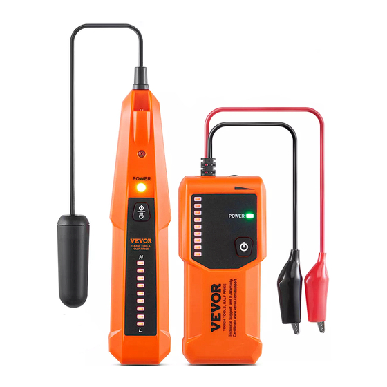
Cable Locator
INSTRUCTION SHEET
MODEL: EM2423
We continue to be committed to provide you tools with competitive price.
"Save Half", "Half Price" or any other similar expressions used by us only represents an
estimate of savings you might benefit from buying certain tools with us compared to the major
top brands and does not necessarily mean to cover all categories of tools offered by us. You
are kindly reminded to verify carefully when you are placing an order with us if you are
actually saving half in comparison with the top major brands.
Advertisement
Table of Contents

Subscribe to Our Youtube Channel
Related Manuals for VEVOR EM2423


Summary of Contents for VEVOR EM2423
- Page 1 Cable Locator INSTRUCTION SHEET MODEL: EM2423 We continue to be committed to provide you tools with competitive price. "Save Half", "Half Price" or any other similar expressions used by us only represents an estimate of savings you might benefit from buying certain tools with us compared to the major top brands and does not necessarily mean to cover all categories of tools offered by us.
- Page 2 This is the original instruction, please read all manual instructions carefully before operating. VEVOR reserves a clear interpretation of our user manual. The appearance of the product shall be subject to the product you received. Please forgive us that we won't inform you again if there are any technology or software updates on our product.
- Page 3 Warning-To reduce the risk of injury, user must read instructions manual carefully. This device complies with Part 15 of the FCC Rules. Operation is subject to the following two conditions:(1)This device may not cause harmful interference, and (2)this device must accept any interference received, including interference that may cause undesired operation.
- Page 4 WARNING ● To avoid and prevent electric shock, burn or personal injury, please read this manual carefully. ● To avoid electric shock, do not touch any naked conductor with hand or skin; and do not ground yourself while using the instrument. ●...
- Page 5 PRODUCTINSTRUCTION Transmitter Figure 1 1. Black alligator clip Used to connect to the earth or ground. 2. Red alligator clip Used to connect to the wire to be tracked. 3. Transmit signal adjustment knob Used to adjust the strength of the transmit signal. 4.
- Page 6 5. Transmit signal indicator LEDs 6. " " Button Press and hold this button to turn on or off the transmitter. Receiver Figure 2 1. Illumination lamp 2. Headphone jack - 5 -...
-
Page 7: How To Use The Transmitter
3. Power indicator LED 4. " " Button Press and hold this button to turn on or off the receiver. When the receiver is on, briefly press this button to turnon or off the illumination lamp. 5. Signal strength indicator LEDs The higher the signal strength detected, the more the red indicator LEDs light up. - Page 8 When the transmitter is turned on, it generates a specific tracing signal on the wire, creating an electrical current within the wire. This electrical current flows along the wire, passes through the grounding connection to the earth, and returns to the transmitter. The connection method for the transmitter is shown in Figure 3.
- Page 9 Warning: Before connecting the transmitter, ensure that all equipment are disconnected from the wires to be traced. To avoid electric shock, before turning on the transmitter, connect the red alligator clip to the wire you want to trace and the black alligator clip to the earth or ground.
-
Page 10: Low Battery Indication
5. Low Battery Indication When the green power indicator LED flashes, the battery in the transmitter is not high enough and you must replace it immediately; otherwise the transmitter will not operate normally. How to Use the Receiver 1. Turning on the Receiver Press and hold the "... - Page 11 of the signal detected by the receiver will change. The volume of the buzzer sound and the number of lit signal strength indicator LEDs will also change accordingly. There are two accepted methods to trace and locate wires: Peak Tracing Method and Null Tracing Method. Null Tracing Method When using the Null Tracing Method, the probe of thereceiver should be vertical and point to the wire.
- Page 12 Peak Tracing Method When using Peak Tracing Method, the probe of the receivershould be parallel to the ground surface and be vertical to thewire to be traced (see Figure 5). When the probe is directlyover the wire being traced, it will detect the strongest signal.At this point, the buzzer emits the loudest sound, and the highestnumber of red signal strength indicator LEDs will be lit.When you move the receiver's probe from directly over the wireto...
- Page 13 4. Turning on/off the Illumination Lamp When the receiver is on, you can briefly press the " " button to turn on or off the illumination lamp. 5. Using the Headphone The receiver can be used with headphones. When using itin a noisy environment, you can insert the headphone pluginto the headphone jack on the receiver to assist in tracingand locating wires or cables.
- Page 14 The signal of the transmitter and receiver is adjusted to the maximum. Trace and locate the wire by means of the signal intensity indication ( buzzer sound and red indicator LEDs on thereceiver ). When moving the receiver slowly across the wireto be traced, the signal intensity changes considerably.
- Page 15 Note: Make sure that the connection to the ground is far away from the wire to be traced. The max. tracing depth is about 2 to 3 feet. The tracing depth strongly depends on the ground conditions. During the tracing process, if the environment is excessively noisy, you can use headphones to listen to signal changes.
- Page 16 At this time, appropriately reduce the sensitivity until the receiver just receives the signal from the transmitter, and this area is the break of the wire. Red alligator clip Black alligator clip Figure 7 Note: Make sure that the connection to the ground is far away from the wire to be traced.
- Page 17 Checking Line Short-circuit Requirements The cable must be without voltage. Connect the alligator clips of the transmitter to two known short-circuit wires respectively as shown in Figure 8. The signal of the transmitter and receiver is adjusted to the maximum. Black alligator clip Red alligator clip...
-
Page 18: Specification
Adjust the sensitivity of the receiver properly can accurately locate the short-circuit point of the detected wire. Note: During the tracing process, if the environment is excessively noisy, you can use headphones to listen to signal changes. SPECIFICATION Transmitter Output Signal: 440kHz 15kHz Battery: 9V battery, 6F22 or equivalent, 1 piece Operating Environment: Temperature: 0°C to 40°C Relative Humidity: <... -
Page 19: Battery Charging/Replacement
Tracing Wire Length: 0 to 300m Headphone Jack: 3.5mm Battery: 9V battery, 6F22 or equivalent, 1 piece Operating Environment: Temperature: 0°C to 40°C Relative Humidity: < 70% Storage Environment: Temperature: -20°C to 60°C Relative Humidity: < 80% IP Degree: IP20 Operating Altitude: 0 to 2000 meters Size: 200mm x 40mm x 30 mm ( for main body only ) Weight: About 179g ( including battery ) - Page 20 Replace the old battery with a new one of the same type, make sure that the polarity connections are correct. Reinstall the battery cover and the screw. Warning: To avoid electric shock, turn off the transmitter and then disconnect the transmitter from any wire or cable before opening the battery cover or case of the transmitter.
-
Page 21: General Maintenance
MAINTENANCE Warning The instrument is not waterproof. Do not let water or any liquid enter the case. Before cleaning the instrument, turn off the instrument and disconnect the instrument from any wire/cable . Cleaning Periodically wipe the case with a damp cloth. Do not use abrasives or solvents. - Page 22 ACCESSORY 1. Headset: 1 piece 2. 9V 6F22 battery: 2 piece 3. Carrying bag: 1 piece 4. Manual: 1 piece 5. Screwdriver: 1 piece NOTE This manual is subject to change without notice. Our company will not take the other responsibilities for any loss. The contents of this manual can not be used as the reason to use the instrument for any special application.
- Page 23 DISPOSAL OF THIS ARTICLE Dear Customer, If you at some point intend to dispose of this article, then please keep in mind that many of its components consist of valuable materials, which can be recycled. Please do not discharge it in the garbage bin, but check with your local council for recycling facilities in your area.
- Page 24 Technical Support and E-Warranty Certificate www.vevor.com/support...
Need help?
Do you have a question about the EM2423 and is the answer not in the manual?
Questions and answers