
Subscribe to Our Youtube Channel
Related Manuals for WAGO Eco 2 Series


Summary of Contents for WAGO Eco 2 Series
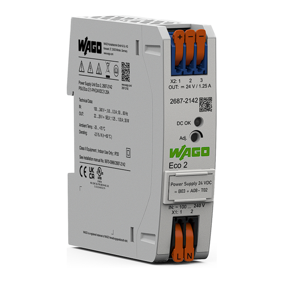
- Page 1 Power Supplies Power Supply Eco 2; 1-phase, 24 VDC, 1.25 A, 30 W 2687-2142 Product manual | Version 1.0.0...
- Page 2 We wish to point out that the software and hardware terms as well as the trademarks of companies used and/or mentioned in the present manual are generally protected by trademark or patent. WAGO is a registered trademark of WAGO Verwaltungsgesellschaft mbH. Product manual | Version: 1.0.0 Power Supply Eco 2...
-
Page 3: Table Of Contents
2687-2142 Table of Contents Table of Contents Provisions......................... 5 Intended Use ...................... 5 Typographical Conventions.................. 6 Legal Information .................... 8 Security .......................... 9 General Safety Rules .................... 9 Electrical Safety....................... 9 Mechanical Safety .................... 10 Thermal Safety ...................... 10 Indirect Safety ....................... 10 Properties ........................ 11 Introduction...................... - Page 4 Table of Contents 2687-2142 Connectors ...................... 27 6.1.1 Conductor Termination ................. 27 Operation ........................ 29 Setting the Output Voltage via Potentiometer ............ 29 Notes on Operation...................... 30 Inrush Current ....................... 30 Parallel Connection (on the Output Side).............. 30 Short-Circuit and Overload Behavior .............. 30 Derating.........................
-
Page 5: Provisions
The terms set forth in the General Business and Contract Conditions for Delivery and Service of WAGO Kontakttechnik GmbH & Co. KG and the terms for software products and products with integrated software stated in the WAGO Software License Contract –... -
Page 6: Typographical Conventions
Provisions 2687-2142 • The deficiency (hardware and software configurations) is due to special instructions. • Modifications to the hardware or software have been made by the user or third parties that are not described in this documentation and that has contributed to the fault. Individual agreements always have priority. - Page 7 2687-2142 Provisions Lists • Lists, first level – Lists, second level Figures Figures in this documentation are for better understanding and may differ from the actual product design. Notes DANGER Type and source of hazard Possible consequences of hazard that also include death or irreversible injury •...
-
Page 8: Legal Information
Third-party products are always mentioned without any reference to patent rights. WAGO Kontakttechnik GmbH & Co. KG, or for third-party products, their manufacturer, retain all rights regarding patent, utility model or design registration. -
Page 9: Security
• Observe permissible temperature range of connecting cables. • Only clamp one conductor to each connection terminal. If several conductors must be clamped, wire them using an upstream wiring assembly (e.g., WAGO Through Termi- nal Blocks). Product manual | Version: 1.0.0... -
Page 10: Mechanical Safety
• The product contains no parts that can be serviced by the user. Always have all ser- vice, maintenance and repair work performed by specialists authorized by WAGO. • Observe possible different technical specifications for mounting that does not corre- spond to the specified mounting position. -
Page 11: Properties
Properties Properties 3.1 Introduction The WAGO Power Supplies Eco 2 Series 2687 are switched mode Power supplies with a wide range of uses. They include all important basic functions and are available in differ- ent performance classes and widths. The Power supplies are fitted on a DIN-rail. With their slim design, they are suitable for use both in the control cabinet and in a compact distribution box. -
Page 12: Type Plate
Properties 2687-2142 Position Comment Details Potentiometer for setting the output voltage 8 Control elements [} 14] between 22 … 29 VDC Type plate 8 Type plate [} 12] Marker carrier 8 Accessories [} 34] Input X1 (L N) 8 Connections [} 13] Latch for mounting to /removal from DIN rail 3.3 Type plate Figure 2: Type plate Table 3: Legend for Figure “Type Plate”... -
Page 13: Connections
2687-2142 Properties 3.4 Connections 3.4.1 Connectors The supply lines are connected on the input and output side using the WAGO PCB termi- nal blocks with levers: • Input side: 2-pole • Output side: 3-pole Note the maximum permissible connection cross-sections of the power cables (see 8 Technical data... -
Page 14: Indicators
Properties 2687-2142 Position Description Termination 2 “-” for output voltage Lever 3.5 Indicators The indicators are located on the front of the product. The “DC OK” LED indicates the status of the output voltage U Figure 5: “DC OK” LED Table 6: Legend for “LED, DC OK” Figure Description State Explanation... -
Page 15: Input
2687-2142 Properties 25 mm 97 mm X2: 1 OUT: 24 V / 1.25 A 2687 2142 DC OK Adj. Eco 2 Power Supply 24 VDC B03 + A08 - T02 IN: ~ 100 ... 240 V X1:1 Figure 7: Dimensions Table 8: Technical Data – Clearances Mounting Direc- Front side Clearance from... -
Page 16: Output
Properties 2687-2142 Table 11: Technical Data – Inrush Current Property Value 1)2) Inrush current (typ.) 230 VAC ≤ 10 A (after 1 ms) Cold start, at room temperature of 25 °C After 1 ms at nominal load Table 12: Technical Data – Mains Failure Buffering Time Property Value Mains failure buffering time, typ. - Page 17 2687-2142 Properties Property Value See “Hiccup Mode” Figure; t = 35 ms / t = 310 ms See “Switch-on Time” Figure (VDC) Constant Power Mode 100% 105% 135% 140% 160% OUT (ADC) normal Overload Mode (105 % up to 135 %) Constant Power Mode Short Circuit Protection (140 % up to 160 %)
-
Page 18: Efficiency/Power Loss
Properties 2687-2142 Input Voltage Output Voltage Switch-on Time Figure 10: Turn-on Time Table 15: Technical Data – Output Side Connection Property Value Connection Technology 2604 Series (see 8 Appendix [} 34]) Cross-section Solid 0.2 … 4 mm² / 24 … 12 AWG Fine-stranded 0.2 … 4 mm² / 24 … 12 AWG Insulated ferrule with plastic collar 0.25 …... -
Page 19: Mtbf/Lifespan
2687-2142 Properties Efficiency [%] Figure 11: Efficiency at 230 VAC Power loss [W] Figure 12: Power loss at 230 VAC 3.7.5 MTBF/Lifespan Table 17: Technical Data – MTBF/Lifespan Property Value MTBF (IEC 61709) 25 °C > 1,000,000 h 3.7.6 Environment requirements Table 18: Technical Data ‒ Environmental Conditions Property Value Surrounding air temperature, operation... -
Page 20: Product Protection
Properties 2687-2142 Property Value Temperature coefficient ≤ ±0.005 %/K Derating (operating altitude) Elevation above sea level, max. 5000 m Overvoltage category III (≤ 2000 m a. s.l.) II (> 2000 m a. s.l.) Vibration according to IEC 60068-2-6 5 Hz ≤ f ≤ 8.4 Hz: 3.5 mm , 8.4 Hz ≤ f ≤ 150 Hz: 1g Shock according to IEC 60068-2-27 15 g, 11 ms, 3 shocks per axis (18 shocks in total) Pollution degree according to IEC/EN 60664-1... -
Page 21: Safety
UL 61010-2-201 SEMI F47 (For U_in ≥ 180 VAC) Note More information on approvals You can find detailed information on the approvals online at: ü www.wago.com/<item number> 3.8.2 Standards The product meets the following standards: Table 22: Standards: Mechanical and Climatic Environmental Conditions... -
Page 22: Special Requirements
Properties 2687-2142 Table 23: Standards: EMC – Immunity to Interference Standard Title EN IEC 61204-3 Low-Voltage Switch Mode Power Supplies – Part 3: Electromagnetic Com- patibility (EMC) EN IEC 61000-6-2 Part 6-2: Generic standards – Immunity for industrial environments EN 61000-4-2 Part 4-2: Testing and measurement techniques –... -
Page 23: Transport And Storage
2687-2142 Transport and Storage Transport and Storage The original packaging offers optimal protection during transport and storage. • Store the product in suitable packaging, preferably the original packaging. • Only transport the product in suitable containers/packaging. • Make sure the product contacts are not contaminated or damaged during packing or unpacking. -
Page 24: Installation And Removal
Installation and Removal 2687-2142 Installation and Removal NOTICE Avoid electrostatic discharge! The products are equipped with electronic components that may be destroyed by electro- static discharge when touched. Please observe the safety precautions against electro- static discharge per DIN EN 61340-5-1/-3. When handling the products, please ensure that environmental elements (personnel, work space and packaging) are properly grounded. - Page 25 2687-2142 Installation and Removal Mounting on the DIN Rail Mount the product per EN 60715 by snapping it onto the DIN rail without any tools. Figure 15: Mounting the Product on the DIN rail 1. Tilt the product slightly. 2. Place the product, with its DIN rail guide, on the top edge of the DIN rail. 3.
- Page 26 Installation and Removal 2687-2142 1. To remove the product, pull down the DIN rail mount/removal latch. ð Use a screwdriver or an operating tool. ð The product is now unlocked. 2. Tilt the forward forward and unhook it from the DIN rail. Product manual | Version: 1.0.0 Power Supply Eco 2...
-
Page 27: Connection
6.1 Connectors The supply lines are connected on the input or primary side and on the output or sec- ® ondary side via the WAGO PCB Terminal Blocks with Push-in CAGE CLAMP connection 8 Connections and levers of the 2604 Series (see [} 13]):... - Page 28 2687-2142 If more than one conductor must be routed to one connection, these must be connected in an up-circuit wiring assembly; for example, using WAGO Through Terminal Blocks. Direct Insertion of Connectors The following conductors can be inserted directly without tools: •...
-
Page 29: Operation
2687-2142 Operation Operation 7.1 Setting the Output Voltage via Potentiometer 8 Control elements The potentiometer [Adj.] (see [} 14]) can be used on the front of the product to set the output voltage between 22 … 29 VDC: • Turning clockwise increases the output voltage. •... -
Page 30: Notes On Operation
Notes on Operation 2687-2142 Notes on Operation 8.1 Inrush Current If several products are connected in parallel and supplied on the input side using the same circuit, higher inrush currents can result. In this case, the use of auxiliary relays, which cause a time delay in startup, is recommended. -
Page 31: Derating
2687-2142 Notes on Operation (VDC) Constant Power Mode 100% 105% 135% 140% 160% OUT (ADC) normal Overload Mode (105 % up to 135 %) Constant Power Mode Short Circuit Protection (140 % up to 160 %) Auto Recovery Figure 19: Output Characteristics Table 28: Legend for the “Output Characteristics”... -
Page 32: Maintenance
Permitted repairs are limited to the measures listed in these operating instructions. Should a fault occur nonetheless, return the product to WAGO for repair. Provide the fol- lowing information: • Type of fault •... -
Page 33: Decommissioning
2687-2142 Decommissioning Decommissioning 9.1 Entsorgung und Recycling Table 29: WEEE Mark Logo Description Electrical and electronic equipment may not be disposed of with household waste. This also applies to products without this mark. Electrical and electronic equipment contain materials and substances that can be harmful to the environment and health. -
Page 34: Appendix
Appendix 2687-2142 Appendix 10.1 Accessories Details on accessories are available online at ü www.wago.com. The following accessories are available for the product: Accessories – Tools Table 30: Accessories – Tools Description Designation Item number Operating tool for setting the potentiometer Screwdriver PH0 210-769 Accessories –... - Page 35 2687-2142 Appendix ® • KNX is a registered trademark of the KNX Association cvba. ® • Linux is a registered trademark of Linus Torvalds. ® • LON is a registered trademark of the Echelon Corporation. ® • Modbus is a registered trademark of Schneider Electric, licensed for Modbus Organi- zation, Inc.
- Page 36 List of Tables 2687-2142 List of Tables Table 1 Complete instructions for use .................... Table 2 Legend for “View” Figure ....................Table 3 Legend for Figure “Type Plate” ..................Table 4 Legend for the “Terminations – Input Side” Figure ............Table 5 Legend for the “Terminations –...
- Page 37 2687-2142 List of Figures List of Figures Figure 1 View ..........................Figure 2 Type plate ........................Figure 3 Terminations – Input Side ..................... Figure 4 Terminations – Output Side ..................Figure 5 “DC OK” LED ........................ Figure 6 Potentiometer........................ Figure 7 Dimensions ........................
- Page 38 WAGO is a registered trademark of WAGO Verwaltungsgesellschaft mbH. Copyright – WAGO Kontakttechnik GmbH & Co. KG – All rights reserved. The content and structure of the WAGO websites, catalogs, videos and other WAGO media are subject to copyright. Distribution or modification of the contents of these pages and videos is prohibited. Furthermore, the content may neither be copied nor made available to third parties for...
Need help?
Do you have a question about the Eco 2 Series and is the answer not in the manual?
Questions and answers