Table of Contents
Advertisement
Quick Links
®
EPSITRON
COMPACT Power
Pos : 2 /D okumentati on allgemein/Ei nband/Ei nband H andbuch - Fronts eite 2015 - mit Doc Variabl en (Standar d) @ 9\mod_1285229289866_0.doc x @ 64941 @ @ 1
Manual
787-1202 / -1212 / -1216 / -1226
®
EPSITRON
COMPACT Power
DC power supply
Version 1.0.0
Pos : 3 /Alle Serien (Allgemeine M odul e)/Rec htlic hes, Allgemei nes/Impressum für Standardhandbüc her - allg. Angaben, Ansc hriften, T elefonnummer n und E-Mail-Adres sen @ 3\mod_1219151118203_21.doc x @ 21060 @ @ 1
Advertisement
Chapters
Table of Contents

Related Manuals for WAGO 787-1202


Summary of Contents for WAGO 787-1202
- Page 1 Pos : 2 /D okumentati on allgemein/Ei nband/Ei nband H andbuch - Fronts eite 2015 - mit Doc Variabl en (Standar d) @ 9\mod_1285229289866_0.doc x @ 64941 @ @ 1 Manual 787-1202 / -1212 / -1216 / -1226 ® EPSITRON...
- Page 2 EPSITRON® COMPACT Power 787-1202 / -1212 / -1216 / -1226 EPSITRON® COMPACT Power © 2016 by WAGO Kontakttechnik GmbH & Co. KG All rights reserved. WAGO Kontakttechnik GmbH & Co. KG Hansastraße 27 D-32423 Minden Phone: +49 (0) 571/8 87 – 0 Fax: +49 (0) 571/8 87 –...
-
Page 3: Table Of Contents
EPSITRON® COMPACT Power Table of Contents 787-1202 / -1212 / -1216 / -1226 EPSITRON® COMPACT Power Pos : 5 /D okumentati on allgemein/Verzeic hnisse/Inhalts verz eichnis - Ü berschrift oG und Verzei chnis @ 3\mod_1219151230875_21.doc x @ 21063 @ @ 1 Table of Contents Notes about this Documentation .............. - Page 4 Table of Contents EPSITRON® COMPACT Power 787-1202 / -1212 / -1216 / -1226 EPSITRON® COMPACT Power 5.1.2.2.2 Removing the Female Connector with Wiring ......42 5.1.2.3 Plugging in the Female Connector ..........43 Notes on Operation ..................44 Front Panel ....................44 Inrush Current ..................
-
Page 5: Notes About This Documentation
Notes about this Documentation 787-1202 / -1212 / -1216 / -1226 EPSITRON® COMPACT Power Pos : 7 /Alle Serien (Allgemeine M odul e)/Übersc hriften/Neue Übersc hriften/Ebene 1Hinweise z u dies er D okumentation - Ü berschrift 1 @ 4\mod_1237987661750_21.doc x @ 29029 @ 1 @ 1 Notes about this Documentation Pos : 8 /Alle Serien (Allgemeine M odul e)/Sic her heits- und s onstige Hinweise/HinweisHinweis: Dokumentation aufbewahr en @ 4\mod_1237987339812_21.doc x @ 29026 @ @ 1... -
Page 6: Symbols
EPSITRON® COMPACT Power 787-1202 / -1212 / -1216 / -1226 EPSITRON® COMPACT Power Pos : 12.4 /All e Seri en ( Allgemei ne Module)/Ü bers chriften/N eue Ü berschriften/Ebene 2Symbol e - Ü bersc hrift 2 @ 13\mod_1351068042408_21.doc x @ 105270 @ 2 @ 1 Symbols Pos : 12.5.1 /All e Serien ( Allgemei ne Module)/Sicherheits- und sons tige Hi nweis e/Gefahr/Gefahr: _War nung vor Pers onenschäden allgemei n_ - Erläuter ung @ 13\mod_1343309450020_21.doc x @ 101029 @ @ 1... - Page 7 EPSITRON® COMPACT Power Notes about this Documentation 787-1202 / -1212 / -1216 / -1226 EPSITRON® COMPACT Power Additional Information: Refers to additional information which is not an integral part of this documentation (e.g., the Internet). Pos : 12.6 /Dokumentation allgemei n/Glieder ungs elemente/---Seitenwechs el--- @ 3\mod_1221108045078_0.doc x @ 21810 @ @ 1 Manual Version 1.0.0...
-
Page 8: Number Notation
EPSITRON® COMPACT Power 787-1202 / -1212 / -1216 / -1226 EPSITRON® COMPACT Power Pos : 12.7 /All e Seri en ( Allgemei ne Module)/Ü bers chriften/Ebene 2/D arstellung der Z ahlens ys teme - Ü bers chrift 2 @ 23\mod_1435647128078_21.doc x @ 184811 @ 2 @ 1 Number Notation Pos : 12.8 /All e Seri en ( Allgemei ne Module)/R ec htliches , Allgemei nes /Zahlens ysteme @ 3\mod_1221059454015_21.doc x @ 21711 @ @ 1... -
Page 9: Important Notes
2.1.1 Subject to Changes WAGO Kontakttechnik GmbH & Co. KG reserves the right to provide for any alterations or modifications that serve to increase the efficiency of technical progress. WAGO Kontakttechnik GmbH & Co. KG owns all rights arising from the granting of patents or from the legal protection of utility patents. -
Page 10: Technical State Of The Devices
All other changes to the hardware and the non-compliant use of the components entail the exclusion of liability on part of WAGO Kontakttechnik GmbH & Co. Pos : 15.8 /Dokumentation allgemei n/Glieder ungs elemente/---Seitenwechs el--- @ 3\mod_1221108045078_0.doc x @ 21810 @ @ 1 Manual Version 1.0.0... -
Page 11: Safety Advice (Precautions)
Important Notes 787-1202 / -1212 / -1216 / -1226 EPSITRON® COMPACT Power Pos : 15.9 /All e Seri en ( Allgemei ne Module)/Ü bers chriften/N eue Ü berschriften/Ebene 2Sicher heits hi nweis e - Ü berschrift 2 @ 6\mod_1260180299987_21.doc x @ 46724 @ 2 @ 1 Safety Advice (Precautions) Pos : 15.10 /Alle Serien (Allgemeine M odul e)/Sic herheits- und sonstige Hinweis e/Ei nlei tung Sic herheits hinweise Har dwar e @ 6\mod_1260180170493_21.doc x @ 46720 @ @ 1... - Page 12 Important Notes EPSITRON® COMPACT Power 787-1202 / -1212 / -1216 / -1226 EPSITRON® COMPACT Power Switch off power supply to defective device! Switch off power supply to the device immediately if the device malfunctions or is damaged! Control systems connected to the device may also be damaged! Return the defective device directly to WAGO.
-
Page 13: Special Notes For Use In Accordance To En 60335
EPSITRON® COMPACT Power Important Notes 787-1202 / -1212 / -1216 / -1226 EPSITRON® COMPACT Power Follow the installation instructions! Only install this device in dry, indoor rooms. Do not install the device on or in the vicinity of easily flammable materials! Pos : 15.27 /D okumentati on allgemei n/Gli ederungsel emente/------Leerz eile------ @ 3\mod_1224662755687_0.doc x @ 24460 @ @ 1... -
Page 14: Special Notes On Use As A Din-Rail Built-In Installation Device
Important Notes EPSITRON® COMPACT Power 787-1202 / -1212 / -1216 / -1226 EPSITRON® COMPACT Power • Install the device so that subsequent isolation of the device from the mains supply is possible (e.g., by installing a mains isolator in accordance with the relevant installation requirements). -
Page 15: Device Description
The front panel on the 787-1202 and 787-1212 devices can be removed. This improves thermal properties when not mounted vertically and ensures greater output performance at high ambient temperatures. -
Page 16: View
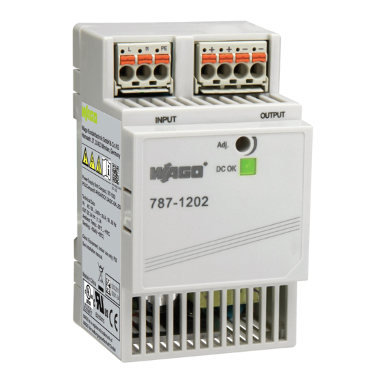
EPSITRON® COMPACT Power 787-1202 / -1212 / -1216 / -1226 EPSITRON® COMPACT Power Pos : 20 /All e Seri en (Allgemei ne Module)/Ü berschriften/N eue Ü berschriften/Ebene 2Ansicht - Ü bersc hrift 2 @ 4\mod_1240984217343_21.doc x @ 31958 @ 2 @ 1 View Pos : 21.1 /Serie 787 (EPSITRON)/Ger ätebesc hrei bung/Ansi cht/Ansic ht 787- 1202 @ 19\mod_1397554994715_21.doc x @ 151673 @ @ 1... -
Page 17: Figure 3: View 787-1216
EPSITRON® COMPACT Power Device Description 787-1202 / -1212 / -1216 / -1226 EPSITRON® COMPACT Power Figure 3: View 787-1216 Pos : 21.4 /Serie 787 (EPSITRON)/Ger ätebesc hrei bung/Ansi cht/Ansic ht 787- 1226 @ 19\mod_1397637459390_21.doc x @ 151797 @ @ 1 Figure 4: View 787-1226 Pos : 21.5 /Serie 787 (EPSITRON)/Ger ätebesc hrei bung/Ansi cht/Legende zur Abbil dung Ansic ht 787- 120x @ 19\mod_1397555012008_21.doc x @ 151681 @ @ 1... -
Page 18: Table 4: Legend For Figure "View
Device Description EPSITRON® COMPACT Power 787-1202 / -1212 / -1216 / -1226 EPSITRON® COMPACT Power Table 4: Legend for Figure “View” Pos. Description Details see section Screw mount clip “Mounting” > “Screw Mounting” Input “Device Description” > “Connections” Output “Device Description” > “Connections”... -
Page 19: Type Plate
Pos : 23 /Serie 787 (EPSITRON)/Ger ätebesc hrei bung/Ansicht/Ansic ht T ypensc hilder @ 19\mod_1400845453071_21.doc x @ 154713 @ 2 @ 1 Type Plate Die Geräte The device type plates 787-1202 / -1212 / -1216 / -1226 are located on the side of the housing: Figure 5: Type Plates... -
Page 20: Connectors
EPSITRON® COMPACT Power 787-1202 / -1212 / -1216 / -1226 EPSITRON® COMPACT Power Pos : 25 /All e Seri en (Allgemei ne Module)/Ü berschriften/N eue Ü berschriften/Ebene 2Anschl üss e - Ü berschrift 2 @ 4\mod_1240984262656_21.doc x @ 31961 @ 2 @ 1 Connectors Pos : 26.1 /All e Seri en ( Allgemei ne Module)/Sicherheits- und s ons tige Hi nweis e/Gefahr/Gefahr: Nic ht an Ger äten unter Spannung arbeiten! @ 6\mod_1260180365327_21.doc x @ 46727 @ @ 1... -
Page 21: Connector Input Side
EPSITRON® COMPACT Power Device Description 787-1202 / -1212 / -1216 / -1226 EPSITRON® COMPACT Power 3.3.1.1 Connector Input Side Figure 7: Connectors on the Input Side Table 6: Legend for Figure “Connectors on the Input Side” Pos. Description Connector “L” for input voltage Connector “N”... -
Page 22: Display Elements
EPSITRON® COMPACT Power 787-1202 / -1212 / -1216 / -1226 EPSITRON® COMPACT Power Pos : 28 /All e Seri en (Allgemei ne Module)/Ü berschriften/N eue Ü berschriften/Ebene 2Anzeigeel emente - Ü bers chrift 2 @ 4\mod_1240984390875_21.doc x @ 31964 @ 2 @ 1 Display Elements Pos : 29 /Serie 787 (EPSITRON)/Ger ätebesc hrei bung/Anzeigeelemente/Anz eigeelemente 787-12xx @ 19\mod_1397715825707_21.doc x @ 151948 @ @ 1... -
Page 23: Operating Elements
Device Description 787-1202 / -1212 / -1216 / -1226 EPSITRON® COMPACT Power Pos : 31 /All e Seri en (Allgemei ne Module)/Ü berschriften/N eue Ü berschriften/Ebene 2Bedi enelemente - Ü bersc hrift 2 @ 4\mod_1239191655456_21.doc x @ 30439 @ 2 @ 1 Operating Elements Pos : 32 /Serie 787 (EPSITRON)/Ger ätebesc hrei bung/Bedi enelemente/Bedienel emente 787- 12xx @ 19\mod_1397720125393_21.doc x @ 151978 @ 33 @ 1... -
Page 24: Technical Data
EPSITRON® COMPACT Power 787-1202 / -1212 / -1216 / -1226 EPSITRON® COMPACT Power Pos : 34 /All e Seri en (Allgemei ne Module)/Ü berschriften/N eue Ü berschriften/Ebene 2T ec hnis che D aten - Ü bersc hrift 2 @ 3\mod_1232967587687_21.doc x @ 26924 @ 2 @ 1 Technical Data Pos : 35.1 /Serie 787 (EPSITRON)/Ger ätebesc hrei bung/T ec hnisc he D aten/Angaben z um Ger ätGer ätedaten 787-12xx @ 19\mod_1397727762003_21.doc x @ 152055 @ @ 1... - Page 25 EPSITRON® COMPACT Power Device Description 787-1202 / -1212 / -1216 / -1226 EPSITRON® COMPACT Power Table 11: Electrical Data 787-1202 / 787-1212 787-1202 787-1212 Input Nominal input voltage U 100 VAC … 240 VAC 100 VAC … 240 VAC Input voltage range 85 VAC …...
-
Page 26: Table 11: Electrical Data 787-1202 / 787-1212
Device Description EPSITRON® COMPACT Power 787-1202 / -1212 / -1216 / -1226 EPSITRON® COMPACT Power Table 11: Electrical Data 787-1202 / 787-1212 787-1202 787-1212 Recommended external fuse Miniature circuit Miniature circuit breaker 6 A (C breaker 6 A (C characteristic), 10 A (B... - Page 27 EPSITRON® COMPACT Power Device Description 787-1202 / -1212 / -1216 / -1226 EPSITRON® COMPACT Power Table 12: Electrical Data 787-1216 / 787-1226 787-1216 787-1226 Input Nominal input voltage U 100 VAC … 240 VAC 100 VAC … 120 VAC 220 VAC … 240 VAC...
-
Page 28: Table 12: Electrical Data 787-1216 / 787-1226
Device Description EPSITRON® COMPACT Power 787-1202 / -1212 / -1216 / -1226 EPSITRON® COMPACT Power Table 12: Electrical Data 787-1216 / 787-1226 787-1216 787-1226 Recommended external fuse Miniature circuit Miniature circuit breaker 6 A (C breaker 6 A (C characteristic), 10 A (B... -
Page 29: Table 14: Environmental Conditions
EPSITRON® COMPACT Power Device Description 787-1202 / -1212 / -1216 / -1226 EPSITRON® COMPACT Power Table 14: Environmental Conditions Ambient operating temperature -25 °C … +70 °C Storage temperature -40 °C … +85 °C Relative humidity 10 % … 95 % Climatic category 3K3 (acc. -
Page 30: Approvals
Pos : 38.5 /Serie 787 (EPSITRON)/Ger ätebesc hrei bung/Z ulassungen/Z ulassungen 787- 12xx - Allgemein - in Vorberei tung - Ei nlei tung @ 19\mod_1397743118974_21.doc x @ 152190 @ @ 1 The following approvals are pending for the devices 787-1202 / -1212 / -1216 / - 1226: Pos : 38.6 /All e Seri en ( Allgemei ne Module)/Z ulassungen/Standardz ulassungen/cU Lus (U L508) @ 3\mod_1224055013140_0.doc x @ 24020 @ @ 1... -
Page 31: Standards And Guidelines
Pos : 41.1 /Serie 787 (EPSITRON)/Ger ätebesc hrei bung/N or men und Ric htli nien/N ormen 787-12xx - Ei nleitung @ 19\mod_1397741290216_21.doc x @ 152168 @ @ 1 The devices 787-1202 / -1212 / -1216 / -1226 comply with the following standards and directives: Pos : 41.2 /Serie 787 (EPSITRON)/Ger ätebesc hrei bung/N or men und Ric htli nien/N ormen 787-12xx - Mec hani k und Kli ma @ 19\mod_1397741370881_21.doc x @ 152171 @ @ 1... -
Page 32: Table 18: Emc - Immunity To Interference
Pos : 41.5 /Serie 787 (EPSITRON)/Ger ätebesc hrei bung/N or men und Ric htli nien/N ormen 787-12xx - Ei nleitung - EM V @ 19\mod_1397742075189_21.doc x @ 152174 @ @ 1 The devices 787-1202 / -1212 / -1216 / -1226 comply with the following EMC standards: Pos : 41.6 /Serie 787 (EPSITRON)/Ger ätebesc hrei bung/N or men und Ric htli nien/N ormen 787-12xx - Störfestig keit EMV @ 19\mod_1397742159386_21.doc x @ 152177 @ @ 1... -
Page 33: Other Information On Standards And Directives
EPSITRON® COMPACT Power Device Description 787-1202 / -1212 / -1216 / -1226 EPSITRON® COMPACT Power Table 19: EMC – Emission of Interference Standard Test value Emission – enclosure • EN 61004-3 Class B 40 dB(µV/m), QP, 30 MHz … 230 MHz 47 dB(µV/m), QP, 230 MHz …... -
Page 34: Mounting
EPSITRON® COMPACT Power 787-1202 / -1212 / -1216 / -1226 EPSITRON® COMPACT Power Pos : 44 /All e Seri en (Allgemei ne Module)/Ü berschriften/N eue Ü berschriften/Ebene 1M ontier en - Übersc hrift 1 @ 3\mod_1225446744750_21.doc x @ 24900 @ 1 @ 1 Mounting Pos : 45.1 /All e Seri en ( Allgemei ne Module)/Sicherheits- und s ons tige Hi nweis e/Ac htung/Achtung: Elektros tatisc he Entladung ver mei den! @ 6\mod_1260181364729_21.doc x @ 46759 @ @ 1... -
Page 35: Din 35 Rail
EPSITRON® COMPACT Power Mounting 787-1202 / -1212 / -1216 / -1226 EPSITRON® COMPACT Power Pos : 45.9 /Serie 787 (EPSITRON)/M ontier en/Montage 787- 12xx - Tr agschi ene @ 18\mod_1393403573026_21.doc x @ 146505 @ 233 @ 1 DIN 35 Rail The DIN-rail is centrally located relative to the depth of the device (see Section “Device Description”... -
Page 36: Removal From Din-Rail
Mounting EPSITRON® COMPACT Power 787-1202 / -1212 / -1216 / -1226 EPSITRON® COMPACT Power If the device does not lock into place automatically, pull down the DIN-rail mounting/removal latch with a screwdriver or operating tool while pressing the device onto the bottom fastener. -
Page 37: Screw Mounting
EPSITRON® COMPACT Power Mounting 787-1202 / -1212 / -1216 / -1226 EPSITRON® COMPACT Power Pos : 45.11 /Serie 787 ( EPSITR ON)/M onti eren/M ontag e 787-12xx - Sc hr aubbefestig ung @ 19\mod_1398413673375_21.doc x @ 152498 @ 2 @ 1 Screw Mounting Fastening clips are supplied with the device for screw mounting. - Page 38 Mounting EPSITRON® COMPACT Power 787-1202 / -1212 / -1216 / -1226 EPSITRON® COMPACT Power Gently shake the fastening clip to verify that it is fitted securely. Fasten the device with the appropriate M4 screws (not included). Observe the maximum torque of 2.9 Nm.
-
Page 39: Connect Devices
Connect Devices 787-1202 / -1212 / -1216 / -1226 EPSITRON® COMPACT Power Pos : 47 /All e Seri en (Allgemei ne Module)/Ü berschriften/N eue Ü berschriften/Ebene 1Ger äte anschli eßen - Ü berschrift 1 @ 3\mod_1234172889468_21.doc x @ 27460 @ 1 @ 1... -
Page 40: Connecting Using A Tool
® WAGO’s picoMAX pluggable connectors enable you to prewire devices to expedite device installation and avoid rewiring during device replacement. The procedure for removal and connection is the same for both WAGO plug connectors. ® WAGO picoMAX connectors consist of a male header (fixed in the device) and a female connector (pluggable). -
Page 41: Removing The Female Connector
EPSITRON® COMPACT Power Connect Devices 787-1202 / -1212 / -1216 / -1226 EPSITRON® COMPACT Power 5.1.2.2 Removing the Female Connector ® WAGO recommends using a picoMAX unlocking tool (referred to in the following text as the “unlocking tool”). Further information on the unlocking tool is provided in the Section “Accessories”... -
Page 42: 5.1.2.2.2 Removing The Female Connector With Wiring
Connect Devices EPSITRON® COMPACT Power 787-1202 / -1212 / -1216 / -1226 EPSITRON® COMPACT Power If you do not have an unlocking tool available, you can also remove the female connector with a WAGO operating tool or a screwdriver Do not insert the tool in the ventilation slots! Components inside the device may be damaged if the blade of an operating tool enters the ventilation slots. -
Page 43: Plugging In The Female Connector
EPSITRON® COMPACT Power Connect Devices 787-1202 / -1212 / -1216 / -1226 EPSITRON® COMPACT Power Do not pull on the cables when using a screwdriver or operating tool! When using a screwdriver or operating tool to remove the female connector do not pull on the cables! Grip underneath the protruding rim of the female connector to pull it out. -
Page 44: Notes On Operation
Pos : 54 /Serie 787 (EPSITRON)/In Betrieb nehmen/Betri ebs hinweis e 787-12xx - Frontplatte @ 19\mod_1399379693168_21.doc x @ 153108 @ 2 @ 1 Front Panel The 787-1202 / -1212 / -1216 / -1226 devices are provided with a front panel as a cover. This panel is removable depending on the device:... - Page 45 EPSITRON® COMPACT Power Notes on Operation 787-1202 / -1212 / -1216 / -1226 EPSITRON® COMPACT Power Ensure contact protection when used as a DIN-rail built-in installation device! When used as a DIN-rail built-in installation device according to DIN 43880 (domestic installation), the electrical installer must provide appropriate contact protection.
-
Page 46: Inrush Current
EPSITRON® COMPACT Power 787-1202 / -1212 / -1216 / -1226 EPSITRON® COMPACT Power Pos : 57 /All e Seri en (Allgemei ne Module)/Ü berschriften/N eue Ü berschriften/Ebene 2Einschalts trom - Ü berschrift 2 @ 19\mod_1399290468383_21.doc x @ 152971 @ 2 @ 1 Inrush Current Pos : 58 /Serie 787 (EPSITRON)/In Betrieb nehmen/Ei nsc hal tstrom 787-12xx @ 18\mod_1393416774771_21.doc x @ 146565 @ @ 1... -
Page 47: Parallel Connection (Output Side)
EPSITRON® COMPACT Power Notes on Operation 787-1202 / -1212 / -1216 / -1226 EPSITRON® COMPACT Power Pos : 60 /Serie 787 (EPSITRON)/In Betrieb nehmen/Parall elsc haltbetrieb ausgangss eitig 787-12xx @ 18\mod_1393416647820_21.doc x @ 146562 @ 2 @ 1 Parallel Connection (Output Side) In parallel operation, set the output voltage of the devices that will be connected in parallel as precisely as possible to the same value. -
Page 48: Short-Circuit And Overload Behavior
Pos : 62 /All e Seri en (Allgemei ne Module)/Ü berschriften/N eue Ü berschriften/Ebene 2Kurz schl uss- und Überlas tver hal ten - Ü berschrift 2 @ 19\mod_1399290715307_21.doc x @ 152977 @ 2 @ 1 Short-Circuit and Overload Behavior Pos : 63 /Serie 787 (EPSITRON)/In Betrieb nehmen/Kurzsc hluss- und Ü berl astverhalten 787-1202 @ 18\mod_1393416956002_21.doc x @ 146578 @ @ 1 The equipment's output is electronically protected from overload and short- circuits. -
Page 49: Table 27: Legend For Figure "Output Characteristic
EPSITRON® COMPACT Power Notes on Operation 787-1202 / -1212 / -1216 / -1226 EPSITRON® COMPACT Power Table 27: Legend for Figure “Output Characteristic” Pos. Description normal OUT(act) Overload mode (1.05 × I < I < 1.35 × I OUT(act) Constant power mode Short-circuit protection (1.40 ×... -
Page 50: Derating
EPSITRON® COMPACT Power 787-1202 / -1212 / -1216 / -1226 EPSITRON® COMPACT Power Pos : 65 /All e Seri en (Allgemei ne Module)/Ü berschriften/N eue Ü berschriften/Ebene 2D erating - Ü bers chrift 2 @ 19\mod_1399290806141_21.doc x @ 152983 @ 2 @ 1 Derating Pos : 66 /Serie 787 (EPSITRON)/In Betrieb nehmen/Der ati ng 787- 12xx @ 19\mod_1399295852460_21.doc x @ 153006 @ @ 1... -
Page 51: Maintenance
Repairs shall only occur within the scope of the measures outlined in these operating instructions. Should a fault occur, return the device to WAGO for repair. Provide the following information: •... -
Page 52: Accessories
EPSITRON® COMPACT Power 787-1202 / -1212 / -1216 / -1226 EPSITRON® COMPACT Power Pos : 73 /All e Seri en (Allgemei ne Module)/Ü berschriften/N eue Ü berschriften/Ebene 1Z ubehör - Übersc hrift 1 @ 5\mod_1252934119337_21.doc x @ 41582 @ 1 @ 1 Accessories Pos : 74 /Serie 787 (EPSITRON)/Z ubehör/Zubehör 787- xxxx Allgemeiner Ver weis auf Katal og und Internet @ 18\mod_1393418084887_21.doc x @ 146585 @ @ 1... -
Page 53: List Of Figures
Figure 13: Mounting the Device on DIN-Rail ............35 Figure 14: Removing the Device from DIN-Rail ..........36 Figure 15: Snap-fit Openings for Fastening Clips (787-1202 / 787-1212) ... 37 Figure 16: Snap-fit Openings for Fastening Clips (787-1216 / 787-1226) ... 37 Figure 17: Removing the Female Connector without Wiring (Application Example) ...................... -
Page 54: List Of Tables
EPSITRON® COMPACT Power 787-1202 / -1212 / -1216 / -1226 EPSITRON® COMPACT Power Pos : 80 /D okumentation allgemei n/Verz eic hniss e/Tabell enverz eichnis - Übersc hrift oG und Verz eichnis @ 3\mod_1219222958703_21.doc x @ 21084 @ @ 1 List of Tables Table 1: Item Numbers for DC Power Supplies ............ - Page 55 EPSITRON® COMPACT Power 787-1202 / -1212 / -1216 / -1226 EPSITRON® COMPACT Power Pos : 82 /D okumentation allgemei n/Einband/Einband H andbuc h - Leers eite für durc h 2 teilbar e Seitenzahl (Standar ddr uc k) @ 3\mod_1219230851078_0.doc x @ 21123 @ @ 1 Manual Version 1.0.0...
- Page 56 Pos : 83 /D okumentation allgemei n/Einband/Einband H andbuc h - R üc kseite 2015 @ 9\mod_1285229376516_21.doc x @ 64944 @ @ 1 WAGO Kontakttechnik GmbH & Co. KG Postfach 2880 • D-32385 Minden Hansastraße 27 • D-32423 Minden Phone: 05 71/8 87 –...
Need help?
Do you have a question about the 787-1202 and is the answer not in the manual?
Questions and answers