
Related Manuals for WAGO 787-1212


Summary of Contents for WAGO 787-1212
- Page 1 Power Supplies Switched-Mode Power Supply; Compact; 1-phase; Output voltage: 24 VDC; Output current: 2.5 A 0787-1212 Product manual | Version 1.0.0...
- Page 2 We wish to point out that the software and hardware terms as well as the trademarks of companies used and/or mentioned in the present manual are generally protected by trademark or patent. WAGO is a registered trademark of WAGO Verwaltungsgesellschaft mbH. Product manual | Version: 1.0.0 Compact Power Supply...
-
Page 3: Table Of Contents
0787-1212 Table of Contents Table of Contents Provisions......................... 5 Intended Use ...................... 5 Typographical Conventions.................. 6 Legal Information .................... 8 Security .......................... 9 General Safety Rules .................... 9 Requirements for Special Applications .............. 9 Electrical Safety..................... 10 Mechanical Safety .................... 10 Thermal Safety ...................... 11 Indirect Safety ....................... - Page 4 Table of Contents 0787-1212 Connection ........................ 27 Connectors ...................... 28 5.1.1 Conductor Termination ................. 28 5.1.2 WAGO picoMAX® Pluggable Connectors............ 28 5.1.2.1 Delivery Condition ................ 29 5.1.2.2 Pulling the Female Connector ............. 29 Operation ........................ 32 Setting the Output Voltage via Potentiometer ............ 32 Notes on Operation...................... 33...
-
Page 5: Provisions
0787-1212 Provisions Provisions This documentation applies to the WAGO Power Supplies Compact (787-1212). Note Observe the applicable documentation! This product must only be installed and operated according to the instructions of the com- plete Instructions for use. Knowledge of the complete Instructions for use is required for proper use. -
Page 6: Typographical Conventions
The terms set forth in the General Business & Contract Conditions for Delivery and Ser- vice of WAGO Kontakttechnik GmbH & Co. KG and the terms for software products and products with integrated software stated in the WAGO Software License Contract – both ü www.wago.com... - Page 7 0787-1212 Provisions ð This symbol identifies an intermediate result. ð This symbol identifies the result of an action. Lists • Lists, first level – Lists, second level Notes DANGER Type and source of hazard Possible consequences of hazard that also include death or irreversible injury •...
-
Page 8: Legal Information
Third-party products are always mentioned without any reference to patent rights. WAGO Kontakttechnik GmbH & Co. KG, or for third-party products, their manufacturer, retain all rights regarding patent, utility model or design registration. -
Page 9: Security
0787-1212 Security Security This section contains safety rules that must be followed for hazard-free use of the prod- uct. This section is aimed at the following target groups: • Planners and installers • Operators • Qualified assembly personnel • Qualified installation personnel (electrical installation, technician network installation etc.) •... -
Page 10: Electrical Safety
• Observe permissible temperature range of connecting cables. • Only clamp one conductor to each connection terminal. If several conductors must be clamped, wire them using an upstream wiring assembly (e.g., WAGO Through Termi- nal Blocks). • Use appropriate strain relief. -
Page 11: Thermal Safety
• The product contains no parts that can be serviced by the user. Always have all ser- vice, maintenance and repair work performed by specialists authorized by WAGO. • Observe the different technical specifications for mounting that does not correspond to the nominal mounting position. -
Page 12: Properties
Properties 3.1 Introduction The power supply units of the WAGO Power Supplies Compact Series are compact switched-mode power supplies with a wide range of uses. Their stepped design makes them suitable for applications, such as for use as a DIN rail built-in installation device in accordance with DIN 43880, and this is also supported by conformity with EN 60335-1. -
Page 13: Type Plate
8 DIN-35 Rail [} 24]. 3.3 Type Plate The type label for the product is attached to the side of the housing. It contains the follow- ing information: WAGO Kontakttechnik GmBH & Co.KG Hansastr.27, 32423 Minden, Germany www.wago.com ® EPSITRON COMPA CT Po w er... -
Page 14: Terminations - Input Side
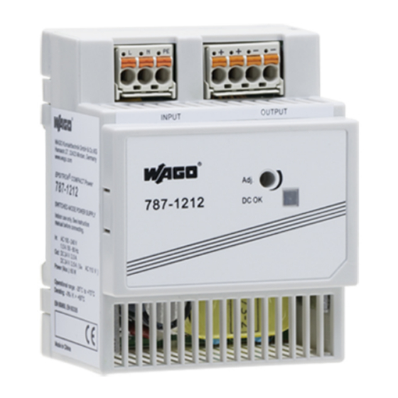
Properties 0787-1212 3.4.2 Terminations – Input Side Figure 3: Terminations – Input Side Table 4: Legend for the “Terminations – Input Side” Figure Position Description Termination “L” for input voltage Termination “N” for input voltage Termination “PE” for input voltage Integrated push-button Test slot 3.4.3 Terminations –... -
Page 15: Control Elements
0787-1212 Properties Figure 5: “DC OK” LED Table 6: Legend for “LED, DC OK” Figure Description State Explanation DC OK Green Switch-on threshold; output voltage > 22.5 VDC 3.6 Control elements This section describes the control elements. 8 Operation Instructions for using these control elements can be found in the Section [} 32]. -
Page 16: Input
Properties 0787-1212 29 mm – – – – DC OK 787 ! 1212 44 mm 9 mm 72 mm 56 mm Figure 7: Dimensions Table 8: Technical Data – Clearances Mounting Direc- Front side Clearance from tions Front Back Bottom Left Right Vertical Front... -
Page 17: Output
0787-1212 Properties Table 10: Technical Data – CC Input Property Value Nominal input voltage 140 … 340 VDC Input Voltage Range 125 … 375 VDC Input current (typ.) 140 VDC < 0.49 A 220 VDC < 0.31 A At nominal load Table 11: Technical Data – Inrush Current Property Value 1)2) - Page 18 Properties 0787-1212 Table 14: Technical Data – Output Property Value Load regulation ±1 % Residual ripple/noise < 100 mV (at 100 … 240 VAC) Overload behavior (1.05–1.35) × IOUT: Power limitation; shutdown in the event of a short circuit and permanent overload Short-circuit condition: Hiccup mode Switch-on delay...
-
Page 19: Efficiency/Power Loss
0787-1212 Properties Input Voltage Output Voltage Switch-on Time Figure 10: Turn-on Time NOTICE Select conductor cross-sections according to current load! In the event of a fault, the output current of a power supply can be up to 1.5 × I . Only use conductor cross-sections sufficient for the current load! Table 15: Technical Data –... -
Page 20: Mtbf/Lifespan
Properties 0787-1212 Output Current (A) Figure 11: Efficiency at 230 VAC Output Current (A) Figure 12: Power loss at 230 VAC 3.7.5 MTBF/Lifespan Table 17: Technical Data – MTBF/Lifespan Property Load Value MTBF (IEC 61709) 240 VAC 100 % 25 °C > 500000 h 3.7.6 Environment requirements Table 18: Technical Data ‒... -
Page 21: Product Protection
0787-1212 Properties Table 18: Technical Data ‒ Environmental Conditions Property Value Elevation above sea level, max. 2000 m (3000 m for storage) Overvoltage category Vibration according to IEC 60068-2-6 1g: < 9 Hz: 3.5 mm, 90 min, 2g: 9 < f < 150 Hz Shock according to IEC 60068-2-27 15g, 11 ms, 1000 shocks per axis and direction, half- sine... -
Page 22: Safety
CE Conformity Marking UL 508 UL 60950-1 Note More information on approvals You can find detailed information on the approvals online at: ü www.wago.com/<item number> 3.9 Standards The product meets the following standards: Table 22: Standards: Mechanical and Climatic Environmental Conditions... -
Page 23: Special Requirements
0787-1212 Properties Table 22: Standards: Mechanical and Climatic Environmental Conditions Standard Test Value Climatic Environmental Conditions EN 60870-2-2 3K3 (except for low air pressure) Table 23: Standards: EMC – Immunity to Interference Standard Title EN 61204-3 Low-Voltage Switch Mode Power Supplies – Part 3: Electromagnetic Com- patibility (EMC) EN 61000-4-2 Part 4-2: Testing and measurement techniques –... -
Page 24: Installation And Removal
When mounting with the front up or down, the following values must not be exceeded: Table 25: Values for Mounting Position – Mounting with Front Panel at Top or Bottom Product Output Power Surrounding air temperature 787-1212 50 % 55 °C The product can be mounted on a DIN-35 rail or with screws. Note Observe minimum clearances! 8 Technical... - Page 25 0787-1212 Installation and Removal Mounting on the DIN Rail Mount the product per EN 60715 by snapping it onto the DIN rail without any tools. Figure 15: Mounting the Product on the DIN rail 1. Tilt the product slightly. 2. Place the product, with its DIN rail guide, on the top edge of the DIN rail. 3.
-
Page 26: Screw Mount
Installation and Removal 0787-1212 2. Tilt the forward forward and unhook it from the DIN rail. 4.3 Screw Mount Two fastening clips are supplied with the product for screw mounting. Screw mounting is possible using these fastening clips. Figure 17: Snap-fit Openings for Fastening Clips – Top Figure 18: Snap-fit Openings for Fastening Clips –... -
Page 27: Connection
0787-1212 Connection Connection DANGER Do not work on products while energized! • Dangerous electrical voltage can lead to electric shock and burns. Disconnect all power sources to the product before performing any installation, re- pair or maintenance. DANGER Ensure a standard connection! •... -
Page 28: Connectors
4-pole: “L”, “N” and “PE” twice “+” and “-” 5.1.1 Conductor Termination WAGO's spring pressure connections are designed for solid or fine-stranded wires with and without ferrules. Note Connect only one conductor per connector! You must only connect one conductor to each spring clamp connection. Do not connect... -
Page 29: Delivery Condition
0787-1212 Connection The procedure for removal and connection is the same for both WAGO Pluggable Con- nectors. ® WAGO's picoMAX Pluggable Connectors consist of a male header (fixed in the product) and a female connector (pluggable). ® For more information on picoMAX , please visit “WAGO picoMAX®... - Page 30 4. Pull out the female connector. If you do not have an unlocking tool available, you can also remove the female connector with a WAGO operating tool or a screwdriver. WARNING Do not insert a tool into the ventilation slots! Components inside the device may be damaged if the blade of an operating tool enters the ventilation slots.
- Page 31 0787-1212 Connection NOTICE Do not pull on the cables when using a screwdriver or operating tool! When using a screwdriver or operating tool to remove the female connector do not pull on the cables! Grip underneath the protruding rim of the female connector to pull it out! Inserting the Female Connector DANGER ®...
-
Page 32: Operation
Operation 0787-1212 Operation 6.1 Setting the Output Voltage via Potentiometer The potentiometer [Adj.] can be used on the front of the product to set the output voltage between 20 … 27 VDC: • Turning counterclockwise increases the output voltage. • Turning clockwise decreases the output voltage. Product manual | Version: 1.0.0 Compact Power Supply... -
Page 33: Notes On Operation
Notes on Operation 7.1 Front panel The device WAGO Power Supplies Compact 787-1212 is provided with a front panel as a cover. This panel is removable. Only use the device as a DIN-rail built-in installation device with the front panel fitted per DIN 4388! -
Page 34: Short-Circuit And Overload Behavior
Notes on Operation 0787-1212 Restrictions (derating) apply when the power supply unit is used in applications that ex- ceed its performance specifications; these are listed below: Table 30: Deratings Nominal voltage Temperature value T Derating 90 ... 264 VAC > +55 °C −2.67 %/K < ... -
Page 35: Maintenance
Permitted repairs are limited to the measures listed in these operating instructions. Should a fault occur nonetheless, return the product to WAGO for repair. Provide the fol- lowing information: • Type of fault •... - Page 36 Notes on Operation 0787-1212 The convenient, standardized and therefore faster RMA process is available for returns and reports of defects. The corresponding report form for returns and reports of defects is available at ü https://www.wago.com/us/ruecksendungen-reklamationen. Product manual | Version: 1.0.0 Compact Power Supply...
-
Page 37: Decommissioning
0787-1212 Decommissioning Decommissioning 8.1 Disposal and Recycling Table 32: WEEE Mark Logo Description Electrical and electronic equipment may not be disposed of with household waste. This also applies to products without this mark. Electrical and electronic equipment contain materials and substances that can be harmful to the environment and health. -
Page 38: Appendix
Appendix 0787-1212 Appendix 9.1 Accessories Details on accessories are available online at ü www.wago.com. The following accessories are available for the product: Accessories – Communication Table 33: Accessories – Communication Description Designation Item Number Attachable communication module for I/O-Link Communication module IO-Link... -
Page 39: Protected Rights
0787-1212 Appendix Table 38: Accessories – Spare Parts Description Designation Item Number ® Female connector as spare part, output picoMAX 5.0, 4-pole 2092-1124/0000-9504 9.2 Protected Rights ® ® • Adobe and Acrobat are registered trademarks of Adobe Systems Inc. • Android is a trademark of Google LLC. - Page 40 List of Tables 0787-1212 List of Tables Table 1 Complete instructions for use .................... Table 2 Legend for “View” Figure ....................Table 3 Legend for Figure “Type Plate” ..................Table 4 Legend for the “Terminations – Input Side” Figure ............Table 5 Legend for the “Terminations –...
- Page 41 0787-1212 List of Tables Table 37 Accessories – Marking....................... Table 38 Accessories – Spare Parts....................Product manual | Version: 1.0.0 Compact Power Supply...
- Page 42 List of Figures 0787-1212 List of Figures Figure 1 View ..........................Figure 2 Type Plate ........................Figure 3 Terminations – Input Side ..................... Figure 4 Terminations – Output Side ..................Figure 5 “DC OK” LED ........................ Figure 6 Potentiometer........................ Figure 7 Dimensions ........................
- Page 43 0787-1212 List of Figures Product manual | Version: 1.0.0 Compact Power Supply...
- Page 44 WAGO is a registered trademark of WAGO Verwaltungsgesellschaft mbH. Copyright – WAGO Kontakttechnik GmbH & Co. KG – All rights reserved. The content and structure of the WAGO websites, catalogs, videos and other WAGO media are subject to copyright. Distribution or modification of the contents of these pages and videos is prohibited. Furthermore, the content may neither be copied nor made available to third parties for...
Need help?
Do you have a question about the 787-1212 and is the answer not in the manual?
Questions and answers