Table of Contents
Advertisement
Quick Links
deutsch /
english
Bedienungsanleitung /
Instruction Manual
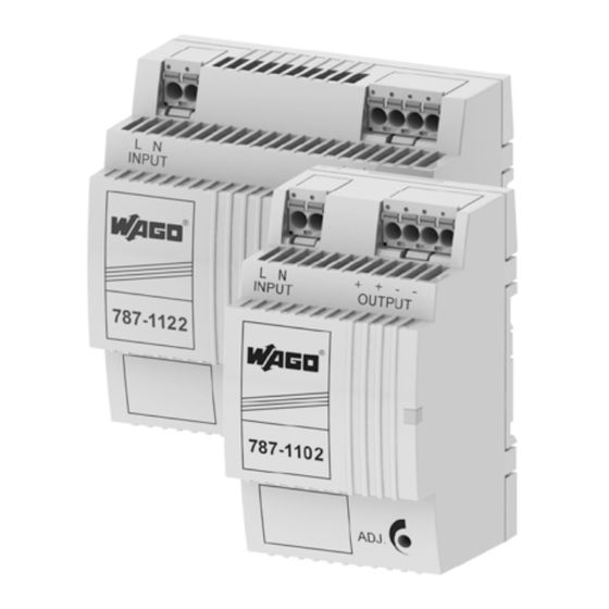
787-1102
EPSITRON
-Compact-Power
®
787-1112
Primärgetaktete Gleichstromversorgung
787-1122
Primary switched mode power supply
Anschluss
Connection
Abbildung zeigt den 787-1102
5
This figure shows the 787-1102
3
4
Eingang
Ausgang
+ –
+ + – –
6
1
2
U out
–
+
Installation
Installation
Sicherheitsmaßnahmen vor der Installation
Das Betriebsmittel ist vor unzulässiger Beanspruchung zu
schützen. Insbesondere dürfen bei Transport und Hand-
habung keine Bauelemente verbogen und/oder Isolations-
abstände verändert werden. Die Berührung elektrischer
Bauelemente und Kontakte ist zu vermeiden. Das Betriebs-
mittel immer im spannungsfreien Zustand montieren und
verdrahten. Die Produktbeschreibung und die technischen
Hinweise in unserem Hauptkatalog sowie die Aufschriften
am Betriebsmittel und auf dem Typenschild sind zu beachten.
Installation
Die Installation ist entsprechend den örtlichen Gege-
benheiten, einschlägigen Vorschriften (z. B. VDE 0100),
nationalen Unfallverhütungsvorschriften (z. B. UVV-VBG4
bzw. BGV A3) und den anerkannten Regeln der Technik
durchzuführen. Dieses elektrische Betriebsmittel ist eine
Komponente, die zum Einbau in elektrische Anlagen oder
Maschinen bestimmt ist und erfüllt die Anforderungen der
Niederspannungsrichtlinie (2014/35/EU). Der geforderte
Mindestabstand zu benachbarten Teilen ist einzuhalten, um
die Kühlung nicht zu behindern! Bei Einbau in Maschinen ist
die Aufnahme des bestimmungsgemäßen Betriebes solange
untersagt, bis festgestellt wurde, dass die Maschine den
Bestimmungen der Maschinenrichtlinie (2006/42/EG)
entspricht. EN 60204 ist zu beachten. Die Aufnahme des
bestimmungsgemäßen Betriebes ist nur bei Einhaltung der
EMV-Richtlinie (2014/30/EU) erlaubt. Die Einhaltung der
durch die EMV-Gesetzgebung geforderten Grenzwerte
liegt in der Verantwortung des Herstellers der Anlage oder
Maschine.
1
LED: Die grüne LED leuchtet, sofern
die Ausgangsspannung vorhanden ist.
2
Ausgangsspannung: Die Aus-
gangsspannung kann mit einem
Schraubendreher verändert werden.
Drehung im Uhrzeigersinn erhöht die
Ausgangsspannung. Drehung gegen
den Uhrzeigersinn verringert die
Ausgangsspannung.
3
Eingang
4
Ausgang
5
Montage: Setzen Sie das Gerät mit
der Tragschienenführung an die Ober-
kante der Tragschiene an und rasten
Sie es nach unten ein.
6
Demontage: Ziehen Sie den
Schnappriegel mit Hilfe eines
Schraubendrehers auf und hängen
Sie das Gerät an der Unterkante der
Tragschiene aus.
Safety measures before installation
This equipment is to be protected against improper use.
Components are not to be bent or isolation spacing changed,
especially through handling and transport. The contact with
electrical components and terminals is to be avoided. Always
disconnect the equipment from the mains supply, before
commencing installation or wiring. The product description,
technical information in our main catalogue and the marking
on the equipment ratings plate are to be observed.
Installation
Installation must be carried out according to the prevailing
local conditions and safety regulations (e.g. VDE 0100)
national accident prevention regulations (e.g. UVV-VBG4 or
BGV A3) and the generally accepted rules of technology. This
equipment is a component designed for installation into elec-
trical systems and machines, and fulfils the requirements of
the low voltage guidelines (2014/35/EU).
The required minimum spacing to neighbouring compon-
ents must be observed to guarantee the required cooling.
When installed into machinery, the normal operation is
forbidden until it is determined that the machine fulfils
the requirements of the machinery guidelines (2006/42/
EG). EN 60204 must be observed. The EMC requirements
(2014/30/EU) must be fulfilled before operation is com-
menced. The observance of the required limitations for the
EMC legislation is the responsibility of the manufacturer of
the installation or machinery.
1
LED: The green LED lights as soon as
the output voltage is present.
2
Output voltage: The output voltage
can be altered using a screwdriver.
Turning the adjustment screw clock-
wise raises the output voltage. Tur-
ning the adjustment screw anticlock-
wise reduce the output voltage.
3
Input
4
Output
5
Mounting: Place the device with the
DIN rail guide on the upper edge of the
DIN rail, and snap it in with a
downward motion.
6
Removing: Pull the snap lever open
with the aid of a screwdriver and slide
the device out at the lower edge of the
DIN rail.
Ausgangskennlinie (U/I Kennlinie)
Output characteristic (U/I Characteristic)
U
(V)
out
I
N
1,1 x I
N
I
(A)
out
Advertisement
Table of Contents

Subscribe to Our Youtube Channel
Related Manuals for WAGO EPSITRON-Compact-Power


Summary of Contents for WAGO EPSITRON-Compact-Power
- Page 1 Installation deutsch / english Installation Sicherheitsmaßnahmen vor der Installation Safety measures before installation Bedienungsanleitung / Instruction Manual Das Betriebsmittel ist vor unzulässiger Beanspruchung zu This equipment is to be protected against improper use. schützen. Insbesondere dürfen bei Transport und Hand- Components are not to be bent or isolation spacing changed, habung keine Bauelemente verbogen und/oder Isolations- especially through handling and transport.
- Page 2 +49 571-887-169 Anschlüsse Eingang (L, N) / Ausgang (+, +, -, -) *** info@wago.com WAGO picoMAX® eCOM 5.0 series 2092, max. 2,5 mm² Terminals input (L, N) / output (+, +, -, -) *** www.wago.com *** picoMAX nur im spannungslosen Zustand ziehen oder stecken. Zum * Für DC Eingangsspannung ist eine...
Need help?
Do you have a question about the EPSITRON-Compact-Power and is the answer not in the manual?
Questions and answers