
Subscribe to Our Youtube Channel
Related Manuals for WAGO Eco 2 Series


Summary of Contents for WAGO Eco 2 Series
- Page 1 Power Supplies Power Supply Eco 2; 1-phase, 24 VDC, 5 A, 120 W 2687-2144 | Version 1.0.0...
- Page 2 We wish to point out that the software and hardware terms as well as the trademarks of companies used and/or mentioned in the present manual are generally protected by trademark or patent. WAGO is a registered trademark of WAGO Verwaltungsgesellschaft mbH. | Version: 1.0.0 Power Supply Eco 2...
-
Page 3: Table Of Contents
2687-2144 Table of Contents Table of Contents Provisions ........................ 5 Intended Use ...................... 5 Typographical Conventions .................. 6 Legal Information ..................... 7 Safety .......................... 9 General Safety Rules .................... 9 Electrical Safety ....................... 9 Mechanical Safety .................... 9 Thermal Safety ...................... 10 Indirect Safety...................... - Page 4 Table of Contents 2687-2144 Connectors ...................... 28 Conductor Termination ................. 28 6.1.1 Operation ........................ 30 Setting the Output Voltage via Potentiometer ............ 30 Notes on Operation ....................... 31 Inrush Current...................... 31 Derating ......................... 31 Derating (Temperature-Dependent) ............. 31 8.2.1 Parallel Connection .................... 31 Short-Circuit and Overload Behavior ..............
-
Page 5: Provisions
1.1 Intended Use The WAGO Power Supply Eco 2 of the 2687 Series provides DC voltage to electrical or electronic devices, such as industrial control systems or display, communication and measuring devices. -
Page 6: Typographical Conventions
Provisions 2687-2144 Obligations of Installers/Operators The installers and operators bear responsibility for the safety of an installation or a sys- tem assembled with the products. The installer/operator is responsible for proper installa- tion and safety of the system. All laws, standards, guidelines, local regulations and ac- cepted technology standards and practices applicable at the time of installation, and the instructions in the the products’... - Page 7 1.3 Legal Information Intellectual property The intellectual property of this document belongs to WAGO GmbH & Co. KG. The repro- duction and distribution of its content (in whole or in part) is prohibited, unless otherwise provided by statutory provisions, written agreements or this document. In case of doubt, the written consent of WAGO GmbH &...
- Page 8 WAGO GmbH & Co. KG retains the right to carry out technical changes and improvements of the products and the data, specifications and illustrations of this manual.
-
Page 9: Safety
• Observe permissible temperature range of connecting cables. • Only clamp one conductor to each connection terminal. If several conductors must be clamped, wire them using an upstream wiring assembly (e.g., WAGO Through Termi- nal Blocks). • Use appropriate strain relief. -
Page 10: Thermal Safety
• The product contains no parts that can be serviced by the user. Always have all ser- vice, maintenance and repair work performed by specialists authorized by WAGO. • Observe possible different technical specifications for mounting that does not corre- spond to the specified mounting position. -
Page 11: Properties
Properties Properties 3.1 Overview The WAGO Power Supplies Eco 2 Series 2687 are switched mode Power supplies with a wide range of uses. They include all important basic functions and are available in differ- ent performance classes and widths. The Power supplies are fitted on a DIN-rail. With their slim design, they are suitable for use both in the control cabinet and in a compact distribution box. -
Page 12: View
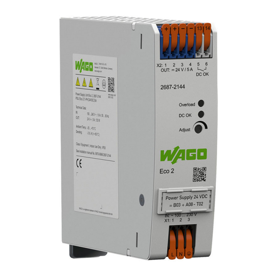
Properties 2687-2144 3.2 View Figure 1: View Pos. Comment Details Ventilation openings – Output X2 (+ − − 13 14) 8 Connections [} 14] Front side – Type label 8 Type label [} 13] LED indicator 8 Indicators [} 16] Potentiometer for setting the output voltage 8 Potentiometers [} 15] between 22 … 29 VDC QR code –... -
Page 13: Type Label
2687-2144 Properties Pos. Comment Details Marker carrier 8 Accessories [} 34] Input X1 (L N) 8 Connections [} 14] Latch for mounting to /removal from DIN rail – 3.3 Type label The product’s type plate contains the following information: | Version: 1.0.0 Power Supply Eco 2... -
Page 14: Connections
Label with product-specific information – 3.4 Connections 3.4.1 Terminal Blocks The supply lines are connected on the input and output side using the WAGO PCB termi- nal blocks with levers: • Input side: 3-pole • Output side: 6-pole Note the maximum permissible connection cross-sections of the power cables (see 8 Technical data... -
Page 15: Terminations - Output Side
2687-2144 Properties Position Description Termination “L” for input voltage Termination “N” for input voltage Termination “PE“ for ground conductor Lever 3.4.1.2 Terminations – Output Side Figure 3: Terminations – Output Side Position Description Termination 1 “+” for output voltage Termination 2 “+” for output voltage Termination 3 “−”... -
Page 16: Indicators
Properties 2687-2144 3.6 Indicators The indicators are located on the front of the product. The “DC OK” LED indicates the status of the output voltage U The “Overload” LED indicates the overload status. Figure 5: “Overload” LED and “DC OK” LED Description Status Explanation... -
Page 17: Input
2687-2144 Properties 138 mm 38 mm 131 mm 13 14 X2: 1 OUT: 24 V / 5 A DC OK 2687 2144 Overload DC OK Adjust Eco 2 Power Supply 24 VDC B03 + A08 - T03 IN: ~ 100 ... 240 V X1: 1 Figure 6: Dimensions Table 3: Technical Data –... -
Page 18: Output
Properties 2687-2144 Table 5: Technical Data – CC Input Property Value Nominal input voltage 90 … 300 VDC Input Voltage Range 90 … 300 VDC ( < 110 VDC derating required 1.5 %/V) Input current (typ.) 110 VDC < 1.30 A 220 VDC < 0.65 A 8 Accessories [ } An external DC fuse must be used with DC supply (see 34]). - Page 19 2687-2144 Properties Property Value Load regulation ±1 % Residual ripple/noise ≤ 75 mV (peak-to-peak, at 230 VAC) Overload behavior Constant power up to 125 % Shutdown and automatic restart in the event of a short circuit Switch-on delay 110 VAC < 1900 ms 230 VAC <...
-
Page 20: Efficiency/Power Loss
Properties 2687-2144 Input Voltage Output Voltage Switch-on Time Figure 9: Turn-on time Table 10: Technical Data – Output Side Connection Property Value Connection Technology 2604 Series (see 8 Appendix [} 34]) Cross-section Solid 0.2 … 4 mm² / 24 … 12 AWG Fine-stranded 0.2 … 4 mm² / 24 … 12 AWG Insulated ferrule with plastic collar 0.25 …... -
Page 21: Mtbf/Lifespan
2687-2144 Properties Figure 11: Power loss at 230 VAC 3.7.5 MTBF/Lifespan Table 12: Technical Data – MTBF/Lifespan Property Value MTBF (IEC 61709) 25 °C > 700000 h 3.7.6 Environment requirements Table 13: Technical Data – Environmental Conditions Property Value Ambient temperature, operation −25 … +70 °C (device starts at −40 °C, type- tested) 1) 2) Derating (Temperature-Dependent, >... -
Page 22: Product Protection
Properties 2687-2144 Load (%) Derating Curve -30 -20 -10 0 10 20 30 40 Surrounding Air Temperature (°C) Figure 12: Derating ambient temperature 3.7.7 Product Protection Table 14: Technical Data – Product Protection Property Value Internal input fuse T 3.15 A / 250 VAC Transient suppression at input Varistor Overload protection at output... -
Page 23: Approvals
2687-2144 Properties For additional information, visit ü www.wago.com. 3.8.2 Approvals The current approvals can be found on the product details page at: ü www.wago.com/. 3.8.3 Standards The product meets the following standards: Table 16: Standards: Mechanical and Climatic Environmental Conditions Standard Test Value... -
Page 24: Transport And Storage
Transport and Storage 2687-2144 Transport and Storage The original packaging offers optimal protection during transport and storage. • Store the product in suitable packaging, preferably the original packaging. • Only transport the product in suitable containers/packaging. • Make sure the product contacts are not contaminated or damaged during packing or unpacking. -
Page 25: Installation And Removal
2687-2144 Installation and Removal Installation and Removal The product can either be mounted on a DIN-35 rail or alternatively by means of a screw mount. 5.1 Mounting Positions and Clearances Table 20: Technical Data – Minimum Clearances Mounting Direc- Front Side Clearance from tions Front... - Page 26 Installation and Removal 2687-2144 Figure 14: Mounting the Product on the DIN rail 1. Tilt the product slightly. 2. Place the product, with its DIN rail guide, on the top edge of the DIN rail. 3. Press the product onto the DIN rail. 4.
- Page 27 2687-2144 Installation and Removal 2. Tilt the product forward and unhook it from the DIN rail. | Version: 1.0.0 Power Supply Eco 2...
-
Page 28: Connection
[} 34]). 6.1 Connectors 6.1.1 Conductor Termination WAGO's spring pressure connections are designed for solid or fine-stranded wires with and without ferrules. If more than one conductor must be routed to one connection, these must be connected in an up-circuit wiring assembly; for example, using WAGO Through Terminal Blocks. - Page 29 2687-2144 Connection Connecting by Opening the Connector Figure 16: Wiring by Opening the Lever The wiring requires no tools. Proceed as follows: 1. Open the connection of the corresponding conductor using the orange-colored lever [1]. 2. Insert the stripped conductor into the corresponding connection opening [2]. 3.
-
Page 30: Operation
Operation 2687-2144 Operation 7.1 Setting the Output Voltage via Potentiometer The potentiometer [Adj.] (see Control Elements) can be used on the front of the product to set the output voltage between 23 ... 28 VDC: • Turning clockwise increases the output voltage. •... -
Page 31: Notes On Operation
2687-2144 Notes on Operation Notes on Operation 8.1 Inrush Current If several products are connected in parallel and supplied on the input side using the same circuit, higher inrush currents can result. In this case, the use of auxiliary relays, which cause a time delay in startup, is recommended. -
Page 32: Short-Circuit And Overload Behavior
Notes on Operation 2687-2144 To decouple the outputs in parallel mode, a suitable redundancy module or diodes in the positive path are recommended. These diodes must be designed for the product’s maxi- mum output current. 8.4 Short-Circuit and Overload Behavior The product’s output is electronically protected against overload and short circuits. -
Page 33: Decommissioning
2687-2144 Decommissioning Decommissioning 9.1 Disposal and Recycling WEEE Mark Electrical and electronic equipment may not be disposed of with household waste. This also applies to products without this mark. Electrical and electronic equipment contain materials and substances that can be harmful to the environment and health. -
Page 34: Appendix
Appendix 2687-2144 Appendix 10.1 Accessories Details on accessories are available online at ü www.wago.com. The following accessories are available for the product: Accessories – Tools Table 23: Accessories – Tools Description Name Item Number Operating tool for setting the potentiometer Screwdriver PH0 210-769 Accessories –... - Page 35 2687-2144 Appendix ® • KNX is a registered trademark of the KNX Association cvba. ® • Linux is a registered trademark of Linus Torvalds. ® • LON is a registered trademark of the Echelon Corporation. ® • Modbus is a registered trademark of Schneider Electric, licensed for Modbus Organi- zation, Inc.
- Page 36 List of Tables 2687-2144 List of Tables Table 1 Terminal Blocks ......................... Table 2 Technical Data – Product....................Table 3 Technical Data – Clearances..................... Table 4 Technical Data – AC Input ....................Table 5 Technical Data – CC Input....................Table 6 Technical Data –...
- Page 37 2687-2144 List of Figures List of Figures Figure 1 View ..........................Figure 2 Terminations – Input Side ..................... Figure 3 Terminations – Output Side ..................Figure 4 Potentiometer ....................... Figure 5 “Overload” LED and “DC OK” LED ................Figure 6 Dimensions ........................
- Page 38 WAGO is a registered trademark of WAGO Verwaltungsgesellschaft mbH. Copyright – WAGO GmbH & Co. KG – All rights reserved. The content and structure of the WAGO websites, catalogs, videos and other WAGO media are subject to copyright. Distri- bution or modification of the contents of these pages and videos is prohibited. Furthermore, the content may neither be copied nor made available to third parties for commercial pur-...
Need help?
Do you have a question about the Eco 2 Series and is the answer not in the manual?
Questions and answers