WAGO Pro 2 Manual
Hide thumbs
Also See for Pro 2:
- Manual (68 pages) ,
- Product manual (68 pages) ,
- Product manual (78 pages)
Table of Contents
Advertisement
Quick Links
Advertisement
Chapters
Table of Contents

Related Manuals for WAGO Pro 2


Summary of Contents for WAGO Pro 2
- Page 1 Power Supplies Power Supply Pro 2 2787-2448 Product manual | Version 1.0.0...
- Page 2 We wish to point out that the software and hardware terms as well as the trademarks of companies used and/or mentioned in the present manual are generally protected by trademark or patent. WAGO is a registered trademark of WAGO Verwaltungsgesellschaft mbH. Product manual | Version: 1.0.0 Power Supply Pro 2...
-
Page 3: Table Of Contents
Product Protection .................. 23 3.9.10 Security ...................... 24 3.10 Guidelines, approvals and standards .............. 25 3.10.1 Guidelines .................... 25 3.10.2 Approvals ..................... 25 3.10.3 Standards ..................... 25 3.10.4 Special Requirements .................. 27 Product manual | Version: 1.0.0 Power Supply Pro 2... - Page 4 Diagnostics........................ 36 Diagnostics via Indicators.................. 36 Configuration........................ 37 Requirements ...................... 37 9.1.1 System Requirements .................. 37 9.1.2 Install WAGO Interface Configuration Software ........... 37 9.1.3 Configure Product .................. 37 First Steps ...................... 38 9.2.1 Starting the Software .................. 38 Overview ....................... 41 9.3.1...
- Page 5 “Top Boost” Mode.................. 59 10.7 Maintenance...................... 60 Decommissioning ...................... 61 11.1 Disposal and Recycling .................. 61 Appendix......................... 62 12.1 Application Notes .................... 62 12.1.1 AC Operation.................... 62 12.2 Accessories ...................... 63 12.3 Protected Rights.................... 64 Product manual | Version: 1.0.0 Power Supply Pro 2...
-
Page 6: Provisions
All the documentation is available at: ü www.wago.com. 1.1 Intended Use The 2787 Series WAGO Power Supply Pro 2 provides DC voltage to electrical or elec- tronic devices, such as industrial control systems or display, communication and measur- ing devices. -
Page 7: Typographical Conventions
The terms set forth in the General Business & Contractual Conditions apply to deliveries and services of WAGO Kontakttechnik GmbH & Co. KG, and the WAGO Software Li- cense Contract applies to software products and products with integrated software. Both are available at ü www.wago.com. - Page 8 Possible malfunctions that may restrict the product’s scope of functions or ergonomics, but do not lead to foreseeable risks to persons • Action step to reduce risk Note Notes and information Indicates information, clarifications, recommendations, referrals, etc. Product manual | Version: 1.0.0 Power Supply Pro 2...
-
Page 9: Legal Information
Third-party products are always mentioned without any reference to patent rights. WAGO Kontakttechnik GmbH & Co. KG, or for third-party products, their manufacturer, retain all rights regarding patent, utility model or design registration. -
Page 10: Security
• Only operate the product when the ground conductor is connected. • Protect the product with an appropriate overcurrent protection device. Conductors • Only use conductor cross-sections sufficient for the current load. • Observe permissible temperature range of connecting cables. Product manual | Version: 1.0.0 Power Supply Pro 2... -
Page 11: Mechanical Safety
2787-2448 Security • Only clamp one conductor to each connection terminal. If several conductors must be clamped, wire them using an upstream wiring assembly (e.g., WAGO Through Termi- nal Blocks). • Use appropriate strain relief. 2.3 Mechanical Safety • As the installer of the system, you are responsible for ensuring the necessary touch- proof protection. -
Page 12: Properties
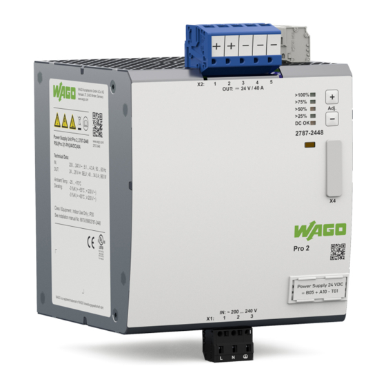
Properties 3.1 Introduction The 2787 Series WAGO Power Supplies Pro 2 are compact switched-mode Power Sup- plies with a wide range of uses. The Power Supplies can be fitted on a DIN-rail. The Power Supplies can be configured directly via buttons on the product or via the inte- grated communication interface. -
Page 13: Type Label
-3 %/K (> +55°C) Class I Equipment Indoor Use Only ; IP20 See installation manual No. 9970-0966/2787-2448 IND. CONT. EQ. WAGO is a registered trademark of WAGO Verwaltungsgesellschaft mbH. Figure 2: Type label Table 3: Legend for Figure “Type Plate” Position Comment... -
Page 14: Label
2D data matrix code Contains the information from positions 2 … 5 Key number Fixed information (37S) ID number per D-U-N-S® Fixed information (WAGO Minden) WAGO item number or internal SAP number Product-specific Consecutive number Product-specific Production date and revision • Production date •... -
Page 15: Input
Contact “−” for output voltage Contact “−” for output voltage Contact “+” for output voltage Contact “+” for output voltage Test slot Series 831 Series (see section 8 Accessories [} 63]) Connection technology Push-in CAGE CLAMP® Product manual | Version: 1.0.0 Power Supply Pro 2... -
Page 16: Signal
DC OK / Output Output Power Output Power Output Power Output Power Power < 25 % ≥ 25 % … < 50 % ≥ 50 % … < 75 % ≥ 75 % … ≥ 100 % < 100 % > 100 % Steady > 75 % Steady Steady > 50 % Steady Steady Steady Product manual | Version: 1.0.0 Power Supply Pro 2... -
Page 17: Control Elements
You can communicate with the product through the communication interface. The follow- ing options are available for this: • Via the WAGO USB Communication Cable (see section 8 Accessories [} 63]) 8 Accessories... -
Page 18: Technical Data
If you use a communication module, the corresponding communication module is de- & Product scribed in the Manual. To connect to a PC with the WAGO USB Communication Cable, perform the following steps: 1. Remove the cap. 2. Connect the USB connector of the WAGO USB Communication Cable to your PC. -
Page 19: Input
Value Nominal output voltage 24 VDC SELV Output voltage range 24 … 28 VDC SELV Nominal output current 40 A (see section 8 Derating [} 53]) Output current range 40 … 34.3 A Product manual | Version: 1.0.0 Power Supply Pro 2... -
Page 20: Table 20 Technical Data - Output Connection
1.5 s Factory setting Nominal load, in range 180 … 264 VAC 10 % / 90 % load step 20 MHz bandwidth 8 Short-Circuit and Overload Behavior [} 55] See section Can be set via the WAGO Interface Configuration software See figure “Turn-on Time” Input Voltage Overshoot Output Voltage Turn on Time Figure 10: Turn-on Time... -
Page 21: Efficiency/Power Loss
96.0 % Power loss (typ.) 200 VAC 42.5 W 240 VAC 39.4 W At nominal load At 230 VAC, the maximum efficiency of 96.3 % is achieved. Efficiency [%] Figure 11: Efficiency (typ.) at 240 VAC Product manual | Version: 1.0.0 Power Supply Pro 2... -
Page 22: Signal
0.25 … 1.5 mm² / 20 … 16 AWG Ferrule without plastic collar 0.25 … 2.5 mm² / 20 … 14 AWG Strip length 8 … 9 mm / 0.31 … 0.35 in Product manual | Version: 1.0.0 Power Supply Pro 2... -
Page 23: Communication
3.9.9 Product Protection Table 28: Technical Data – Product Protection Property Value Internal input fuse T 10 A / 250 VAC Transient suppression at input Yes, varistor Product manual | Version: 1.0.0 Power Supply Pro 2... -
Page 24: Security
Isolation voltage (output – digital input / output – digital out- 500 VAC put), ref. D Type test (rise 5 s – stay 2 s – fall 5 s); see figure “Dielectric Strength” Digital Output Digital Input Input Output Figure 13: Dielectric Strength Product manual | Version: 1.0.0 Power Supply Pro 2... -
Page 25: Guidelines, Approvals And Standards
UL 61010-1 Underwriters Laboratories UL 61010-2-201 Note More information on approvals You can find detailed information on the approvals online at: ü www.wago.com/<item number> 3.10.3 Standards The product meets the following standards: Table 32: Standards: Mechanical and Climatic Environmental Conditions Standard... -
Page 26: Table 34 Standards: Emc - Emission Of Interference
0.15 … 80 MHz: digital input/ 20 V digital output Communication 0.15 … 80 MHz: 20 V EN 61000-4-8 Part 4-8: Testing and measurement 50/60 Hz 300 A/m techniques – Power frequency mag- netic field immunity test Product manual | Version: 1.0.0 Power Supply Pro 2... -
Page 27: Special Requirements
Machinery Directive, EN 60204. • Commencement of normal operation is allowed only on the condition of compliance with the EMC Directive. Product manual | Version: 1.0.0 Power Supply Pro 2... - Page 28 Properties 2787-2448 • The manufacturer of the system or machine is responsible for ensuring compliance with the limit values required by EMC legislation. Product manual | Version: 1.0.0 Power Supply Pro 2...
-
Page 29: Functions
Configurable load management For details, see section 8 Dialog:Settings [} 42]. Communication interface Allows connection via a WAGO USB Communication Cable (see 8 Communication Interface section [} 17]) or via a communica- tion module that is available as an option. The communication modules allow configuration and monitoring of the product via fieldbus systems. -
Page 30: Installation And Removal
(adjacent device generates additional heat; equivalent product un- der full load) DIN-35 Rail The DIN-35 rail is located in the center of the vertical axis (height) of the product (see 8 Technical Data section [} 18]). Product manual | Version: 1.0.0 Power Supply Pro 2... -
Page 31: Figure 14 Position Of The Din-35 Rail
2. Press the product onto the DIN-35 rail [A] while simultaneously pulling on the latch (k) on [B] until it locks into place. 3. To ensure secure fastening on the DIN-35 rail, fit end stops on either side of the product (e.g., order no. 249-197). Product manual | Version: 1.0.0 Power Supply Pro 2... -
Page 32: Figure 16 Removal
1. To remove (see figure “Removal”), pull the latch (k) down [C], using a screwdriver or an operating tool. 2. Pivot the product to remove it from the DIN-35 rail [D]. Product manual | Version: 1.0.0 Power Supply Pro 2... -
Page 33: Connection
If more than one conductor must be routed to one connection, these must be connected in an up-circuit wiring assembly, for example, using WAGO Through Terminal Blocks. To connect the conductors, use an operating tool (see section 8 Accessories... -
Page 34: Push-In Termination
• Fine-stranded conductors with ferrules and plastic collars for all permissible cross-sec- tions • Fine-stranded conductors with ferrules without plastic collars with a cross-section > 0.5 mm²/AWG 20 • Solid conductors with a cross-section > 0.5 mm²/AWG 20 Product manual | Version: 1.0.0 Power Supply Pro 2... -
Page 35: Operation
During ongoing operation, you can set the output voltage and reset the product to the fac- tory settings. These settings can be saved and then remain available when the product is switched off and back on. Product manual | Version: 1.0.0 Power Supply Pro 2... -
Page 36: Diagnostics
Shutdown Fault face > 100 % Flashing (8 Hz) Flashing (8 Hz) Flashing (8 Hz) Flashing (8 Hz) > 75 % Steady Flashing (8 Hz) > 50 % Flashing (8 Hz) > 25 % Flashing (8 Hz) DC OK Flashing (8 Hz) Steady Automatic restart (factory setting) Product manual | Version: 1.0.0 Power Supply Pro 2... -
Page 37: Configuration
2787-2448 Configuration Configuration 9.1 Requirements 9.1.1 System Requirements The following system requirements must be met for the WAGO Interface Configuration software to be installed: Minimum System Requirements Table 43: Minimum System Requirements Components Requirements Operating system • Windows 7 (32- and 64-bit) •... -
Page 38: First Steps
Configuration 2787-2448 The following requirements must be met before you can work online with the WAGO In- terface Configuration software: • The product must be connected to the computer on which the WAGO Interface Config- uration software is installed. • The product must be supplied with power. -
Page 39: Backstage" Tab
On this tab, you can make the following settings: 1. Select the Communication menu item. 2. In the “Communication Settings” dialog, under COM port, select the corresponding entry for your connection between the computer and the product (example: WAGO USB service cable). Product manual | Version: 1.0.0... -
Page 40: Device" Tab
Connect menu item. The software automatically detects which product is connected. Your product is connected to the software. You can now use the software to address, configure and evaluate your product. Product manual | Version: 1.0.0 Power Supply Pro 2... -
Page 41: Table 48 Legend For The "Graphical User Interface" Overview
You can find more information in section 8 Display Section [} 49]. Product Information This section contains information on the connected product. Footer The footer indicates the status and interface of the active connec- tion. Product manual | Version: 1.0.0 Power Supply Pro 2... -
Page 42: Dialog: Settings
Update Performs a firmware update on the product. You can get the current firmware update and corre- sponding compatibility information from WAGO Tech- nical Support. 9.3.1.2.1 Dialog: Settings In this dialog, you can modify settings for the product. Two options are available: •... -
Page 43: Table 50 Dialog: Settings - Buttons
Writes all the settings that have been made to the connected product. [Close] Closes the dialog. Any settings that have not been saved are lost. The individual sections of the dialog are described below. DC Output Figure 26: Dialog: Settings – DC Output Product manual | Version: 1.0.0 Power Supply Pro 2... -
Page 44: Table 51 Dialog: Settings - Dc Output
If this box is checked, the “Top Boost” overload behav- ior is enabled. The power supply provides up to 500 % more output power for 15 s. You can find more infor- 8 Top Boost mation in section [} 59]. Product manual | Version: 1.0.0 Power Supply Pro 2... -
Page 45: Table 52 Dialog: Settings - Signalization
0 to 1. Function triggered by high- If this box is checked, the digital input is activated in low transition the event of an edge change from 1 to 0. Product manual | Version: 1.0.0 Power Supply Pro 2... -
Page 46: Figure 28 Dialog: Settings - System
Here you can enter the value for current (unit: mA) at or above which a warning message is generated. These parameters are not mutually exclusive and can also be selected simultaneously. System Figure 28: Dialog: Settings – System Product manual | Version: 1.0.0 Power Supply Pro 2... -
Page 47: Table 53 Dialog: Settings - System
All the input fields can be freely edited. You Function name can enter up to 32 characters into each input field. Customer information These parameters are mutually exclusive and can only be selected individually. Product manual | Version: 1.0.0 Power Supply Pro 2... -
Page 48: Table 54 Dialog: Settings - Password
You can enter the password here. The password can consist of at most eight characters (from the ASCII character set). Show password If this box is checked, the password entered is shown without encryption. Product manual | Version: 1.0.0 Power Supply Pro 2... -
Page 49: Main Menu
The Display section differs according to the menu item selected in the main menu. 9.3.3.1 Display Section: Measurements Figure 31: Display Section: “Measurements” This Display section shows the current operating states, warnings and errors: Product manual | Version: 1.0.0 Power Supply Pro 2... -
Page 50: Table 56 Display Section: "Measurements
Errors Overheating, device switched Green indicator: Status OK Red indicator: Error present No output voltage Output short circuit When Power Boost or Top Boost is output, this is signaled for 5 s. Product manual | Version: 1.0.0 Power Supply Pro 2... -
Page 51: Display Section: Measurement Recording
[Start] Starts the recording (setting at pos. 1 = chart). [Stop] Stops the recording before the specified number is reached (setting at pos. 1 = chart). Product manual | Version: 1.0.0 Power Supply Pro 2... -
Page 52: Display Section: Information
This shows the order number of the product. Description: This shows the manufacturer’s name for the product. SW-Version: This shows the current release of the software version (firmware). HW-Version: This shows the current release of the hardware version. Product manual | Version: 1.0.0 Power Supply Pro 2... -
Page 53: Notes On Operation
10.3 Inrush Current High inrush currents can occur if multiple products are supplied through the same circuit on the input side. In this case, it is advisable to switch the WAGO Power Supply Pro 2 on 8 Dialog: with a delay. The corresponding switch-on delay can be parameterized in the Settings [} 42]... -
Page 54: Derating (Temperature-Dependent)
Depending on the installation altitude and the surrounding air temperature, it may be nec- essary to reduce the load. Table 61: Derating (Location-Dependent) Temperature Value Derating > +50 °C −8.9 %/1000 m (> +50 °C; 3600 m or higher) > +55 °C −8.6 %/1000 m (> +55 °C; 2100 m or higher) Product manual | Version: 1.0.0 Power Supply Pro 2... -
Page 55: Parallel Connection
8 Dialog: Settings [} 42] power supplies. This setting can be enabled in the dialog in the “DC Output” section of the WAGO Interface Configuration software. 10.6 Short-Circuit and Overload Behavior The product’s output is electronically protected against overload and short circuits. -
Page 56: Constant Current" Mode
If the overload lasts longer, the output is switched off. To switch the output back on, man- ual intervention is necessary. The following options are available for this: • Communication interface • Buttons • Digital input Product manual | Version: 1.0.0 Power Supply Pro 2... -
Page 57: Hiccup" Mode
To switch the output back on, manual interven- tion is necessary. The following options are available for this: • Communication interface • Buttons Product manual | Version: 1.0.0 Power Supply Pro 2... -
Page 58: Latching Shutdown On Thermal Overload" Mode
10.6.5 “Latching Shutdown on Thermal Overload” Mode In this mode, the output voltage is switched off in the event of excessive internal device temperature. A corresponding “High Device Temperature” warning can, for example, be 8 WAGO Interface Configuration software [} 42] transmitted via the or passed to a 8 communication module... -
Page 59: Top Boost" Mode
In addition, calculate the error loop impedance. The maximum current that can flow through the error loop (due to the impedance) must not be lower than trip current of the overcurrent protection device necessary to reliably trip it. Product manual | Version: 1.0.0 Power Supply Pro 2... -
Page 60: Maintenance
Permitted repairs are limited to the measures listed in these operating instructions. Should a fault occur nonetheless, return the product to WAGO for repair. Provide the fol- lowing information: • Type of fault •... -
Page 61: Decommissioning
• Have electrical and electronic equipment sent to a local collection point. • The guidelines 2006/66/EG, PPWD 2018/852/EU and WEEE 2012/19/EU apply throughout Europe. National directives and laws may vary. Product manual | Version: 1.0.0 Power Supply Pro 2... -
Page 62: Appendix
Appendix 2787-2448 Appendix 12.1 Application Notes The following figures illustrate examples of how a WAGO Power Supply Pro 2 can be connected as a consumer in three different grounding systems: TN, TT and IT. 12.1.1 AC Operation Source (AC); 1-phase Load Figure 42: AC input... -
Page 63: Accessories
Attachable IO-Link Communication Module for IO-Link Communication Module 2789-9080 WAGO Power Supply Pro 2 Attachable Modbus RTU® Communication Modbus RTU® Communication 2789-9015 Module for WAGO Power Supply Pro 2 Module WAGO USB Communication Cable 2.5 m 0750-0923 Accessories – Tools Table 64: Accessories – Tools... -
Page 64: Protected Rights
• QR Code is a registered trademark of DENSO WAVE INCORPORATED. ® • Subversion is a trademark of the Apache Software Foundation. ® • Windows is a registered trademark of Microsoft Corporation. Product manual | Version: 1.0.0 Power Supply Pro 2... - Page 65 Table 34 Standards: EMC – Emission of Interference..............Table 35 Standards: EMC – Immunity to Interference (Tests Performed)........Table 36 Legend for “Standards: EMC – Immunity to Interference (Tests Performed)” ....Product manual | Version: 1.0.0 Power Supply Pro 2...
- Page 66 Derating (Temperature-Dependent)................... Table 61 Derating (Location-Dependent)..................Table 62 WEEE Mark ........................Table 63 Accessories – Communication................... Table 64 Accessories – Tools......................Table 65 Accessories – Marking....................... Table 66 Accessories – Spare Parts....................Product manual | Version: 1.0.0 Power Supply Pro 2...
- Page 67 Display Section: “Measurements” ................. Figure 32 Display Section: “Measurement Recording” ..............Figure 33 Display Section: Information ..................Figure 34 Derating (Temperature-Dependent)................Figure 35 Derating (Location-Dependent)..................Figure 36 “Constant Current” Mode ....................Product manual | Version: 1.0.0 Power Supply Pro 2...
- Page 68 “Power Boost” Mode in Combination with “Constant Current” Mode ......Figure 41 Loop Impedance ......................Figure 42 AC input ........................Figure 43 TN Network ........................Figure 44 TT Network........................Figure 45 IT Network........................Product manual | Version: 1.0.0 Power Supply Pro 2...
- Page 69 2787-2448 List of Figures Product manual | Version: 1.0.0 Power Supply Pro 2...
- Page 70 WAGO is a registered trademark of WAGO Verwaltungsgesellschaft mbH. Copyright – WAGO Kontakttechnik GmbH & Co. KG – All rights reserved. The content and structure of the WAGO websites, catalogs, videos and other WAGO media are subject to copyright. Distribution or modification of the contents of these pages and videos is prohibited. Furthermore, the content may neither be copied nor made available to third parties for...
Need help?
Do you have a question about the Pro 2 and is the answer not in the manual?
Questions and answers