Table of Contents
Advertisement
Quick Links
LOV TO ELECTRIC S.P. .
24020 GORLE (BERGAMO) ITALIA
VIA DON E. MAZZA, 12
TEL. 035 4282111
L
E
E-mail info@
ovato
lectric.com
L
E
Web
www.
ovato
lectric.com
UE declarations: http://www.lovatoelectric.com/DMED311MID7/DMED311MID7/snp,
http://www.lovatoelectric.com/DMED341MID7/DMED341MID7/snp,
http://www.lovatoelectric.com/DMED341MID7E/DMED341MID7E/snp and
http://www.lovatoelectric.com/DMED341MID7ER/DMED341MID7ER/snp
W RNING!
– Carefully read the manual before the installation or use.
– This equipment is to be installed by qualified personnel, complying to current standards, to avoid
damages or safety hazards.
– Before any maintenance operation on the device, remove all the voltages from measuring and supply inputs and short-
circuit the CT input terminals.
– The manufacturer cannot be held responsible for electrical safety in case of improper use of the equipment.
– Products illustrated herein are subject to alteration and changes without prior notice. Technical data and descriptions
in the documentation are accurate, to the best of our knowledge, but no liabilities for errors, omissions or
contingencies arising there from are accepted.
– A circuit breaker must be included in the electrical installation of the building. It must be installed close by the
equipment and within easy reach of the operator. It must be marked as the disconnecting device of the equipment:
IEC/EN/BS 61010-1 § 6.11.3.1.
– Clean the device with a soft dry cloth; do not use abrasives, liquid detergents or solvents.
TTENTION !
– Lire attentivement le manuel avant toute utilisation et installation.
– Ces appareils doivent être installés par un personnel qualifié, conformément aux normes en vigueur en
matière d'installations, afin d'éviter de causer des dommages à des personnes ou choses.
– Avant toute intervention sur l'instrument, mettre les entrées de mesure et d'alimentation hors tension et court-circuiter
les transformateurs de courant.
– Le constructeur n'assume aucune responsabilité quant à la sécurité électrique en cas d'utilisation impropre du
dispositif.
– Les produits décrits dans ce document sont susceptibles d'évoluer ou de subir des modifications à n'importe quel
moment. Les descriptions et caractéristiques techniques du catalogue ne peuvent donc avoir aucune valeur
contractuelle.
– Un interrupteur ou disjoncteur doit être inclus dans l'installation électrique du bâtiment. Celui-ci doit se trouver tout
près de l'appareil et l'opérateur doit pouvoir y accéder facilement. Il doit être marqué comme le dispositif
d'interruption de l'appareil : IEC/EN/BS 61010-1 § 6.11.3.1.
– Nettoyer l'appareil avec un chiffon doux, ne pas utiliser de produits abrasifs, détergents liquides ou solvants.
CHTUNG!
– Dieses Handbuch vor Gebrauch und Installation aufmerksam lesen.
– Zur Vermeidung von Personen- und Sachschäden dürfen diese Geräte nur von qualifiziertem
Fachpersonal und unter Befolgung der einschlägigen Vorschriften installiert werden.
– Vor jedem Eingriff am Instrument die Spannungszufuhr zu den Messeingängen trennen und die Stromwandler
kurzschlieβen.
– Bei zweckwidrigem Gebrauch der Vorrichtung übernimmt der Hersteller keine Haftung für die elektrische Sicherheit.
– Die in dieser Broschüre beschriebenen Produkte können jederzeit weiterentwickelt und geändert werden. Die im
Katalog enthaltenen Beschreibungen und Daten sind daher unverbindlich und ohne Gewähr.
– In die elektrische Anlage des Gebäudes ist ein Ausschalter oder Trennschalter einzubauen. Dieser muss sich in
unmittelbarer Nähe des Geräts befinden und vom Bediener leicht zugänglich sein. Er muss als Trennvorrichtung für das
Gerät gekennzeichnet sein: IEC/EN/BS 61010-1 § 6.11.3.1.
– Das Gerät mit einem weichen Tuch reinigen, keine Scheuermittel, Flüssigreiniger oder Lösungsmittel verwenden.
DVERTENCI
– Leer atentamente el manual antes de instalar y utilizar el regulador.
– Este dispositivo debe ser instalado por personal cualificado conforme a la normativa de instalación
vigente a fin de evitar daños personales o materiales.
– Antes de realizar cualquier operación en el dispositivo, desconectar la tensión de las entradas de alimentación y
medida, y cortocircuitar los transformadores de corriente.
– El fabricante no se responsabilizará de la seguridad eléctrica en caso de que el dispositivo no se utilice de forma
adecuada.
– Los productos descritos en este documento se pueden actualizar o modificar en cualquier momento. Por consiguiente,
las descripciones y los datos técnicos aquí contenidos no tienen valor contractual.
– La instalación eléctrica del edificio debe disponer de un interruptor o disyuntor. Éste debe encontrarse cerca del
dispositivo, en un lugar al que el usuario pueda acceder con facilidad. Además, debe llevar el mismo marcado que el
interruptor del dispositivo (IEC/EN/BS 61010-1 § 6.11.3.1).
– Limpiar el dispositivo con un trapo suave; no utilizar productos abrasivos, detergentes líquidos ni disolventes.
UPOZORNĚNÍ
AVERTIZARE!
GB
THREE-PH SE DIRECT CONNECTION ENERGY METER WITH
BUILT-IN RS485
Instruction manual
I
CONT TORE DI ENERGI TRIF SE INSERZIONE DIRETT CON
RS485 INTEGR T
Manuale operativo
DMED311MID7 - DMED341MID7 -
DMED341MID7E - DMED341MID7ER
Dichiarazione UE: http://www.lovatoelectric.com/DMED311MID7/DMED311MID7/snp,
http://www.lovatoelectric.com/DMED341MID7/DMED341MID7/snp,
http://www.lovatoelectric.com/DMED341MID7E/DMED341MID7E/snp e
http://www.lovatoelectric.com/DMED341MID7ER/DMED341MID7ER/snp
TTENZIONE!
– Leggere attentamente il manuale prima dell'utilizzo e l'installazione.
– Questi apparecchi devono essere installati da personale qualificato, nel rispetto delle vigenti normative
impiantistiche, allo scopo di evitare danni a persone o cose.
– Prima di qualsiasi intervento sullo strumento, togliere tensione dagli ingressi di misura e di alimentazione e
cortocircuitare i trasformatori di corrente.
– Il costruttore non si assume responsabilità in merito alla sicurezza elettrica in caso di utilizzo improprio del dispositivo.
– I prodotti descritti in questo documento sono suscettibili in qualsiasi momento di evoluzioni o di modifiche. Le
descrizioni ed i dati a catalogo non possono pertanto avere alcun valore contrattuale.
– Un interruttore o disgiuntore va compreso nell'impianto elettrico dell'edificio. Esso deve trovarsi in stretta vicinanza
dell'apparecchio ed essere facilmente raggiungibile da parte dell'operatore. Deve essere marchiato come il dispositivo
di interruzione dell'apparecchio: IEC/EN/BS 61010-1 § 6.11.3.1.
– Pulire l'apparecchio con panno morbido, non usare prodotti abrasivi, detergenti liquidi o solventi.
UW G !
ПРЕДУПРЕЖДЕНИЕ!
DİKKAT!
UPOZORENJE!
1
Advertisement
Table of Contents

Related Manuals for LOVATO ELECTRIC DMED311MID7


Summary of Contents for LOVATO ELECTRIC DMED311MID7
- Page 1 LOV TO ELECTRIC S.P. . RS485 INTEGR T 24020 GORLE (BERGAMO) ITALIA VIA DON E. MAZZA, 12 Manuale operativo TEL. 035 4282111 E-mail info@ ovato lectric.com DMED311MID7 - DMED341MID7 - www. ovato lectric.com DMED341MID7E - DMED341MID7ER UE declarations: http://www.lovatoelectric.com/DMED311MID7/DMED311MID7/snp, Dichiarazione UE: http://www.lovatoelectric.com/DMED311MID7/DMED311MID7/snp, http://www.lovatoelectric.com/DMED341MID7/DMED341MID7/snp, http://www.lovatoelectric.com/DMED341MID7/DMED341MID7/snp, http://www.lovatoelectric.com/DMED341MID7E/DMED341MID7E/snp and...
-
Page 2: Table Of Contents
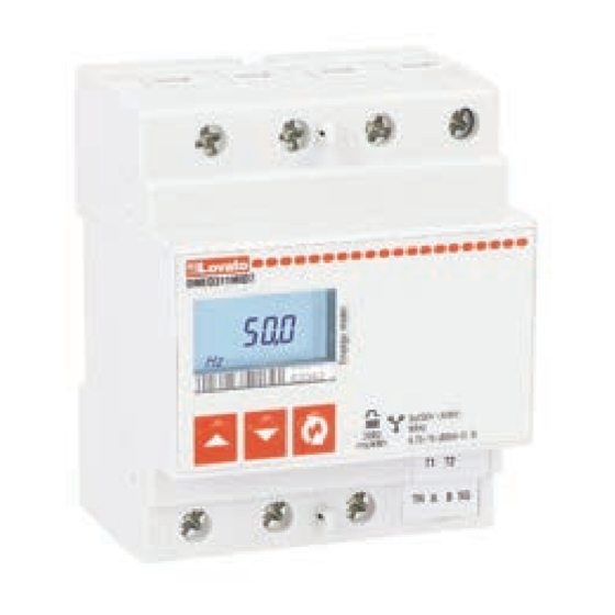
INTRODUZIONE The DMED311MID7 and the DMED341MID7... are a three-phase energy meters for direct connection, for Il DMED311MID7 e i DMED341MID7... sono dei contatori di energia trifase per inserzione diretta, per currents up to 80A with built-in RS485 – Modbus interface. -
Page 3: Selection Of Readings
The tariff presently selected by the external input is indicated by the flashing T1 or T2 icon tariffa. La tariffa attualmente selezionata è indicata dall’icona T1 o T2 lampeggianti (DMED311MID7 only). (solo DMED311MID7). ∑ The character “I” is shown at display in case of inductive value, character “C” in case of ∑... -
Page 4: Advanced Functions
6 cifre. Please contact LOVATO Electric Technical support reporting this unlock code. The right password will be Contattare l’Assistenza tecnica LOVATO Electric comunicando il codice di sblocco. Verrà restituita la provided. -
Page 5: Setup Parameters Table (Dmed311Mid7)
SETUP PARAMETERS TABLE TABELLA PARAMETRI DI SETUP (DMED311MID7) (DMED311MID7) Code Description Default Range Codice Descrizione Default Range P1.01 Password 0000 0000 - 9999 P1.01 Password 0000 0000 - 9999 Exported energies viewing enable OFF-ON Visualizzazione energie esportate OFF-ON P1.02 P1.02 P2.01... -
Page 6: Ac Programmable Input
– The DMED311MID7 has a programmable AC input, with programmable function. – Il DMED311MID7 dispone di un ingresso in AC, con funzione programmabile. – By default, this input is disabled. Set parameter P5.01 in order to choose the required function. -
Page 7: Setup Parameters Table (Dmed341Mid7
SETUP PARAMETERS TABLE TABELLA PARAMETRI DI SETUP (DMED341MID7...) (DMED341MID7...) Code Description Default Range Codice Descrizione Default Range P1.01 Password 0000 0000 - 9999 P1.01 Password 0000 0000 - 9999 Exported energies viewing enable OFF-ON Visualizzazione energie esportate OFF-ON P1.02 P1.02 (DMED341MID7ER) (DMED341MID7ER) P2.01... - Page 8 P5.01 – Selects the function of the programmable output: P5.01 – Seleziona la funzione dell’uscita programmabile: OFF – Disabled OFF – Disabilitata; 100 PUL...1 PUL – Static output 1 operates as a pulse emitter for active energy count. 100 PUL...1 PUL – L’uscita statica funziona come emettitore di impulsi per il conteggio These selections define the number of pulses sent for every kWh dell’energia attiva.
-
Page 9: Measures For Setting Of P2.01, P3.01, P4.01
TABLE 1 - MEASURES FOR SETTING OF P2.01, P3.01, P4.01 TABELLA 1 - MISURE PER IMPOSTAZIONE P2.01, P3.01, P4.01 Setting Measure Impostazione Misura kW – Active power kW – Potenza attiva kW – Active power total kW – Potenza attiva totale kW L1 –... -
Page 10: Modbus Address Table
1C00h T2 energia attiva esportata L3∂ kWh/1000 1C04h T2 imported reactive energy L3∂ kvarh/1000 1C04h T2 energia reattiva importata L3∂ kvarh/1000 1C08h T2 exported reactive energy L3∂ kvarh/1000 1C08h T2 energia reattiva esportata L3∂ kvarh/1000 DMED311MID7 only. Solo DMED311MID7. - Page 11 ADDRESS MEASURE WORD INDIRIZZO MISURA WORD 0002h L1 phase voltage V/100 0002h Tensione di fase L1 V/100 0004h L2 phase voltage V/100 0004h Tensione di fase L2 V/100 0006h L3 phase voltage V/100 0006h Tensione di fase L3 V/100 0008h L1 current A/10000 0008h...
-
Page 12: Modbus Address Table: Addendum For Digital Signature (Dmed341Mid7E
MODBUS ADDRESS TABLE: ADDENDUM FOR DIGITAL SIGNATURE (DMED341MID7E...) TABELLA INDIRIZZI MODBUS: ADDENDUM PER FUNZIONE DI FIRMA DIGITALE (DMED341MID7E...) ADDRESS REGISTER REGISTRO WORD TYPE INDIRIZZO TIPO 1E06h Last charge cycle energy Consumo energia ultimo ciclo di carica Unsigned long 4000h Error dword 1 Dword errore 1 Unsigned long (see details below) -
Page 13: Transparenzsoftware
In order to verify the correct measure and digital signature process, the “transparenzsoftware” from Per verificare il corretto processo di misura e firma digitale, il “transparenzsoftware” di S.A.F.E. è S.A.F.E. is available at https://www.safe-ev.de/de/transparenzsoftware.php. LOVATO Electric has disponibile su https://www.safe-ev.de/de/transparenzsoftware.php. LOVATO Electric ha sviluppato un developed a simple software tool (“Signature Energy Meter”) the help the debug of the integration of... - Page 14 STEP 4: sending and verifying the JSON file. STEP 4: invio e verifica del file JSON. – Write the JSON file in the "Input message JSON binary" register (4A00h), in packets of 123 words – Scrivere il file JSON nel registro “Input message JSON binary” (4A00h), a pacchetti di 123 word maximum massimo.
- Page 15 STEP 6: charging cycle. STEP 6: ciclo di ricarica. – Check if the CORRECT JSON RECEIVED, SIGNATURE OK, TIMESTAMP SYNCHRONIZED bits are – Verificare che nel registro “Digital signature status” (4201h) siano attivi i bit CORRECT JSON active in the “Digital signature status” register (4201h) RECEIVED, SIGNATURE OK, TIMESTAMP SYNCHRONIZED.
-
Page 16: In Case Of Power Failure During The Charging Cycle
IN CASE OF POWER FAILURE DURING THE CHARGING CYCLE IN CASO DI POWER FAILURE DURANTE LA FASE DI RICARICA In the event of a power down after receiving the BEGIN command and before the END, the following Nel caso in cui si ha un power down dopo aver ricevuto il comando di BEGIN e prima dell’ END, alla steps must be performed when restarting: riaccensione occorre effettuare i seguenti passaggi: –... -
Page 17: Metrological Sealing And Markings
Etichette sigillo antimanomissione Anti-tampering labels Etichette sigillo antimanomissione Sealable terminal covers Coprimorsetti piombabili TERMINAL ARRANGEMENT AND MECHANICAL DIMENSIONS [mm (in)] DISPOSIZIONE MORSETTI E DIMENSIONI MECCANICHE [mm (in)] DMED311MID7 DMED341MID7 - DMED341MID7E - DMED341MID7ER 58 (2.28”) 72 (2.83”) 43.7 (1.72”) (0.20”) ®... -
Page 18: Wiring Diagrams
Numero di impulsi 2000 impulsi / kWh Pulse length 30ms Durata impulso 30ms Tariff command input circuit - DMED311MID7 only Circuito di ingresso tariffa - solo DMED111MID7 Rated voltage Uc 100 - 240V~ Tensione nominale Uc 100 - 240V~ Operating voltage range... - Page 19 (14...4AWG) Tightening torque 3Nm (26.5lb.in) Coppia di serraggio morsetti 3Nm (26,5lb.in) Tariff command circuit connections - DMED311MID7 only Connessioni circuito di comando tariffa - solo DMED311MID7 Terminal type Screw (fixed) Tipo di morsetti A vite (fissi) Number of terminals N° morsetti Cable cross section (min...max)
Need help?
Do you have a question about the DMED311MID7 and is the answer not in the manual?
Questions and answers