LOVATO ELECTRIC DME D310 T2 MID Instruction Manual
Three-phase energy meter with ct current inputs
Hide thumbs
Also See for DME D310 T2 MID:
- Instruction manual (24 pages) ,
- Instruction manual (24 pages) ,
- Instruction manual (18 pages)
Table of Contents
Advertisement
Available languages
Available languages
LOVATO ELECTRIC S.P.A.
24020 GORLE (BERGAMO) ITALIA
VIA DON E. MAZZA, 12
TEL. 035 4282111
FAX (Nazionale): 035 4282200
FAX (International): +39 035 4282400
L
E
E-mail info@
ovato
lectric.com
L
E
Web
www.
ovato
lectric.com
WARNING!
- Carefully read the manual before the installation or use.
- This equipment is to be installed by qualified personnel, complying to current standards, to avoid damages or safety hazards.
- Before any maintenance operation on the device, remove all the voltages from measuring and supply inputs and short-circuit the CT input terminals.
- The manufacturer cannot be held responsible for electrical safety in case of improper use of the equipment.
- Products illustrated herein are subject to alteration and changes without prior notice. Technical data and descriptions in the documentation are accurate, to the best of our knowledge, but no liabilities for errors,
omissions or contingencies arising there from are accepted.
- A circuit breaker must be included in the electrical installation of the building. It must be installed close by the equipment and within easy reach of the operator. It must be marked as the disconnecting device of the
equipment: IEC /EN 61010-1 § 6.11.2.
- Fit the instrument in an enclosure or cabinet with minimum IP51 degree protection.
- Clean the instrument with a soft dry cloth; do not use abrasives, liquid detergents or solvents.
INDEX
Hour counters page
INTRODUCTION
The DME D310 T2 MID energy meter has been designed to combine the maximum possible ease of operation together with a wide choice of advanced functions.
The active energy measurement complies with EN50470-3 (MID class B).
The great accuracy, the ease of installation and operation make it an optimal choice for energy management and cost allocation tasks.
The graphic LCD display offers a clear and user-friendly interface. The built-in optical interface allows the expansion through EXM modules.
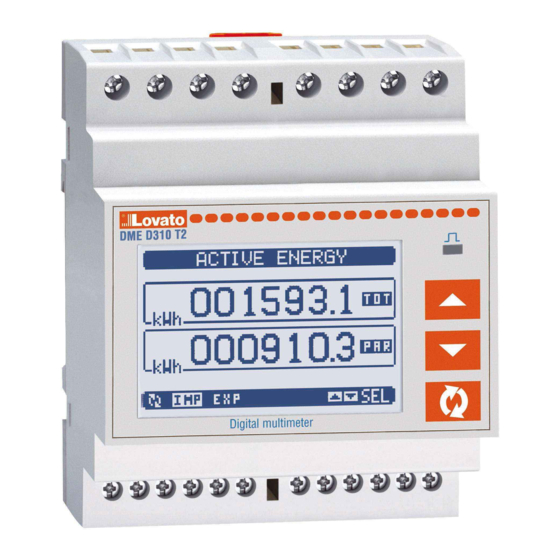
DESCRIPTION
- Modular housing, 4U (72mm wide) for 35mm DIN rail
- Graphic LCD display, 128x80 pixels, white backlight, 4 levels of grey
- Membrane keyboard with 3 keys for viewing and setting.
- Metrological LED for energy flow indication.
- Active energy measurements complies EN 50470-3 class B.
- MID compliant.
- Connection through external CTs.
- Programmable input (e.g. for tariff selection)
- 2 programmable static outputs.
- Total active and reactive energy meters.
- Partial active and reactive energy meters, resettable.
- Hour counter, total and partial.
- Easy and fast navigation.
- Texts for measurements, set-up and messages in 5 languages.
- Optical interface for max 3 expansion modules EXM series.
- Sealable terminal covers.
- Advanced programmable I/O functions.
- True RMS measurements.
GB
THREE-PHASE ENERGY METER WITH CT CURRENT INPUTS
Instructions manual
DME D310 T2 MID
G
B
Page
1
1
2
2
3
3
3
4
4
4
5
5
5
6
6
6
7
7
7
8
11
11
12
13
13
13
1
Advertisement
Chapters
Table of Contents

Related Manuals for LOVATO ELECTRIC DME D310 T2 MID


Summary of Contents for LOVATO ELECTRIC DME D310 T2 MID
-
Page 1: Table Of Contents
Mechanical dimensions INTRODUCTION The DME D310 T2 MID energy meter has been designed to combine the maximum possible ease of operation together with a wide choice of advanced functions. The active energy measurement complies with EN50470-3 (MID class B). The great accuracy, the ease of installation and operation make it an optimal choice for energy management and cost allocation tasks. -
Page 2: Keyboard Functions
KEYBOARD FUNCTIONS L and M keys - Used to scroll display pages, to select among possible choices, and to modify settings (increment-decrement). key – Used to rotate through sub-pages, to confirm a choice, to switch between viewing modes. VIEWING OF MEASUREMENTS –... -
Page 3: Table Of Display Pages
TABLE OF DISPLAY PAGES Selection with L and M Selection with N° PAGE SUB PAGES ACTIVE ENERGY – ACTIVE POWER kWh(TOT) – kW (TOT) – Bar graph ACTIVE ENERGY kWh(TOT) – kWh(PAR) REACTIVE ENERGY kvarh(TOT) – kvarh(PAR) APPARENT ENERGY kVA(TOT) – kVA(PAR) ENERGY METERS - System kWh(IMP), kWh(EXP), kvarh(IMP), kvarh(EXP), kVAh L1 PHASE ENERGY METERS... -
Page 4: Trend Graph Page
TREND GRAPH PAGE – The trend graph page allows to show the changes in the time domain of one measurement selectable among the following: • Average equivalent voltage • Average total active power • Average total reactive power • Average total apparent power. –... -
Page 5: Main Menu
EXPANDABILITY – Thanks to its built-in optical infrared interface, the DME D310 T2 MID can be expanded with EXM series modules. – These modules have an optical interface on the left side for the connection to the base unit and a second interface on the right side for the connection of an additional expansion module. -
Page 6: Additional Resources
OUTx. – The DME D310 T2 MID incorporates, in the base unit, one digital input in VAC (named INP1) and two static outputs (OUT1 and OUT2). The INP2 input is reserved for future applications, it is not available and cannot be used. -
Page 7: Remote-Controlled Variables
– Those are variables which status can be modified by the user through the communication protocol and that can be used in combination with outputs. – Example: using a remote variable (REMx) as a source for an output (OUTx), it will be possible to freely energise or de-energise one relay through the supervision software. This allows to use the DME D310 T2 MID relays to drive lighting or similar loads. -
Page 8: Table Of Parameters
P01.01 – CT primary winding rated current. P01.02 – CT secondary winding rated current. For DME D310 T2 MID fixed to 5A. P01.05 – Set this parameter according to the used wiring diagram. See wiring diagrams on last pages of the manual. - Page 9 M04 - INTEGRATION Default Range P04.01 Integration mode Shift Fixed Shift Sync P04.02 Power integration time 1-60min P04.03 Current integration time 1-60min P04.04 Voltage integration time 1-60min P04.05 Frequency integration time 1-60min P04.01 – Selection of average reading calculation method: Fixed - Readings are integrated for the set time.
- Page 10 M08 - LIMIT TRESHOLDS Default Range P08.n.01 Reference measurement OFF- (measurements) P08.n.02 Function Max – Min – Min+Max P08.n.03 Upper threshold -9999 - +9999 P08.n.04 Multiplier /100 – x10k P08.n.05 Delay 0.0 – 600.0 P08.n.06 Lower threshold -9999 - +9999 P08.n.07 Multiplier /100 –...
-
Page 11: Commands Menu
M14 - OUTPUTS Default Range P14.n.01 Output function OFF-ON-SEQ- LIMx-PULx-REMx P14.n.02 Channel number (x) 1 - 8 P14.n.03 Idle status OFF-ON Note: This menu is divided into 4 sections, for digital outputs OUT1..4 P14.n.01 – Function of the output: OFF – Output disabled ON –... -
Page 12: Technical Characteristics
TECHNICAL CHARACTERISTICS Voltage Insulation Rated voltage Us 230V Rated insulation voltage Ui 250V 400V Rated impulse withstand voltage Uimp Device can operate with or without N Power frequency withstand voltage Operating voltage range 187…264V Supply / measurement connections and tariff 323...456V Type of terminal Screw (fixed) -
Page 13: Wiring Diagrams
WIRING DIAGRAMS 3 x 400VV~ L-L 3 x 230V~ L-N Pulse output connection 30VDC - 50mA max NOTES METER PNP out NPN out 1 - Recommended fuses: Voltage measurement input: Ox+ Ox- Fast-acting 1A 2 - S2 terminals are internally jumpered. -
Page 14: Introduzione
Dimensioni meccaniche INTRODUZIONE Il contatore di energia DME D310 T2 MID è stato progettato per unire la massima semplicità di utilizzo con una ampia scelta di funzioni avanzate. La misurazione dell’energia è conforme alla norma EN50470-3 (MID classe B). L’ottima accuratezza delle misure, la semplicità di installazione e di utilizzo ne fanno una scelta ottimale per la gestione ed il monitoraggio dei consumi di energia. Il display grafico LCD consente una interfaccia utente chiara ed intuitiva. -
Page 15: Funzione Dei Tasti Frontali
FUNZIONE DEI TASTI FRONTALI Tasti L e M - Servono per lo scorrimento fra le pagine video, per la selezione fra le possibili scelte presentate a display e per la modifica di impostazioni (incremento/decremento). Tasto - Serve per lo scorrimento delle sotto-pagine, per confermare una scelta effettuata e per passare da una modalità all’altra di visualizzazione. VISUALIZZAZIONE DELLE MISURE –... -
Page 16: Tabella Delle Pagine Del Display
TABELLA DELLE PAGINE DEL DISPLAY Selezione con L e M Selezione con N° PAGINE SOTTOPAGINE ENERGIA ATTIVA – POTENZA ATTIVA kWh(TOT) – kW (TOT) – Bar graph ENERGIA ATTIVA kWh(TOT) – kWh(PAR) ENERGIA REATTIVA kvarh(TOT) – kvarh(PAR) ENERGIA APPARENTE kVA(TOT) – kVA(PAR) CONTATORI DI ENERGIA - Sistema kWh(IMP), kWh(EXP), kvarh(IMP), kvarh(EXP), kVAh CONTATORI DI ENERGIA FASE L1... -
Page 17: Pagina Grafico Trend
PAGINA GRAFICO TREND – La pagina trend consente di visualizzare un grafico con l’andamento nel tempo di una misura definita dall’utente, selezionabile fra: • tensione equivalente integrata • potenza attiva totale integrata • potenza reattiva totale integrata • potenza apparente totale integrata –... -
Page 18: Menu Principale
ESPANDIBILITÀ – Grazie alla sua interfaccia ottica a raggi infrarossi incorporata, il DME D310 T2 MID può essere espanso con dei moduli aggiuntivi della serie EXM. – Questi moduli sono a loro volta dotati di un’interfaccia ottica sul lato sinistro per il collegamento all’unità base e di una seconda sul lato destro per il collegamento di un ulteriore modulo di espansione. -
Page 19: Risorse Aggiuntive
Allo stesso modo, le uscite digitali sono denominate OUTx. – Bisogna considerare che il DME D310 T2 MID incorpora nella unità base un ingresso digitale in VAC (denominato INP1) e due uscite statiche (OUT1 e OUT2). L’ingresso INP2 è riservato per future applicazioni. -
Page 20: Variabili Da Remoto
TARIFFE – Per il conteggio dell’energia, il DME D310 T2 MID ha la possibilità di gestire 4 tariffe indipendenti oltre alla totale e alla parziale. – La selezione delle tariffe avviene normalmente tramite degli ingressi digitali, oppure in opzione tramite l’invio di messaggi sul protocollo di comunicazione. -
Page 21: Tabella Dei Parametri
P01.01 – Corrente nominale del primario dei TA. P01.02 – Corrente del secondario dei TA. Per DME D310 T2 MID fissa a 5A. P01.05 – Impostare concordemente allo schema di collegamento utilizzato. Vedere Schemi di collegamento alla fine del manuale. - Page 22 M04 - INTEGRAZIONE Default Range P04.01 Modo integrazione Scorr. Fisso Scorrevole Sincronismo P04.02 Tempo integrazione potenze 1-60min P04.03 Tempo integrazione correnti 1-60min P04.04 Tempo di integrazione tensioni 1-60min P04.05 Tempo di integrazione frequenza 1-60min P04.01 – Selezione della modalità di calcolo delle misure integrate. Fisso - Le misure istantanee vengono integrate per il tempo impostato.
- Page 23 M08 - SOGLIE LIMITE Default Range P08.n.01 Misura di riferimento OFF (misure) P08.n.02 Funzione Max - Min - Min+Max P08.n.03 Soglia superiore -9999 - +9999 P08.n.04 Moltiplicatore /100 - x10k P08.n.05 Ritardo 0,0 - 600,0 P08.n.06 Soglia inferiore -9999 - +9999 P08.n.07 Moltiplicatore /100 - x10k P08.n.08 Ritardo...
-
Page 24: Menu Comandi
M14 - USCITE Default Range P14.n.01 Funzione di uscita OFF-ON-SEQ- LIMx-PULx-REMx P14.n.02 Numero canale (x) 1 - 8 P14.n.03 Stato a riposo OFF-ON Nota: questo menu è diviso in 4 sezioni, per le uscite OUT1..4 P14.n.01 – Funzione della uscita: OFF –... -
Page 25: Caratteristiche Tecniche
CARATTERISTICHE TECNICHE Tensione Isolamento Tensione nominale Us 230V Tensione nominale d’isolamento Ui 250V 400V Tensione nominale di tenuta a impulso Uimp L’apparecchio può funzionare con o senza neutro Tensione di tenuta a frequenza d’esercizio Limiti di funzionamento 187…264V Connessioni circuito alimentazione / misura e tariffa 323...456 V Tipo di morsetti A vite (fissi) -
Page 26: Schemi Di Connessione
SCHEMI DI CONNESSIONE 3 x 400VV~ L-L 3 x 230V~ L-N Pulse output connection 30VDC - 50mA max NOTE METER PNP out NPN out 1 - Fusibili raccomandati: Ingresso misura tensione: Ox+ Ox- 1A rapido 2 - I morsetti S2 sono internamente connessi fra di loro.
Need help?
Do you have a question about the DME D310 T2 MID and is the answer not in the manual?
Questions and answers