LOVATO ELECTRIC DME D310 T2 Instruction Manual
Three-phase energy meter with ct current inputs
Hide thumbs
Also See for DME D310 T2:
- Instruction manual (26 pages) ,
- Instruction manual (24 pages) ,
- Instruction manual (24 pages)
Table of Contents
Advertisement
Quick Links
ATTENZIONE!!
● Leggere attentamente il manuale prima dell'utilizzo e
l'installazione.
● Questi apparecchi devono essere installati da personale
qualificato, nel rispetto delle vigenti normative impiantistiche, allo
scopo di evitare danni a persone o cose.
● Prima di qualsiasi intervento sullo strumento, togliere tensione dagli ingressi di
misura e di alimentazione e cortocircuitare i trasformatori di corrente.
● Il costruttore non si assume responsabilità in merito alla sicurezza elettrica in caso
di utilizzo improprio del dispositivo.
● I prodotti descritti in questo documento sono suscettibili in qualsiasi momento di
evoluzioni o di modifiche. Le descrizioni ed i dati a catalogo non possono pertanto
avere alcun valore contrattuale.
● Un interruttore o disgiuntore va compreso nell'impianto elettrico dell'edificio. Esso
deve trovarsi in stretta vicinanza dell'apparecchio ed essere facilmente raggiungibile
da parte dell'operatore. Deve essere marchiato come il dispositivo di interruzione
dell'apparecchio: IEC/ EN 61010-1 § 6.12.2.1.
● Installare lo strumento in contenitore e/o quadro elettrico con grado di protezione
minimo IP40.
● Pulire lo strumento con panno morbido, non usare prodotti abrasivi, detergenti
liquidi o solventi.
Indice
Doc: MHIT101D0408.doc
DME D310 T2
Contatore di energia trifase
con ingressi di corrente da TA
MANUALE OPERATIVO
Pagina
2
2
2
3
4
5
5
5
6
7
7
8
8
8
8
10
10
11
11
15
15
17
18
18
18
DME D310 T2
Three-phase energy meter
with CT current inputs
INSTRUCTIONS MANUAL
WARNING!
• Carefully read the manual before the installation or use.
• This equipment is to be installed by qualified personnel,
complying to current standards, to avoid damages or safety
hazards.
● Before any maintenance operation on the device, remove all the voltages from
measuring and supply inputs and short-circuit the CT input terminals.
● The manufacturer cannot be held responsible for electrical safety in case of
improper use of the equipment.
● Products illustrated herein are subject to alteration and changes without prior
notice.
● Technical data and descriptions in the documentation are accurate, to the best
of our knowledge, but no liabilities for errors, omissions or contingencies arising
there from are accepted.
● A circuit breaker must be included in the electrical installation of the building. It
must be installed close by the equipment and within easy reach of the operator.
It must be marked as the disconnecting device of the equipment:
IEC /EN 61010-1 § 6.12.2.1.
● Fit the instrument in an enclosure or cabinet with minimum IP40 degree
protection.
●
Clean the instrument with a soft dry cloth; do not use abrasives, liquid
detergents or solvents.
Index
Energy meters page
Hour counters page
Trend graph page
Counters page
29/11/2010
Page
2
2
2
3
4
5
5
5
6
7
7
8
8
8
8
10
10
11
11
15
15
17
18
18
18
p. 1 / 18
Advertisement
Table of Contents

Subscribe to Our Youtube Channel
Related Manuals for LOVATO ELECTRIC DME D310 T2


Summary of Contents for LOVATO ELECTRIC DME D310 T2
-
Page 1: Table Of Contents
DME D310 T2 DME D310 T2 Contatore di energia trifase Three-phase energy meter con ingressi di corrente da TA with CT current inputs MANUALE OPERATIVO INSTRUCTIONS MANUAL ATTENZIONE!! WARNING! ● Leggere attentamente il manuale prima dell’utilizzo e • Carefully read the manual before the installation or use. -
Page 2: Introduzione
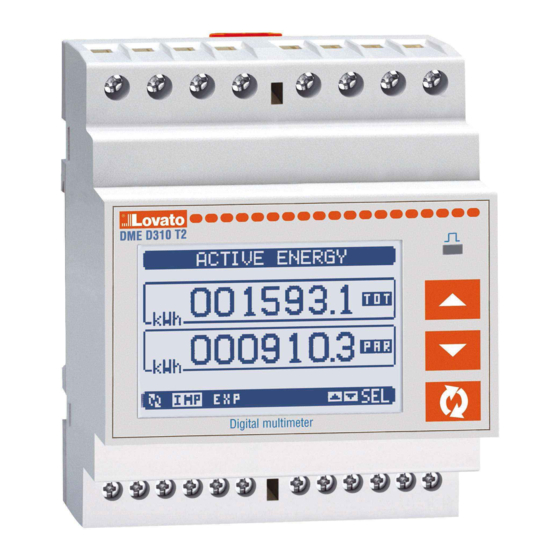
Introduzione Introduction Il contatore di energia DME310T2 è stato progettato per unire la massima The DME310T2 energy meter has been designed to combine the semplicità di utilizzo con una ampia scelta di funzioni avanzate. maximum possible ease of operation together with a wide choice of L’ottima accuratezza delle misure, la semplicità... -
Page 3: Visualizzazione Delle Misure
Visualizzazione delle misure Viewing of measurements • I tasti ▲e ▼consentono di scorrere le pagine di visualizzazione misure • The ▲and ▼keys allow to scroll the pages of viewed measurements una per volta. La pagina attuale è riconoscibile tramite la barra del titolo. one by one. -
Page 4: Tabella Delle Pagine Del Display
Tabella delle pagine del display Table of display pages Selezione con ▲e ▼ Selezione con Selection with ▲and ▼ Selection with PAGINE SOTTO-PAGINE PAGES SUB-PAGES ENERGIA ATTIVA – POTENZA ATTIVA ACTIVE ENERGY – ACTIVE POWER kWh(TOT) – kW (TOT) – Barra grafica kWh(TOT) –... -
Page 5: Pagina Contatori Di Energia
Pagina contatori di energia di sistema System energy meters page • Nella pagina contatori di energia di sistema vengono visualizzati • The System energy meters page shows the following meters contemporaneamente: simultaneously: energia attiva importata ed esportata Active energy, Imported and exported energia reattiva importata ed esportata (induttiva / capacitiva) Reactive energy, imported and exported (inductive / capacitive) energia apparente... -
Page 6: Pagina Contatori
Pagina contatori Counters page • Nella pagina contatori vengono visualizzati i conteggi CNT1…4. • The counters page displays CNT1…4 counters. • E’ possibile contare il numero di volte che un ingresso viene attivato, • It is possible to count the number of times an input is activated, or a oppure un limite viene superato ecc. -
Page 7: Menu Principale
Menu principale Main menu • Il menu principale è costituito da un insieme di icone grafiche che • The main menu is made up of a group of graphic icons (shortcuts) that permettono l’accesso rapido alle misure ed alle impostazioni. allow rapid access to measurements and settings. -
Page 8: Espandibilità
Espandibilità Expandability • Grazie alla sua interfaccia ottica a raggi infrarossi incorporata, il • Thanks to its built-in optical infrared interface, the DMED310 can be DMED310 può essere espanso con dei moduli aggiuntivi della serie expanded with EXM series modules. EXM…. -
Page 9: Ingressi, Uscite, Variabili Interne, Contatori
2 IN + 2 RELE’ 2 IN + 2 RELAYS EXM 10 01 EXM 10 01 MISTI 485 + 2 RELE’ MIXED 485 + 2 RELAYS EXM 10 20 EXM 10 20 Ingressi, uscite, variabili interne, contatori Inputs, outputs, internal variables, counters •... -
Page 10: Variabili Da Remoto
selezionata è minore della soglia inferiore o maggiore della soglia • Trip denotes either activation or de-activation of the LIM variable, superiore, dopo i rispettivi ritardi si ha l’intervento dell’uscita. Quando il depending on ‘Normal status’ setting. valore della misura rientra nei limiti si ha il ripristino immediato •... -
Page 11: Impostazione Dei Parametri (Set-Up)
Impostazione dei parametri (set-up) Parameter setting (set-up) • Dalla normale visualizzazione misure, premere contemporaneamente i • With normal viewing, press simultaneously key ▲and ▼ to recall the tasti ▲e ▼ per richiamare il menu principale,quindi selezionare l’icona General menu, then select icon and press to open the set-up e premere... - Page 12 Premendo contemporaneamente ▲e ▼la selezione alfanumerica si character selection straight to ‘A’. posiziona direttamente sul carattere ‘A’. • Press to go back to the parameter selection. The entered value is • Premere il tasto per tornare alla selezione parametri. Il valore immesso stored.
- Page 13 P04.04 Tempo di integrazione 1-60min P04.04 Voltage integration time 1-60min tensioni P04.05 Tempo di integrazione 1-60min P04.05 Frequency integration 1-60min frequenza time P04.01 – Selezione della modalità di calcolo delle misure integrate. P04.01 – Selection of average reading calculation method: Fisso = Le misure istantanee vengono integrate per il tempo impostato.
- Page 14 P07.n.01 – Indirizzo seriale (nodo) del protocollo di comunicazione. P07.n.01 – Serial address (node number) for the communication protocol. P07.n.02 – Velocità di trasmissione della porta di comunicazione. P07.n.02 – Serial communication speed. P07.n.03 – Formato dati. Impostazioni a 7 bit possibili solo per protocollo ASCII. P07.n.03 –...
-
Page 15: Menu Comandi
M13 – INGRESSI Default Range M13 – INPUTS Default Range (INPn, n=1..4) (INPn, n=1..4) P13.n.01 Funzione ingresso TAR-A OFF – ON – LOCK - P13.n.01 Input function TAR-A OFF-ON-LOCK- (n=1) SYNC-TAR-A – TAR-B (n=1) SYNC-TAR-A–TAR-B C01-C02-C03-C04- C01-C02-C03-C04- (n=2...4) C05-C06-C08 (n=2…4) C05-C06-C08 P13.n.02 Stato riposo... - Page 16 • Una volta selezionato il comando desiderato, premere • Once the required command has been selected, press per eseguirlo. Lo to execute strumento chiederà una conferma. Premendo nuovamente il comando it. The device will prompt for a confirmation. Pressing again, the verrà...
-
Page 17: Caratteristiche Tecniche
Caratteristiche tecniche Technical characteristics Tensione Voltage Tensione nominale Us 220...240V~ L-N Nominal voltage Us 220...240V~ L-N 380...415V~ L-L 380...415V~ L-L Limiti di funzionamento 187 … 264V~ L-N Operating voltage range 187 … 264V~ L-N 323...456 V~ L-L 323...456 V~ L-L Frequenza 45 …... -
Page 18: Schemi Di Connessione
APPARECCHIO LED DI CLASSE 1 CLASS 1 LED PRODUCT RADIAZIONE LED INVISIBILE INVISIBLE LED RADIATION 950 nm, max 50 µW 950 nm, max 50 µW IEC/EN 60825-1:1994 + A1:2002 + IEC/EN 60825-1:1994 + A1:2002 + A2:2001 A2:2001 Schemi di connessione Wiring diagrams 380...415V L-L 220...240V L-N...
Need help?
Do you have a question about the DME D310 T2 and is the answer not in the manual?
Questions and answers