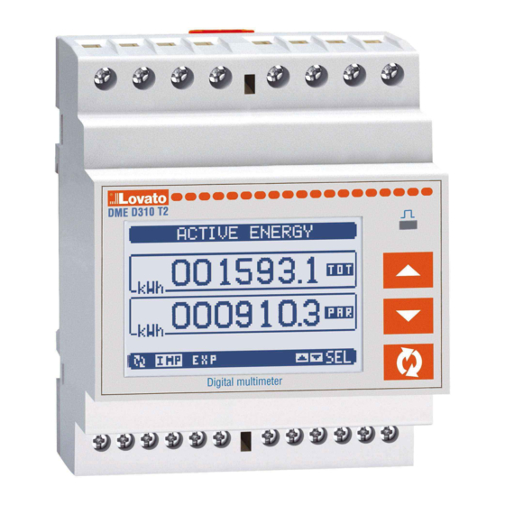
LOVATO ELECTRIC DME D310 T2 Instruction Manual
Three-phase energy meter with ct current inputs
Hide thumbs
Also See for DME D310 T2:
- Instruction manual (26 pages) ,
- Instruction manual (24 pages) ,
- Instruction manual (17 pages)
Table of Contents
Advertisement
LOVATO ELECTRIC S.P.A.
24020 GORLE (BERGAMO) ITALIA
VIA DON E. MAZZA, 12
TEL. 035 4282111
FAX (Nazionale): 035 4282200
FAX (International): +39 035 4282400
L
E
ovato
lectric.com
E-mail info@
L
E
Web
www.
ovato
lectric.com
I
GB
DME D310 T2
ATTENZIONE!!
- Leggere attentamente il manuale prima
dell'utilizzo e l'installazione.
- Questi apparecchi devono essere installati da
personale qualificato, nel rispetto delle vigenti
normative impiantistiche, allo scopo di evitare
danni a persone o cose.
- Prima di qualsiasi intervento sullo strumento,
togliere tensione dagli ingressi di misura e di
alimentazione e cortocircuitare i trasformatori
di corrente.
- Il costruttore non si assume responsabilità in
merito alla sicurezza elettrica in caso di
utilizzo improprio del dispositivo.
- I prodotti descritti in questo documento sono
suscettibili in qualsiasi momento di
evoluzioni o di modifiche. Le descrizioni ed i
dati a catalogo non possono pertanto avere
alcun valore contrattuale.
- Un interruttore o disgiuntore va compreso
nell'impianto elettrico dell'edificio.
Esso deve trovarsi in stretta vicinanza
dell'apparecchio ed essere facilmente
raggiungibile da parte dell'operatore.
Deve essere marchiato come il dispositivo di
interruzione dell'apparecchio:
IEC/EN 61010-1 § 6.11.2.
- Installare lo strumento in contenitore e/o
quadro elettrico con grado di protezione
minimo IP51.
- Pulire lo strumento con panno morbido, non
usare prodotti abrasivi, detergenti liquidi o
solventi.
INDICE
CONTATORE DI ENERGIA TRIFASE CON INGRESSI DI CORRENTE DA TA
Manuale operativo
THREE-PHASE ENERGY METER WITH CT CURRENT INPUTS
Instructions manual
WARNING!
- Carefully read the manual before the
installation or use.
- This equipment is to be installed by qualified
personnel, complying to current standards, to
avoid damages or safety hazards.
- Before any service operation on the device,
remove all the voltages from
measuring and supply inputs and short-circuit
the CT input terminals.
- The manufacturer cannot be held responsible
for electrical safety in case of improper use of
the equipment.
- Products illustrated herein are subject to
alteration and changes without prior notice.
Technical data and descriptions in the
documentation are accurate, to the best of our
knowledge, but no liabilities for errors,
omissions or contingencies arising there from
are accepted.
- A circuit breaker must be included in the
electrical installation of the building. It must
be installed close by the equipment and within
easy reach of the operator. It must be marked
as the disconnecting device of the equipment:
IEC/EN 61010-1 § 6.11.2.
- Fit the instrument in an enclosure or cabinet
with minimum IP51 protection degree.
- Clean the instrument with a soft dry cloth; do
not use abrasive products, liquid
detergents or solvents.
Pag.
INDEX
2
2
2
3
4
5
Energy meters page
5
Hour counters page
5
Trend graph page
6
Counters page
7
7
8
9
9
10
10
11
11
13
20
21
22
24
24
24
Page
2
2
2
3
4
5
5
5
6
7
7
8
9
9
10
10
11
11
13
20
21
23
24
24
24
1
Advertisement
Table of Contents

Related Manuals for LOVATO ELECTRIC DME D310 T2


Summary of Contents for LOVATO ELECTRIC DME D310 T2
-
Page 1: Table Of Contents
24020 GORLE (BERGAMO) ITALIA Instructions manual VIA DON E. MAZZA, 12 TEL. 035 4282111 FAX (Nazionale): 035 4282200 FAX (International): +39 035 4282400 ovato lectric.com DME D310 T2 E-mail info@ www. ovato lectric.com ATTENZIONE!! WARNING! – Leggere attentamente il manuale prima –... -
Page 2: Introduzione
INTRODUZIONE INTRODUCTION Il contatore di energia DME310T2 è stato The DME310T2 energy meter has been designed progettato per unire la massima semplicità di to combine the maximum possible ease of utilizzo con una ampia scelta di funzioni avanzate. operation together with a wide choice of L’ottima accuratezza delle misure, la semplicità... -
Page 3: Visualizzazione Delle Misure
VISUALIZZAZIONE DELLE MISURE VIEWING OF MEASUREMENTS – I tasti L e M consentono di scorrere le – The L and M keys allow to scroll the pages pagine di visualizzazione misure una per volta. of viewed measurements one by one. The La pagina attuale è... -
Page 4: Tabella Delle Pagine Del Display
VISUALIZZAZIONE DEL TA UTILIZZATO PROGRAMMED CT VIEWING – Su tutte le pagine che indicano i contatori di – The CT ratio currently programmed is viewed energia, viene visualizzato anche il rapporto on all the pages of the energy meters, in the del TA attualmente impostato, nella zona lower section of the status bar. -
Page 5: Pagina Contatori Di Energia
PAGINA CONTATORI DI ENERGIA DI SISTEMA SYSTEM ENERGY METERS PAGE – Nella pagina contatori di energia di sistema – The system energy meters page vengono visualizzati contemporaneamente: simultaneously shows the following meters: • energia attiva importata ed esportata • Active energy, imported and exported •... -
Page 6: Pagina Contatori
PAGINA CONTATORI COUNTERS PAGE – Nella pagina contatori vengono visualizzati i – The counters page displays CNT1…4 conteggi CNT1…4. counters. – E’ possibile contare il numero di volte che un – It is possible to count the number of times an ingresso viene attivato, oppure un limite viene input is activated, or a limit has been superato ecc. -
Page 7: Menu Principale
MENU PRINCIPALE MAIN MENU – Il menu principale è costituito da un insieme – The main menu is made up of a group of di icone grafiche che permettono l’accesso graphic icons (shortcuts) that allow rapid rapido alle misure ed alle impostazioni. access to measurements and settings. -
Page 8: Espandibilità
– Con i tasti L o M si cambia il valore della – Keys L or M change the selected digit. cifra selezionata. – Key confirms the digit and moves to the – Con il tasto si conferma la cifra e ci si next. -
Page 9: Risorse Aggiuntive
RISORSE AGGIUNTIVE ADDITIONAL RESOURCES – I moduli di espansione forniscono delle – The expansion modules provide additional risorse aggiuntive che possono essere resources that can be used through the sfruttate tramite gli opportuni menu di dedicated setup menus. impostazione. – The setup menus related to the expansions –... -
Page 10: Soglie Limite
– Lo stato di ciascun I/O e variabile interna può – The status of each I/O or internal variable can essere visualizzato sul display nella apposita be shown on the display in the dedicated pagina di stato I/O. page. SOGLIE LIMITE (LIM) LIMIT THRESHOLDS (LIM) –... -
Page 11: Tariffe
TARIFFE TARIFFS – Per il conteggio dell’energia, il DMED310 ha la – For Energy billing, the DMED310 can manage possibilità di gestire 4 tariffe indipendenti oltre 4 different tariffs in addition to the total and alla totale e alla parziale. partial energy meters. - Page 12 – Nella seguente tabella sono elencati i – The following table lists the available sottomenu disponibili sub-menus: Code Menu / Menu Descrizione / Description GENERALE Dati caratteristici dell’impianto GENERAL Detailed data of the installation UTILITA’ Lingua, luminosità, pagine display ecc. UTILITY Language, backlight, display pages, etc.
-
Page 13: Tabella Dei Parametri
– Quando si è in modalità modifica, il valore può – When the editing screen is displayed, the essere modificato con L e M. Vengono parameter setting can be modified with L M visualizzati anche una barra grafica che indica keys. - Page 14 M02 - UTILITA’ / UTILITY Default Range P02.01 Lingua English English Language Italiano Francais Espanol Portoguese P02.02 Contrasto LCD 0-100 Display contrast P02.03 Intensità retroilluminazione display alta 0-100 High backlight level P02.04 Intensità retroilluminazione display bassa 0-50 Low backlight level P02.05 Tempo passaggio a retroilluminazione bassa 5-600...
- Page 15 M04 - INTEGRAZIONE / INTEGRATION Default Range P04.01 Modo integrazione Scorr. Fisso Integration mode Scorrevole Sincronismo Fixed Shift Sync P04.02 Tempo integrazione potenze 1-60min Power integration time P04.03 Tempo integrazione correnti 1-60min Current integration time P04.04 Tempo di integrazione tensioni 1-60min Voltage integration time P04.05...
- Page 16 M06 - GRAFICO TREND / TREND GRAPH Default Range P06.01 Misura per pagina trend kW (tot) AVG VL-L (eq) AVG Measurement for trend graph kW (tot) AVG kvar (tot) AVG kVA (tot) AVG P06.02 Autorange scala OFF-ON Scale autorange P06.03 Valore fondo scala 1000 0-1000...
- Page 17 M08 - SOGLIE LIMITE / LIMIT TRESHOLDS Default Range P08.n.01 Misura di riferimento OFF (misure) Reference measure (measurements) P08.n.02 Funzione Max - Min - Min+Max Function P08.n.03 Soglia superiore -9999 - +9999 Upper threshold P08.n.04 Moltiplicatore /100 - x10k Multiplier P08.n.05 Ritardo 0.0 - 600.0 Delay...
- Page 18 M10 - CONTATORI / COUNTERS Default Range P10.n.01 Sorgente conteggio OFF-ON-INPx-LIMx Counter source P10.n.02 Numero canale (x) Channel number (x) P10.n.03 Moltiplicatore 1-1000 Multiplier P10.n.04 Divisore 1-1000 Divider P10.n.05 Descrizione del contatore CNTn (Testo – 16 caratteri) Counter description (Text – 16 chars) P10.n.06 Unità...
- Page 19 M13 - INGRESSI / INPUTS Default Range P13.n.01 Funzione ingresso TAR-A (n=1) OFF - ON - LOCK - Input function OFF (n=2...4) SYNC - TAR-A - TAR-B – C01 – C02 – C03 – C04 – C05 – C06 – C08 P13.n.02 Stato riposo OFF-ON Normal status...
-
Page 20: Menu Comandi
MENU COMANDI COMMANDS MENU – Il menu comandi permette di eseguire – The commands menu allows executing some operazioni saltuarie quali azzeramenti di occasional operations like reading peaks or misure, contatori, allarmi, ecc. counters or alarms clearing, etc. – Se è stata immessa la password per accesso –... -
Page 21: Test Di Collegamento
TEST DI COLLEGAMENTO WIRING TEST – Il test di collegamento consente di verificare – The wiring test allows to verify if the se l’installazione del multimetro è stata connection of the DME device has been effettuata correttamente. executed properly. – Per poter eseguire il test, il multimetro deve –... -
Page 22: Caratteristiche Tecniche
CARATTERISTICHE TECNICHE Tensione Isolamento Tensione nominale Us 220 - 240V Tensione nominale d’isolamento Ui 250V 380 - 415V Tensione nominale di tenuta a impulso Uimp L’apparecchio può funzionare con o senza neutro Tensione di tenuta a frequenza d’esercizio Limiti di funzionamento 187 - 264V Connessioni circuito alimentazione / misura e tariffa 323 - 456V... -
Page 23: Technical Characteristics
TECHNICAL CHARACTERISTICS Voltage Insulation Rated voltage Us 220 - 240V Rated insulation voltage Ui 250V 380 - 415V Rated impulse withstand voltage Uimp Device can operate with or without N Power frequency withstand voltage Operating voltage range 187 - 264V Supply / measurement connections and tariff 323 - 456V Type of terminal... -
Page 24: Schemi Di Connessione
SCHEMI DI CONNESSIONE WIRING DIAGRAMS 380 - 415V~ L-L 220 - 240V~ L-N Pulse output connection 30V= - 50mA max METER NPN out PNP out Ox+ Ox- Tariff input Pulse output 100 - 240V~ 30V= 50mA DISPOSIZIONE MORSETTI TERMINAL ARRANGEMENT O2+ O2- DIMENSIONI MECCANICHE [mm] MECHANICAL DIMENSIONS [mm]...
Need help?
Do you have a question about the DME D310 T2 and is the answer not in the manual?
Questions and answers