Table of Contents
Advertisement
Quick Links
Advertisement
Table of Contents

Related Manuals for Supermicro AS-2125HS-TNR


Summary of Contents for Supermicro AS-2125HS-TNR
- Page 1 WEEE DISASSEMBLY INSTRUCTIONS SUPERMICRO AS -2125HS-TNR ENCLOSURE Abstract This document provides clear guidance for end-of-life recyclers on how to identify and disassemble reportable materials in compliance with the Waste Electrical and Electronic Equipment (WEEE) directive.
-
Page 2: Table Of Contents
Table of Contents Product Views ............................3 Reportable Materials on AS -2125HS-TNR ....................5 Disassemble Instructions .......................... 5 3.3 Step-by-Step Disassembly Instructions ....................8 Removing Cable and Chassis Top Cover ..................8 Removing Hard Disk Drive (HDD) / Solid State Drive (SDD) ............9 Removing Power Supply ...................... -
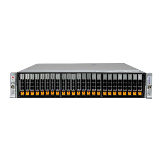
Page 3: Product Views
Product Views Front view Rear view Product construct view Hard Disk Drive/ Solid State Drive Backplane Fans... - Page 4 Power Supply Add-On Module AIOM Card AIOM Cable Motherboard Processor DIMM...
-
Page 5: Reportable Materials On As -2125Hs-Tnr
1. Reportable Materials on AS -2125HS-TNR According to Article 8(2) and Annex VII of WEEE directive 2012/19/EU, Below materials and components should be selectively treated. Description Notes Quantity With a surface greater than 10 sq cm 2.4, 3.5, 4.1, 5.1, 6.1, 8.1, Printed Circuit Boards (PCB) or (Depending on the product 9.2, 10.2, 11.1,12.1, 13.1,... - Page 6 The intent of this document is to provide guidance to recyclers on the presence of materials and components at the product / family level, as required by the EU WEEE Directive 2012/10/EU. This document should also help direct recyclers to proper methods for removing parts and general product disassembly instructions.
- Page 7 Chassis Backplane Fans Screws Motherboard, Riser Cards, Backplane, Add- On Module, AIOM Cable Battery Cables Power Supply Air Shroud Power Supply Power Enclosure*2 Screws and Standoff*2 Set Power Supply Module*2 Storage Card and CPU...
-
Page 8: Step-By-Step Disassembly Instructions
Heat Sink Processor SSD *2set Natwork Card *3 Add-On Module DIMM *4Set Power Cable M.2 *2 3.3 Step-by-Step Disassembly Instructions 1. Removing Cable and Chassis Top Cover 1. Use the operating system to power down the system. 2. After the system has completely shut-down, disconnect the power cords from the power supply modules. -
Page 9: Removing Hard Disk Drive (Hdd) / Solid State Drive (Sdd)
Description Description Power Cable Chassis BMC LAN Port Top Cover USB 3.0 Ports VGA Port PCIe 5.0 x16 AIOM Slot (NCSI) 2. Removing Hard Disk Drive (HDD) / Solid State Drive (SDD) 1. Press the release button to extend the drive carrier handle. 2. - Page 10 and lift the SSD out from the posts as shown below: 5. Use a cross screwdriver to remove the drive enclosure 6. Use a cross screwdriver to remove screws and lift off the PCB Description HDD/ SSD Hard Drive Enclosure Hard Drive PCB...
-
Page 11: Removing Power Supply
3. Removing Power Supply 1. Press the release tab on the power supply. 2. Use the handle to gently slide the power supply out the back of the chassis. 3. Remove the screw from the enclosure 4. Cut the power leads connected to the fan and lift the main board from the chassis... -
Page 12: Removing Advanced I/O (Aiom) Network Card
Use a flathead screwdriver to cut the capacitor adhesive and pin solder. Adhesive Description Power Supply Power Enclosure Fan Cable Power Module PCB Capacitor 4. Removing Advanced I/O (AIOM) Network Card 1. Loosen the thumbscrew using your hand. 2. Slide the AIOM out of the opening. Description AIOM Network Card... -
Page 13: Removing Aiom Cable
5. Removing AIOM Cable 1. Unscrew the two screws (circled in red) using a screwdriver and loosen the thumb screw by hand. 2. Remove the cable from the motherboard. Thumb Screw Description AIOM Cable 6. Removing Add-on Module (AOM) 1. Loosen the thumbscrew and press down on the push pin. 2. -
Page 14: Removing Fan
7. Removing Fan 1. Disconnect the chassis fan from the motherboard fan connectors as shown below. 2. Squeeze the fan tab as circled in red and lift the fan housing up and out of the chassis for each fan. Description Cooling Fans 8. -
Page 15: Removing Riser Bracket And Riser Card
9. Removing the Riser Bracket and Riser Card 1. Disconnect any cables connecting the riser cards to the system. 2. Press the blue tab on the riser card and lift the riser card bracket away from the chassis 3. Unscrew the thumb screw holding the riser card and remove the riser card from the bracket. Thumb Screw Description Riser Card Bracket... - Page 16 3. Once the screws have been removed, lift the heatsink module off the socket. 4. Loosen the socket screw. 5. Gently remove the processor from the socket. Note: Please handle the processor with care to avoid damaging it or its pins Description 10.1 Heat Sink...
-
Page 17: Removing Dimm
11. Removing DIMM 11.1 1. Hand press both release tabs on the ends of the DIMM module to unlock it 2. Once the DIMM module is loose, remove it from the memory slot Description 11.1 DIMM 12. Removing the Network Card 1. -
Page 18: Removing The Power Supply Shroud
13.1 Description 13.1 14. Removing the Power Supply Shroud 1. Locate the Power Supply Shroud on the motherboard and lift it out of the system by using the latch. 14.1 Description 14.1 Power Supply Shroud 15. Removing Motherboard 1. Unscrew the screws (circled in red) on the motherboard and lift the motherboard out of the chassis. 2. -
Page 19: Removing Control Panel
15.1 15.2 Description 15.1 Motherboard 15.2 Battery 16. Removing Control Panel Remove control panel screw (R and L) from the chassis. - Page 20 16.1 16.2 Remove backet screw and hand screw (R and L) from control panel and used hand remove backet mylar. Description 16.1 Control Panel Cover L & R 16.2 MYLAR_L & R When all the steps are complete, the chassis enclosure can be recycled.
Need help?
Do you have a question about the AS-2125HS-TNR and is the answer not in the manual?
Questions and answers