Sign In
Upload
Download
Table of Contents
Contents
Add to my manuals
Delete from my manuals
Share
URL of this page:
HTML Link:
Bookmark this page
Add
Manual will be automatically added to "My Manuals"
Print this page
×
Bookmark added
×
Added to my manuals
Manuals
Brands
Supermicro Manuals
Server
A+ AS-2124BT-HTR
User manual
Supermicro A+ AS-2124BT-HTR User Manual
Hide thumbs
1
2
3
Table Of Contents
4
5
6
7
8
9
10
11
12
13
14
15
16
17
18
19
20
21
22
23
24
25
26
27
28
29
30
31
32
33
34
35
36
37
38
39
40
41
42
43
44
45
46
47
48
49
50
51
52
53
54
55
56
57
58
59
60
61
62
63
64
65
66
67
68
69
70
71
72
73
74
75
76
77
78
79
80
81
82
83
84
85
86
87
88
89
90
91
92
93
94
95
96
97
98
99
100
101
102
103
104
105
106
107
108
109
110
111
112
113
114
115
116
117
118
119
120
page
of
120
Go
/
120
Contents
Table of Contents
Bookmarks
Table of Contents
Table of Contents
Chapter 1 Introduction
Overview
Unpacking the System
System Features
Server Chassis Features
Control Panel
Front Features
Rear Features
Input/Output Ports
SIOM Network Ports
Node Trays
Motherboard Layout
Quick Reference
System Block Diagram
Where to Get Replacement Components
Returning Merchandise for Service
Chapter 2 Server Installation
Overview
Preparing for Setup
Choosing a Setup Location
Rack Precautions
Server Precautions
Rack Mounting Considerations
Ambient Operating Temperature
Airflow
Mechanical Loading
Circuit Overloading
Reliable Ground
Rack Mounting Instructions
Overview of the Rack Rails
Adjusting the Rail Length
Installing the Rails on a Rack
Chassis Installation
Chapter 3 Maintenance and Component Installation
Removing Power
Removing Power from a Node
Removing Power from the System
Accessing the System
Removing a Computing Node Drawer
Removing the Chassis Cover
Motherboard Components
Processor and Heatsink Installation
Heatsinks
Memory Support and Installation
Memory Support
DIMM Module Population
Installing Memory
Motherboard Battery
Chassis Components
Storage Drives
Drive Carriers
Drive Configuration
Installing Drives
Installing an M.2 Solid State Drive
Installing Expansion Cards
SIOM Card
System Fans
Checking the Server Air Flow
Overheating
Power Supply
Chapter 4 Motherboard Connections
Headers and Connectors
Front Control Panel Connector
Ports
Jumpers
LED Indicators
Pciexpress Slots
Chapter 5 Software
Microsoft Windows os Installation
Driver Installation
Superdoctor ® 5
Ipmi
Chapter 6 BIOS
Introduction
Starting BIOS Setup Utility
Main Setup
Advanced Setup Configurations
Ipmi
Event Logs
Security
Boot
Save & Exit
BIOS Update Using IPMI
Appendix A IPMI Crash Dump
Appendix B Standardized Warning Statements for AC Systems
Appendix C System Specifications
Appendix D UEFI BIOS Recovery
Advertisement
Quick Links
Download this manual
A+ Server
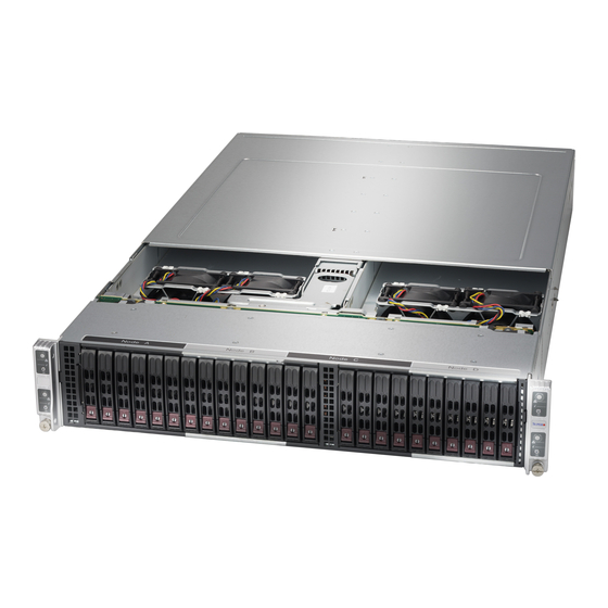
AS -2124BT-HTR
AS -2124BT-HNTR
USER'S MANUAL
Revision 1.1a
Table of
Contents
Previous
Page
Next
Page
1
2
3
4
5
Advertisement
Table of Contents
Need help?
Do you have a question about the A+ AS-2124BT-HTR and is the answer not in the manual?
Ask a question
Questions and answers
Related Manuals for Supermicro A+ AS-2124BT-HTR
Server Supermicro AS-2113S-WN24RT User Manual
A+ server (120 pages)
Server Supermicro AS-2124US-TNR User Manual
A+ server (131 pages)
Server Supermicro A+ AS-2124US-TNRP User Manual
(130 pages)
Server Supermicro AS-2113S-WTRT User Manual
A+ server (119 pages)
Server Supermicro A+ AS-2124BT-HNTR User Manual
(120 pages)
Server Supermicro AS-2114GT-DPNR User Manual
A+ server (130 pages)
Server Supermicro AS-2114S-WN24RT User Manual
A+ server (123 pages)
Server Supermicro AS-2123BT-HNR Information
(13 pages)
Server Supermicro AS-2125HS-TNR User Manual
(109 pages)
Server Supermicro AS-2125HS-TNR Disassembly Instructions Manual
Enclosure (20 pages)
Server Supermicro A+ Server AS-2115HS-TNR User Manual
(119 pages)
Server Supermicro A+ Workstation AS-2115HV-TNRT User Manual
(125 pages)
Server Supermicro A+ Server AS-2126HS-TN User Manual
(200 pages)
Server Supermicro AS-2124GQ-NART User Manual
A+ server (121 pages)
Server Supermicro A+ Server AS-2015CS-TNR User Manual
(120 pages)
Server Supermicro AS-2025HS-TNR Disassembly Instructions Manual
Enclosure (16 pages)
This manual is also suitable for:
A+ as-2124bt-hntr
Table of Contents
Print
Rename the bookmark
Delete bookmark?
Delete from my manuals?
Login
Sign In
OR
Sign in with Facebook
Sign in with Google
Upload manual
Upload from disk
Upload from URL


Need help?
Do you have a question about the A+ AS-2124BT-HTR and is the answer not in the manual?
Questions and answers