Table of Contents
Advertisement
Quick Links
Advertisement
Table of Contents

Related Manuals for Perma STAR CONTROL 120


Summary of Contents for Perma STAR CONTROL 120
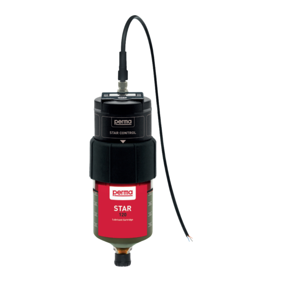
- Page 1 STAR CONTROL Installation Guide The Expert in Lubrication Solutions...
- Page 2 © 2023 perma-tec GmbH & Co. KG The content of this document has been compiled by perma-tec with meticulous care. Nevertheless, we cannot rule out deviations and reserve the right to make technical changes to the product without any advance notice. We do not assume any judicial responsibility or liability for any damages which may ensue as a result.
- Page 3 Replace the application‘s grease fitting with a suitable reducer. perma offers a wide assortment of reducers, extensions, tubes, • brackets and other accessories. Ensure that the lube point is prefilled with fresh lubricant before installation. perma offers all of its lubricants in 400 g • cartridges for grease guns.
-
Page 4: Mounting Types
(109420) for all angled or horizontal installations Reducer for thread connection Installation of perma STAR CONTROL is possible in all directions (indoors and outdoors). Protection cap can only be used for vertical installations (outlet at the bottom) or horizontal installations! - Page 5 Keep connection lines as short as possible and use tubes with an inside diameter of at least 6 mm. Keep in mind that tube length and bore diameter of bearing housings affect pressure. For installation of perma STAR CONTROL use Mounting bracket STAR. Secure tubes with suitable fastenings (brackets, cable ties) to protect against damage and tearing.Depending on lubricant and ambient temperature, different...
-
Page 6: Direct Mounting
Loctite® 243™ Direct mounting All oil-filled perma STAR LCs come with an integrated oil retaining valve. They can be installed directly to an lubrication brush without the need for an additional oil retaining valve. ACCESSORY KIT STAR Chains (117982) - Page 7 Protection cap STAR VARIO Standard Duty 250 (109519) • Protection cap STAR Heavy Duty 250 (109999) • Protection cap STAR Heavy Duty 250 perma STAR CONTROL Drive Adapter cable © 2023 | perma-tec GmbH & Co. KG | www.perma-tec.com |...
- Page 8 1. Prior to installation, lubrication point must be cleaned to protect against contamination. 2. Remove grease nipple or plug screw of connecting thread and check thread size. Determine thread size at the lubrication point with perma fitting thread tester (110374). 3. Insert reducer and install tube / hose and necessary accessory parts.
- Page 9 5. Prefill lubrication point and all grease lines for remote installation. 6. Use a tube prefill adapter to prefill lubrication point and grease lines: KIT TUBE PREFILL ADAPTERS (117907) © 2023 | perma-tec GmbH & Co. KG | www.perma-tec.com |...
-
Page 10: Pressure Testing
Check counter pressure at lubrication point before installing the lubrication system to guarantee correct function. Most bearings require 0.5 - 2 bar pressure (without extension tubes / hoses). perma STAR CONTROL can be used for these lubrication points. perma STAR CONTROL... - Page 11 (Caution: Observe accident prevention regulations). Open stop valve. Push SET button on perma STAR CONTROL for approx. 10 seconds until PU lights up on display to trigger an additional discharge / purge. Watch the pressure on the gauge during the additional discharge. If pressure exceeds 7.5 bar the lubrication system will shut off automatically.
-
Page 12: Activation And Installation
Power supply through connection of brown wire (pin 1; power supply +V DC) and blue wire (pin 3, power supply GND) • The operating mode of perma STAR CONTROL is displayed via the white wire (pin 2 - OK signalled / discharging) or the black wire (pin •... - Page 13 There is no need to use extra blocking diodes at the outputs if the drives are connected in parallel. The example shows a wiring diagram of a parallel circuit of 4 perma STAR CONTROL: © 2023 | perma-tec GmbH & Co. KG | www.perma-tec.com |...
-
Page 14: Setting The Mode
Configuration TIME MODE TIME 1 x = MODE Hold down SET button Release SET button > IMPULSE > 1 x = LC 60 2 x = LC 120 3 x = LC 250 4 x = LC 500 Check complete configuration when changing the setting. - Page 15 1 x = LC 60 3 x = LC 250 2 x = LC 120 4 x = LC 500 • The change is applied after 3 s (without pressing the SET button) © 2023 | perma-tec GmbH & Co. KG | www.perma-tec.com |...
- Page 16 Manufactured by: perma-tec GmbH & Co. KG perma Multipurpose grease SF01 Hammelburger Str. 21 | 97717 EUERDORF www.perma-tec.com | Tel.: +49 9704 609-0 Made in Germany 120 cm³ / 4.06 fl.oz. (US) Installation date and exchange date Art. No. | Serial number...
- Page 17 NOTES © 2023 | perma-tec GmbH & Co. KG | www.perma-tec.com |...
- Page 18 NOTES...
- Page 19 © 2023 | perma-tec GmbH & Co. KG | www.perma-tec.com |...
- Page 20 GmbH & Co. KG Hammelburger Str. 21 97717 Euerdorf GERMANY Tel.: +49 9704 609 - 0 info@perma-tec.com www.perma-tec.com...
Need help?
Do you have a question about the STAR CONTROL 120 and is the answer not in the manual?
Questions and answers