
Subscribe to Our Youtube Channel
Related Manuals for ASRock Industrial IMB-A8000


Summary of Contents for ASRock Industrial IMB-A8000
- Page 1 IMB-A8000 User Manual Version 1.0 Published October 29, 2024 Copyright©2024 ASRockInd INC. All rights reserved.
-
Page 2: Copyright Notice
Version 1.0 Published October, 2024 Copyright©2024 ASRockInd INC. All rights reserved. Copyright Notice: No part of this documentation may be reproduced, transcribed, transmitted, or translated in any language, in any form or by any means, except duplication of documentation by the purchaser for backup purpose, without written consent of ASRockInd Inc. - Page 3 WARNING THIS PRODUCT CONTAINS A BUTTON BATTERY If swallowed, a button battery can cause serious injury or death. Please keep batteries out of sight or reach of children. CALIFORNIA, USA ONLY The Lithium battery adopted on this motherboard contains Perchlorate, a toxic substance controlled in Perchlorate Best Management Practices (BMP) regulations passed by the California Legislature.
- Page 4 *15G062470003AI* P/N: 15G062470003AI V1.2 Button Battery Safety Notice Button Battery Safety Notice WARNING • INGESTION HAZARD: This product contains a button cell or coin battery. • DEATH or serious injury can occur if ingested. • A swallowed button cell or coin battery can cause Internal Chemical Burns in as little as 2 hours.
-
Page 5: Table Of Contents
Contents Chapter 1 Introduction Package Contents Specifications Motherboard Layout I/O Panel Block Diagram Chapter 2 Installation Screw Holes Pre-installation Precautions Installation of Memory Modules Expansion Slots How to Use High Performance and High Power Consumption GPU Card 2.5.1 VGA-PWR Card 2.5.2 VGA-PWR600W Card Jumpers Setup... - Page 6 Main Screen Advanced Screen 3.3.1 CPU Configuration 3.3.2 Chipset Configuration 3.3.3 Storage Configuration 3.3.4 Super IO Configuration 3.3.5 ACPI Configuration 3.3.6 USB Configuration 3.3.7 Trusted Computing Hardware Health Event Monitoring Screen Security Screen Boot Screen Exit Screen...
-
Page 7: Chapter 1 Introduction
If you require technical support related to this motherboard, please visit our website for specific information about the model you are using. https://www.asrockind.com/technical-support 1.1 Package Contents ASRockInd IMB-A8000 Motherboard (Mini-ITX (6.7-in x 6.7-in x 1.6-in, 17.0 cm x 17.0 cm x 4.1 cm) Gift Package: 1 x COM Cable... -
Page 8: Specifications
1.2 Specifications Mini-ITX (6.7-in x 6.7-in x 1.6-in, 17.0 cm x 17.0 cm x 4.1 Form Factor Dimensions AMD Ryzen™ Embedded 8000 SoC processors -IMB-A8000P (PRO 8845HS, 8/16, 3.8GHz, 35-54W) Processor -IMB-A8000S (PRO 8645HS, 6/12, 4.3GHz, 35-54W) System -IMB-A8000M (PRO 8840U, 8/16, 3.3GHz, 15-30W) -IMB-A8000V (PRO 8640U, 6/12, 3.5GHz, 15-30W) BIOS AMI SPI 256 Mbit... - Page 9 IMB-A8000 Watchdog Output From Super I/O to drag RESETCON# Timer Interval 256 Segments, 0, 1, 2, ...255sec 12~28V DC-In with 4-pin wafer PWR cable or DC Input PWR Jack (Screw type) AT/ATX Supported Power - AT : Directly PWR on as power input ready...
-
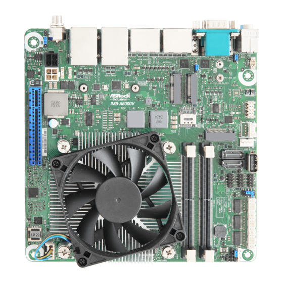
Page 10: Motherboard Layout
1.3 Motherboard Layout Top: BAT1 SMBUS_TEST1 USB2_2 PANEL1 PLED PWRBTN HDLED RESET COM3 USB2_3 Bottom: Top: HD_AUDIO1 Line Line Out SPDIF1 SATA0_PWR1 USB2_6_7 JPWR_COM1 HEATER1 CC_TALK_OUT1 M2_B1 BUZZ1 SATA3_2 SATA3_1 COM2 COM1 DDR5 B1 JPWR_COM2 M2M_1 DDR5 A1 SIM1 M2E_1 Top: USB 3.2 Gen2 USB3_5... - Page 11 IMB-A8000 Back: ESPI1...
- Page 12 1 : COM Port PWR Setting Jumpers JPWR_COM1 (For COM Port1) JPWR_COM2 (For COM Port2) 2 : Battery Connector (BAT1) 3 : M.2 Key-M Socket (M2M_1) 4 : M.2 Key-E Socket (M2E_1) 5 : M.2 Key-B Socket (M2_B1) 6 : Front Panel Audio Header (HD_AUDIO1) 7 : SMBUS_TEST1 8 : SATA Power Output Connector (SATA0_PWR1) 9 : SATA3 Connectors (SATA3_2, SATA3_1)
-
Page 13: I/O Panel
IMB-A8000 1.4 I/O Panel Audio Jack-Green: Line Out USB 3.2 Gen1 Port (USB3H_2) COM Port (COM1) (RS232/422/485)* USB 3.2 Gen2 Port (USB3_5) DisplayPort (DP2) USB 3.2 Gen1 Port (USB3_H1) DisplayPort (DP4) DisplayPort (DP3) RJ45 LAN Port (LAN1)** DisplayPort (DP1) RJ45 LAN Port (LAN2)***... - Page 14 ** There are two LEDs next to the LAN1 port. Please refer to the table below for the LAN1 port LED indications. LAN1 Port LED Indications ACT/LINK SPEED ACT/LINK LED SPEED LED Status Description Status Description No Link 10/100Mbps connection Blinking Data Activity Orange...
-
Page 15: Block Diagram
IMB-A8000 1.5 Block Diagram IMB-A8000 Series Display port Connector SO-DIMM Display port Channel A (A1) DDR5 5600MHz Connector SO-DIMM Channel B Display port DDR5 5600MHz (B1) Connector PCIe Gen4 [0:7] PCIe x8 Slot Display port Connector PCIEx1 SATAx2 ASM1061 SATA Port x2... -
Page 16: Chapter 2 Installation
ASRock Industrial has positioned the chipset on the rear of the PCB to optimize space and improve thermal dissipation when the chipset heatsink contacts the chassis via a thermal pad. -
Page 17: Installation Of Memory Modules
IMB-A8000 2.3 Installation of Memory Modules IMB-A8000 provides two 262-pin DDR5 (Double Data Rate 5) SO-DIMM slots, and supports Dual Channel Memory Technology. Please make sure to disconnect the power supply before adding or removing SO- DIMMs or the system components. - Page 18 Open the DIMM slot latches. Aligh the notch. Carefully press down until the IMM slides into the slot. The latches snap back into place.
-
Page 19: Expansion Slots
IMB-A8000 2.4 Expansion Slots There are one PCI Express slot, three M.2 sockets, and one SIM socket on this motherboard. PCIE slot: PCIE1 (PCIE 4.0 x8 slot) is used for PCI Express x8 lane width cards. M.2 sockets: 1 x M.2 (Key E, 2230) with PCIe Gen3 x1, USB 2.0 for Wireless 1 x M.2 (Key M, 2242/2280) with PCIe Gen4 x4 for SSD... -
Page 20: How To Use High Performance And High Power Consumption Gpu Card
2.5 How to Use High Performance and High Power Consumption GPU Card 2.5.1 VGA-PWR Card We suggest using ASRockInd VGA-PWR card to supply +12V input power for the PCIE add- on card under 300W. Please refer to the following diagram for instructions on connecting the VGA-PWR card and the PCIE add-on card to the motherboard. - Page 21 B. Supply power through DC-Jack with VGA-PWR card: Connect Power Adapter to DC Jack (DC_JACK1). Connect 4-pin ATX PWR Connector (Black) (ATX12V1) to 4-pin DC-IN Power Connector (DC_4PIN1). Connect EXTRA_PCIE_PWR_IN Connector (White) (DC_4PIN2) to 4-pin VGA Power Connector (VGA_PWR2). Connect PCIE_PWR1 to PS_ON# Header (PCIE_ISOLATION1). Connect VGA Power Connector (VGA_PWR1) to PCIE add-on card auxiliary power connector.
-
Page 22: Vga-Pwr600W Card
2.5.2 VGA-PWR600W Card We suggest using ASRockInd VGA-PWR600W card to supply +12V input power for the PCIE add-on card under 600W. Please refer to the following diagram for instructions on connecting the VGA-PWR600W card and the PCIE add-on card to the motherboard. •... -
Page 23: Jumpers Setup
IMB-A8000 2.6 Jumpers Setup The illustration shows how jumpers are setup. When the jumper cap is placed on pins, the jumper is “Short.” If no jumper cap is placed on pins, the jumper is “Open. ” The illustration shows a 3-pin jumper whose pin1 and pin2 are “Short”... - Page 24 PCIE_PWR_MODE Signal Name LOW_PWR_MODE (6-pin PCIE_MODE1) (Default) (see p. 4, No. 23) HIGH_PWR_MODEl Only set to HIGH_PWR_Mode (pin 2-3) when using VGA-PWR CARD.
-
Page 25: Onboard Headers And Connectors
IMB-A8000 2.7 Onboard Headers and Connectors Onboard headers and connectors are NOT jumpers. Do NOT place jumper caps over these headers and connectors. Placing jumper caps over the headers and connectors will cause per- manent damage to the motherboard! Battery Connector... - Page 26 SATA3 Connectors Signal Name (7-pin SATA3_2, SATA3_1) SATA-A+ (see p. 4, No. 9) SATA-A- SATA3_2 SATA3_1 SATA-B- SATA-B+ The Serial ATA3 (SATA3) connector supports SATA data cables for internal storage de- vices. The current SATA3 interface allows up to 6.0 Gb/s data transfer rate.
- Page 27 IMB-A8000 The front panel design may differ by chassis. A front panel module mainly consists of power switch, reset switch, power LED, hard drive activity LED, speaker and etc. When connecting your chassis front panel module to this header, make sure the wire assignments and the pin assignments are matched correctly.
- Page 28 SPDIF Header Signal Name (3-pin SPDIF1) (see p. 4 , No. 15) SPDIF OUT SPDIF header, providing SPDIF audio output to HDMI VGA card, allows the system to connect HDMI Digital TV/projector/LCD devices. Please connect the SPDIF connector of HDMI VGA card to this header.
- Page 29 IMB-A8000 EXTRA_PCIE_PWR_IN Connector (White) Signal Name Signal Name (4-pin DC_4PIN2) +12V +12V (see p. 4, No. 21) * Must use +12V from VGA-PWR CARD only. ** Do not connect to power supply. 4-pin ATX PWR Connector (Black) Signal Name Signal Name...
-
Page 30: Chapter 3 Uefi Setup Utility
Chapter 3 UEFI SETUP UTILITY 3.1 Introduction ASRock Industrial UEFI (Unified Extensible Firmware Interface) is a BIOS utility which offers tweak-friendly options in an advanced viewing interface. This BIOS utility can perform the Power-On Self-Test (POST) during system startup, re- cord hardware parameters of the system, load operating system, and so on. -
Page 31: Uefi Menu Bar
IMB-A8000 3.1.2 UEFI Menu Bar The top of the screen has a menu bar with the following selections: Main For setting system time/date information For advanced system configurations Advanced H/W Monitor Displays current hardware status Security For security settings Boot... -
Page 32: Navigation Keys
3.1.3 Navigation Keys Use < > key or < > key to choose among the selections on the menu bar, and use < > key or < > key to move the cursor up or down to select items, then press <Enter> to get into the sub screen. -
Page 33: Main Screen
IMB-A8000 3.2 Main Screen When you enter the UEFI SETUP UTILITY, the Main screen will appear and display the system overview. Because the UEFI software is constantly being updated, the following UEFI setup screens and descriptions are for reference purpose only, and they may not exactly match what you see on your screen. -
Page 34: Advanced Screen
3.3 Advanced Screen I n t h i s s ec t ion, you may s et t he con f ig u r at ions for t he fol low i ng items: CPU Configuration, Chipset Configuration, Storage Configuration, Super IO Configuration, ACPI Configuration, USB Configuration, and Trusted Computing. -
Page 35: Cpu Configuration
IMB-A8000 3.3.1 CPU Configuration PSS Support Enable/disable the generation of ACPI _PPC, _PSS, and _PCT objects. Core Performance Boost Core Performance Boost controls whether the processor transitions to a higher frequency than the processor's rated speed if the processor has available power and is within temperature specifications. -
Page 36: Chipset Configuration
3.3.2 Chipset Configuration Above 4G Decoding The option allows you to enable or disable above 4G Memory Mapped IO decoding. Configuration options: [Enabled] [Disabled] IOMMU Enable/Disable IOMMU Support. Primary Graphics Adapter The option allows you to select a primary VGA. Configuration options: [Onboard] [PCI Express] (Options vary when you have installed a graphics card on your motherboard.) Share Memory... -
Page 37: Sr-Iov Support
IMB-A8000 Re-Size BAR Support If system has Resizable BAR capable PCIe Devices, this option enables or disables Resizable BAR Support. SR-IOV Support If system has SR-IOV capable PCIe Devices, this option Enables or Disables Single Root IO Virtualization Support. Configuration options: [Enabled] [Disabled] NVMe RAID mode Enable or disable NVMe RAID mode. -
Page 38: Storage Configuration
3.3.3 Storage Configuration Third Party SATA3 Controller The option allows you to enable or disable the SATA controllers. Configuration options: [Enabled] [Disabled] Third Party SATA3 Mode AHCI supports new features that improve performance. Configuration option: [AHCI] AHCI (Advanced Host Controller Interface) supports NCQ and other new features that will improve SATA disk performancebut IDE mode does not have these advantages. -
Page 39: Super Io Configuration
IMB-A8000 3.3.4 Super IO Configuration COM1 Configuration Use this to set parameters of COM1. Type Select Use this to select COM1 port type: [RS232], [RS422] or [RS485]. COM2 Configuration Use this to set parameters of COM2. Type Select Use this to select COM2 port type: [RS232], [RS422] or [RS485]. -
Page 40: Acpi Configuration
3.3.5 ACPI Configuration PCIE Devices Power On Allows the system to be waked up by a PCIE device and enable wake on LAN. Configuration options: [Enabled] [Disabled] RTC Alarm Power On RTC Alarm Power On allows the system to be waked up by the real time clock alarm. Set it to By OS to let it be handled by your operating system. -
Page 41: Usb Configuration
IMB-A8000 3.3.6 USB Configuration USB Power Control Use this option to control USB power. -
Page 42: Trusted Computing
3.3.7 Trusted Computing NOTE: Options vary depending on the version of your connected TPM module. Security Device Support Security Device Support allows you to enable or disable BIOS support for security device. O.S. will not show Security Device. TCG EFI protocol and INT1A interface will not be available. -
Page 43: Pending Operation
IMB-A8000 Pending Operation Pending Operation allows you to schedule an Operation for the Security Device. NOTE: Your computer will reboot during restart in order to change State of the Device. Configuration options: [None] [TPM Clear] Platform Hierarchy This item allows you to enable or disable Platform Hierarchy. -
Page 44: Hardware Health Event Monitoring Screen
3.4 Hardware Health Event Monitoring Screen This section allows you to monitor the status of the hardware on your system, including the parameters of the CPU temperature, motherboard temperature, CPU fan speed, and the critical voltage. NOTE: Options vary depending on the features of your motherboard. CPU_Fan 1 Setting This item allows you to select a fan mode for CPU Fan 1. -
Page 45: Security Screen
IMB-A8000 3.5 Security Screen In this section you may set or change the supervisor/user password for the system. You may also clear the user password. Supervisor Password Set or change the password for the administrator account. Only the administrator has the authority to change the settings in the UEFI Setup Utility. -
Page 46: Boot Screen
3.6 Boot Screen This section displays the available devices on your system for you to configure the boot settings and the boot priority. Boot Option #1 The item allows you to set the system boot order. Boot From Onboard LAN The item allows the system to be waked up by the onboard LAN. -
Page 47: Exit Screen
IMB-A8000 3.7 Exit Screen Save Changes and Exit When you select this option, the following message “Save configuration changes and exit setup?” will pop out. Select [Yes] to save the changes and exit the UEFI SETUP UTILITY. Discard Changes and Exit When you select this option, the following message “Discard changes and exit setup?”...
Need help?
Do you have a question about the IMB-A8000 and is the answer not in the manual?
Questions and answers