Advertisement
Description
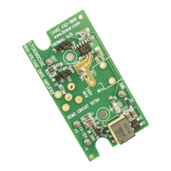
Demonstration circuit
1979A
amplifier featuring the
LTC
flyback converter provides ±62V power to the LTC6090
for evaluating large signal performance. A jumper sets
the gain of the ultrahigh-input impedance circuit to either
unity (1×) or 20×. In the 20× mode, a signal input of just
3V can provide nearly full-swing output. In the unity-gain
setting, the part operates as a precision buffer for high
voltage signals.
performance summary
SYMBOL
PARAMETER
V
Input Signal, Maximum Usable
IN
I
V
Leakage Current
IN
IN
V
Output Voltage Range
OUT
V
Input to Supply Converter
SUPPLY
I
Quiescent Supply Current
SUPPLY
UVLO
Undervoltage Lockout
operating principles
The LTC6090 op amp is set up in the standard noninvert-
ing voltage-gain configuration. GAIN jumper JP2 provides
a means of controlling the gain by adding or deleting a
gain resistor in the feedback path by choosing the 1× or
20× setting.
A small
LT
8300
flyback converter is used to provide about
®
±65V from a convenient low voltage supply in the 7V to
12V range. A blue LED is in series with the minus supply
to the LTC6090, so the op amp actually sees a resultant
supply of about 65V/–62V. The LED provides a pleasant
is a high voltage CMOS
6090. An onboard isolated
®
Specifications are at T
CONDITIONS
Gain = 20×, Onset of Output Clipping
Gain = 1×, V
V
= Within Usable Range
IN
Gain = 20×, Onset of Output Clipping
V
= 9V, No Loading of Op Amp Output
IN
DEMO MANUAL DC1979A
High Voltage CMOS Amplifier
SPECIAL FORM-FACTOR
The DC1979A includes a preassembled power converter
and amplifier circuit on a small printed circuit, so the user
only needs to furnish a 7V to 12V power source to oper-
ate the demo. The layout has provisions for optional BNC
connectors and mounting features to install the board in
a standard plastic enclosure if a permanent utility unit is
desired. Refer to the Appendix for mechanical details.
Design files for this circuit board are available at
http://www.linear.com/demo
L, LT, LTC, LTM, Linear Technology and the Linear logo are registered trademarks of Linear
Technology Corporation. All other trademarks are the property of their respective owners.
= 25°C
A
Limited
CM
level of illumination at the 2.6mA quiescent current of
the op amp.
To minimize signal loading, no input load resistor is in-
cluded. The op amp can be connected to the instrumentation
with a coaxial cable at J2, since a 50Ω output termination
is included. No far-end termination should be used, as the
op amp cannot deliver large signals across a 100Ω DC
load. In the event of an output overload, the LTC6090,
having built-in thermal shutdown, will automatically go
into a low power state to protect itself from damage. After
LTC6090
MIN
TYP
MAX
UNITS
±3.1
±60
3
±62
7
9
12
62
6.5
dc1979af
V
V
pA
V
V
mA
V
1
Advertisement
Table of Contents

Related Manuals for Linear Technology 1979A


Summary of Contents for Linear Technology 1979A
- Page 1 Design files for this circuit board are available at http://www.linear.com/demo L, LT, LTC, LTM, Linear Technology and the Linear logo are registered trademarks of Linear Technology Corporation. All other trademarks are the property of their respective owners. performance summary Specifications are at T = 25°C...
-
Page 2: Operating Principles
Quick start proceDure Demonstration circuit 1979A is easy to set up to evalu- 3. Connect a signal generator at the IN+ and GND turrets. ate the performance of the LTC6090. Refer to Figure 1 10kHz sine wave at 1V is a good starting point. - Page 3 DEMO MANUAL DC1979A appenDix One especially useful purpose for the DC1979A is to THE CONSTRUCTION provide precision measurements in higher voltage cir- The following sketches show the hole placement for the cuits. The usual 10MΩ presented by most instruments BNC connectors and an optional toggle switch. The toggle will often unacceptably load such circuits and give highly switch is for use with a 9V battery that can fit inside the erroneous results.
-
Page 4: Parts List
DEMO MANUAL DC1979A appenDix Figure 4 is an interior photo of the finished unit including operation. Standard adapters can be used to transform the switch and 9V battery. The translucent blue Hammond the output into a banana-plug pair that can directly attach 1593KTBU was selected so the LED would be visible during the unit to a DMM, as shown in Figure 5. -
Page 5: Schematic Diagram
Information furnished by Linear Technology Corporation is believed to be accurate and reliable. However, no responsibility is assumed for its use. Linear Technology Corporation makes no representa- tion that the interconnection of its circuits as described herein will not infringe on existing patent rights. - Page 6 Linear Technology Corporation (LTC) provides the enclosed product(s) under the following AS IS conditions: This demonstration board (DEMO BOARD) kit being sold or provided by Linear Technology is intended for use for ENGINEERING DEVELOPMENT OR EVALUATION PURPOSES ONLY and is not provided by LTC for commercial use. As such, the DEMO BOARD herein may not be complete in terms of required design-, marketing-, and/or manufacturing-related protective considerations, including but not limited to product safety measures typically found in finished commercial goods.
- Page 7 X-ON Electronics Largest Supplier of Electrical and Electronic Components Click to view similar products for category: Amplifier IC Development Tools Click to view products by manufacturer: Analog Devices Other Similar products are found below : EVAL-ADCMP566BCPZ EVAL-ADCMP606BKSZ AD8013AR-14-EBZ AD8033AKS-EBZ AD8044AR-EBZ AD8225-EVALZ ADA4859-3ACP-EBZ ADA4862-3YR-EBZ DEM-OPA-SO-2B AD744JR-EBZ AD8023AR-EBZ AD8030ARJ-EBZ AD8040ARU-EBZ AD8073JR-EBZ AD813AR-14-EBZ AD848JR-EBZ ADA4858-3ACP-EBZ ADA4922-1ACP-EBZ 551600075-001/NOPB DEM-OPA-SO- 2E THS7374EVM EVAL-ADCMP553BRMZ EVAL-ADCMP608BKSZ MIOP 42109 EVAL-ADCMP609BRMZ MAX9928EVKIT+...
Need help?
Do you have a question about the 1979A and is the answer not in the manual?
Questions and answers